Table of Contents
Advertisement
Available languages
Available languages
Quick Links
Advertisement
Chapters
Table of Contents

Related Manuals for Roca A5A104AC00


Summary of Contents for Roca A5A104AC00
- Page 1 SMART SHOWER A5A104AC00 ES / EN...
-
Page 3: Table Of Contents
❚ CONTENIDO DESCRIPCIÓN DE LOS DISPOSITIVOS PRINCIPALES LISTA DE COMPONENTES DIMENSIONES ESPECIFICACIONES TÉCNICAS CONSEJOS DE INSTALACIÓN DESCRIPCIÓN GENERAL DE LA CONEXIÓN AJUSTES DE FÁBRICA EJEMPLOS DE INSTALACIÓN GUÍA DE INSTALACIÓN PRIMERA CONFIGURACIÓN... -
Page 4: Descripción De Los Dispositivos Principales
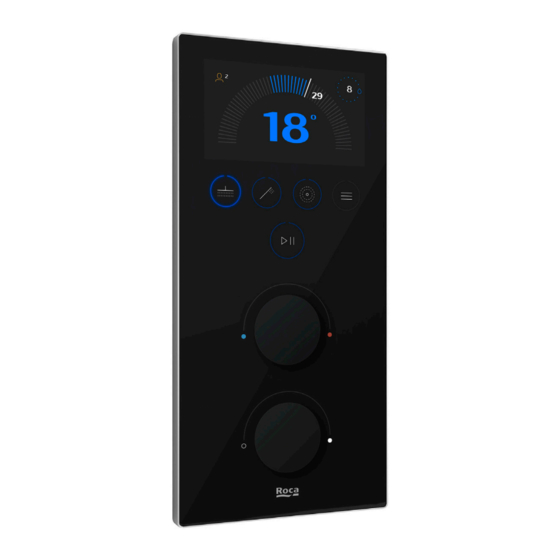
SMART SHOWER módulo WIFI/BT Panel diseñado para instalarse con el mezclador electrónico termostático Roca. Muestra los controles de temperatura y caudal, valores de temperatu ra (ºC), valores de caudal (l/min), temperatura de seguridad (38° C), progra mas, salida activa, alarmas y errores. Todos los parámetros preestablecidos en el panel se pueden personalizar. -
Page 5: Lista De Componentes
❚ LISTA DE COMPONENTES SMART SHOWER mezclador de 3 vías SMART SHOWER cable de alimentación 1m. A525454507 A525907507 SMART SHOWER panel SMART SHOWER módulo WIFI/BT A525454600 A525454707 SMART SHOWER caja empotrada SMART SHOWER cable panel 3m. Regleta de conexión A523887007 A525907607 Manual instalación SMART SHOWER fuente... -
Page 6: Dimensiones
❚ DIMENSIONES SMART SHOWER mezclador 3 vías SMART SHOWER módulo WIFI/BT Ø10,6 G 1/2” 70,5 SMART SHOWER fuente alimentación SMART SHOWER caja empotrada SMART SHOWER panel... -
Page 7: Especificaciones Técnicas
❚ ESPECIFICACIONES TÉCNICAS SMART SHOWER mezclador electrónico de 3 vías General Presión Máxima dinámica 6 bar (0,6 Mpa) ≤ 36W (máxima) Potencia máxima 1 W (en reposo) Mínima dinámica 1,5 bar (0,15 Mpa) Tensión nominal de ali 12 V DC (*) Dinámica recomendada 3 bar (0,3 Mpa) mentación Suministro diferencial... -
Page 8: Consejos De Instalación
❚ CONSEJOS DE INSTALACIÓN • En la pag 10 se muestran diferentes esquemas de instalación en función del número de salidas aplicadas. • Se recomienda instalar el mezclador, la fuente de alimentación, la conexión eléctrica y el módulo WIFI/BT del SMART SHOWER en el volumen 3 del entorno de ducha según el es quema en la página 11, de acuerdo a la normativa vigente (falso techo por ejemplo). -
Page 9: Descripción General De La Conexión
❚ DESCRIPCIÓN GENERAL DE LA CONEXIÓN OUT1 Siempre debe estar conectado G 1/2” Instalación G 3/4” fija Blanco Rojo Marrón Marrón Blanco Negro Azul Azul o negro LISTA DE COMPONENTES ACCESORIOS SUGERIDOS Mangueras hidráulicas G 1/2” de salida Mezclador Mangueras hidráulicas G 3/4” de alimentación Panel Cable de panel (3m) Cable fuente alimentación con... -
Page 10: Ejemplos De Instalación
❚ EJEMPLOS DE INSTALACIÓN 1 SALIDA 2 SALIDAS TAPAR TAPAR SALIDA 3 SALIDAS OUT 1 OUT 1 2 Y 3 OUT 2 1200 1200 3 SALIDAS OUT 1 OUT 2 Min. OUT 3 1200 1200... - Page 11 25A lDn 0.03A 10 ó 15A 2 x 1mm L Min. = 300 mm Según normativa vigente ØMin: 6 mm ØMax: 8,5 mm Obligatorio L max: Ubicación recomendada Incluidos Mezcladora, módulo WIFI/BT y fuente de alientación V = Volumen La mezcladora debe instalarse fuera de los volúmenes V0 y V1.
-
Page 12: Guía De Instalación
❚ GUÍA DE INSTALACIÓN 1200 Proceda con la instalación de tuberías de alimen Antes de instalar la mezcladora y los accesorios de tación y salidas a accesorios desde la mezcladora, salida, Proceda a purgar las tuberías, abriendo las así como manguera y conexiones eléctricas toman llaves de corte individual de las alimentaciones. - Page 13 TOP VIEW OUT 1 OUT 2 OUT 3 Min 115 CONN.3 COLD 12 Vdc Min 250 Min 50 Conecte el cable del panel Smart Shower Prepare la pared para la instalación de la caja empo A525907607 a la mezcladora en el conector mar trada del Panel Smart Shower y el tubo coarrugado cado como CONN.1.
- Page 14 TOP VIEW TOP VIEW Selle la pared alrededor de la caja empotrable con Conecte el cable de interfaz a la interfaz. Coloque el impermeable. panel A525454600 en la caja de montaje. TOP VIEW OUT 1 OUT 2 OUT 3 CONN 1 CONN 2 COLD POWER Presione la parte superior y sujete la parte inferior...
- Page 15 Encienda el suministro de voltaje y verifique que los botones azules de la interfaz estén iluminados en el modo STANDBY. Fuente de alimentación A525454807 Cable de 12V colores: Instalación fija Blanco Rojo Marrón Marrón Blanco Negro Azul Azul o negro IMPORTANTE: Conecte el cable de la fuente de alimentación a la fuente de alimentación A525454807.
-
Page 16: Primera Configuración
❚ PRIMERA CONFIGURACIÓN Elija el idioma deseado para la interfaz de usuario Selección de idioma English 中文 Español Elija uso privado (hogar y hasta 3 usuarios) o público (hoteles por ejemplo). Modo de ducha Privado Público A continuación, se muestran las siguientes pantallas de información: Puedes mejorar tu Recuerda realizar el experiencia de ducha... - Page 17 El sistema verifica las salidas para analizar el flujo y presión del agua. ACCEDER AL MENÚ PRINCIPAL REINICIAR ‘SISTEMA’ Usuarios Configuración Sistema Tocar para acceder al menú. Girar selector para resaltar ‘SISTEMA’ y tocar ELEGIR FUNCIÓN Start up Start up Limpieza El sistema verifica las salidas para analizar el flujo Desinfección...
- Page 18 ❚ CONTENTS MAIN DEVICES DESCRIPTION COMPONENT LIST DIMENSIONS TECHNICAL SPECIFICATIONS INSTALLATION TIPS CONNECTION OVERVIEW FACTORY SETTINGS INSTALLATION EXAMPLES INSTALLATION GUIDELINES FIRST CONFIGURATION...
-
Page 19: Main Devices Description
SMART SHOWER PANEL HOWER panel SMART SHOWER módulo WIFI/BT Panel designed to be installed with the Roca thermostatic electronic mixer. It shows the temperature and flow controls, temperature va lues (ºC), flow values (l / min), safety temperature (38 ° C), programs, active output, alarms and errors. -
Page 20: Component List
❚ COMPONENT LIST SMART SHOWER 3 way mixer SMART SHOWER power supply cable 1m. A525454507 A525907507 SMART SHOWER panel SMART SHOWER WIFI/BT module A525454600 A525454707 SMART SHOWER concealed box SMART SHOWER panel cable 3m. Strip connector A523887007 A525907607 Installation manual SMART SHOWER power Check-valve straight link &... -
Page 21: Dimensions
❚ DIMENSIONS SMART SHOWER 3 ways mixer SMART SHOWER WIFI/BT module Ø10,6 G 1/2” 70,5 SMART SHOWER power supply SMART SHOWER panel concealed box SMART SHOWER panel... -
Page 22: Technical Specifications
❚ TECHNICAL SPECIFICATIONS SMART SHOWER 3 WAY ELECTRONIC MIXER General Pressure ≤ 36W (max) Maximum dynamic 6 bar (0.6 Mpa) Maximum load ≤ 1 W (StandBy) Minimum dynamic 1,5 bar (0.15 Mpa) Recommended dyna Rated Impulse voltage 12 V DC (*) 3 bar (0.3 Mpa) Maximum differential IP Protection Rating... -
Page 23: Installation Tips
❚ INSTALLATION TIPS • On page 25 different installation schemes are shown depending on the number of outputs applied. • It is recommended to install the mixer, the power supply, the electrical connection and the WIFI/BT module of the SMART SHOWER in volume 3 of the shower environment according to the figure on page 26, according to current regulations (false ceiling for example). -
Page 24: Connection Overview
❚ CONNECTION OVERVIEW OUT1 Must be always connected G 1/2” Fixed G 3/4” installation White Brown Brown White Black Blue Blue or black LISTA DE COMPONENTES ACCESORIOS SUGERIDOS Hydraulic hoses G 1/2” outlet Mixer Hydraulic hoses G 3/4” intlet Panel Panel cable (3m) Power supply shielded cable with connector (1m) -
Page 25: Installation Examples
❚ INSTALLATION EXAMPLES 1 OUTLET 2 OUTLETS TAPS OUT 3 OUT 2 OUT 1 OUT 1 OUT 3 OUT 2 1200 1200 3 OUTLETS OUT 1 OUT 2 Min. OUT 3 1200 1200... - Page 26 25A lDn 0.03A 10 ó 15A 2 x 1mm L Min. = 300 mm According to current legislation ØMin: 6 mm ØMax: 8,5 mm Mandatory L max: Recommended location Included Mixer, WIFI/BT module and power supply V = Volume The mixer must be installed out of volumes V0 and V1. The power supply and electrical connection muste be installed out of volumes V0, V1 and V2.
-
Page 27: Installation Guidelines
❚ INSTALLATION GUIDELINES 1200 Proceed with the installation of supply pipes and Before installing the mixer and the outlet acces outlets to accessories from the mixer, as well as sories, proceed to purge the pipes, opening the in hose and electrical connections taking as reference dividual cutoff valves of the supplies. - Page 28 TOP VIEW OUT 1 OUT 2 OUT 3 Min 115 CONN.3 COLD 12 Vdc Min 250 Min 50 Connect the Smart Shower A525907607 panel ca Prepare the wall for the installation of the recessed ble to the mixer on the connector marked CONN.1. box of the Smart Shower Panel and the corrugated Connect the “WIFI/BT”...
- Page 29 TOP VIEW TOP VIEW Seal the wall around the recessed box with water Connect the interface cable to the interface. Place proof. panel A525454600 in the mounting box. TOP VIEW OUT 1 OUT 2 OUT 3 CONN 1 CONN 2 COLD POWER Press the top and secure the bottom with the...
-
Page 30: First Configuration
Turn on the voltage supply and verify that the blue buttons on the interface are lit in STANDBY mode. A525454807 power supply 12V cable colors: Fixed installation White Brown Brown White Black Blue Blue or black MPORTANT: Connect the power supply cable to the power supply A525454807. It is highly recommended to protect the power supply and Mixer against water placing them in a dry zone. - Page 31 Choose private use with 3 different users (home) or public with one user (hotels, etc). Shower mode Private Public Next, the following information screens show: Remember to run Improve your the Startup before shower experience starting to use your downloading the app shower Smart Shower The system verifies the outputs to analyze the flow and pressure of the water.
- Page 32 Roca Sanitario, S.A. Avda. Diagonal, 513 08029 Barcelona SPAIN www.roca.com...
Need help?
Do you have a question about the A5A104AC00 and is the answer not in the manual?
Questions and answers