Table of Contents

Subscribe to Our Youtube Channel
Related Manuals for Sigma BM40


Summary of Contents for Sigma BM40
- Page 1 Via Artigianato 85 – 25030 Torbole Casaglia. (BRESCIA) – ITALY – Tel 030 265 04 79 –Fax 030 265 01 43 USE AND MAINTENANCE INSTRUCTION MANUAL PLANETARY MIXER BM40 MECHANICAL SPEED VARIATION Instruction manual BMC-40 -VVM- 1 of 19...
-
Page 2: Table Of Contents
USE AND MAINTENANCE INSTRUCTION MANUAL MECHANICAL SPEED VARIATION PLANETARY MIXER BM40 This instruction, use and maintenance manual provides the instructions necessary for transportation, starting-up, use and maintenance of the mixer. It must be consulted before any one of these acts. -
Page 3: Safety Instructions
SAFETY INSTRUCTIONS. The safe and systematic use of the mixer is subordinated to compliance with behaviour and standards listed hereafter. Safety standards § Personnel must be in good physical and mental conditions and be adequately instructed on the use of the mixer having read this publication. The safety manager of the company, of the operating area and of the department, when choosing §... -
Page 4: Symbols Used And Qualifications Of The Personnel
Stability for machinery: if there is the possibility of slipping on wet or greasy surfaces or positioning the equipment in Obligation to disconnect unstable places (ships, planes or other), mixer before working on use the appropriate attachments for stable fixing (4 anchoring devices with 200 kg resistance, M8 screws) Obligation to carry out earthing. -
Page 5: Use And Description Of The Mixer
The symbols placed on a chapter mean to recall the specific skill needed for the intervention described therein. Wherever no symbols are present, the chapter applies to everyone. Symbol Description Features OPERATOR Person acquainted with operating, adjusting and programming the mixer and its protection and safety systems, who knows possible work cycles and ingredients to be used with relative maximum admitted amounts and who has read and understood the use and maintenance manual. -
Page 6: Instructions For Use
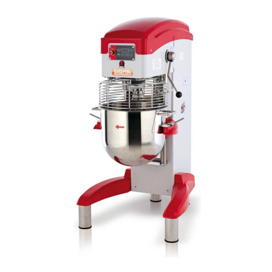
SPEED ELECTRICAL CHANGE PANEL LEVER BOWL LOCKING HANDLES GRID PROTECTION INSTRUCTIONS FOR USE To be able to work; the bowl must be mounted and the bowl protective grid closed. Otherwise it will be blocked by the safety systems. DO NOT REMOVE OR TAMPER WITH THE ELECTRICAL OR MECHANICAL GUARDS OR SAFETY DEVICES ON THE MACHINE. - Page 7 Best Mix control Panel BOWL STOP DIGITAL LIFT UP BUTTON DISPLAY Figure 1 BUTTON CICLO STOP EMERGENCY BUTTON SETTING BOWL SELECTIONS START BUTTON LIFT DOWN BUTTONS BUTTON BUTTON First of all be sure the Emergency stop button is released . The mixer can properly work as Manual or under the Digital timer.
- Page 8 WORKING WITH THE DIGITAL TIMER: If you would like to set the Timer, please press button “MODE” . You should see onto the digital lcd display, the last programmed time as “minutes:seconds” . (figure 3). In case you agree with the timing already set, just press “START” and the mixer will begin to work and the countdown will indicate the resting working time.
-
Page 9: Identification, Position Of The Operator And Dangerous Areas
The mixer is provided with a lever to change the tool rotation speed. This mixer has 7 different speeds. ATTENTION: ALWAYS change the speed while the mixer is moving to allow the variable pulley belt to position correctly. In order to remove the mixture, wait until the tool has stopped. Then turn the protection grid. Use the arrow ê... -
Page 10: Technical Data, Packaging, Dimensions And Weight
There is a plate on the back of the mixer like the one shown which carries indications concerning the manufacturer, the type of machine, serial number, electrical features, frequency, absorbed power and the number of phases and the year of construction. The figure at the side shows the position of the plate, that of the operator respect to the mixer and the AS danger area which must be free from people for a distance A = 250 mm. -
Page 11: Transportation And Handling
TRANSPORTATION AND HANDLING. Machine without pallet. Due to its instability , the mixer must be handled with a suitably-sturdy strap, having it pass below the head, as in the figure at the right. Before lifting, stand the grid up vertically §... -
Page 12: Installation
INSTALLATION The mixer must stand in a vertical position, on a smooth surface sufficiently sturdy for the load (floor with resistance over 20 km/cm2). If in danger of tipping over, anchor the mixer to the floor using 4 plugs or bolts with a traction resistance over kg 300 (M8). Connection to electrical mains The electrical connection must be carried out by a specialised electrician, according to the modalities and standards in force in the country where it is installed. -
Page 13: Cleaning And Maintenance Operations
CLEANING AND MAINTENANCE OPERATIONS. CONTROL OF INSTALLED SAFETY SYSTEMS AND ELECTRICAL SYSTEM The installed safety systems and the electrical system are subject to periodical checks carried out by a specialised electrician. Key of control intervals: Key of how to carry out the controls: (INTERVAL) (METHOD) d = daily. -
Page 14: Extraordinary Maintenance
To carry out interventions not specially mentioned in the manual, refer proof. Do not wash it with to personnel authorised by SIGMA SrL. To replace the motor or the running water. Clean it with a circuit boards, or else if the mixer falls, contact our assistance service... -
Page 15: Periodical Maintenance
Mixer screws A2 [Nm] Installed safety systems check. § SPARE PARTS: SIGMA SrL reserves the right to carry out all the modifications that it deems necessary for its mixer models. It is therefore always necessary to specify: Type of mixer •... -
Page 16: Spare Parts List
SPARE PARTS LIST * *: this is a brand new generation of Sigma planetary mixers, the following chart can be little bit different from the machine you have. In case contact the factory to get the updated one. We will soon provide you the real line diagrams of it. - Page 17 SPARE PARTS LIST TABLE: Position Quantity Code Description 095016-A Driven pulley BM-40 101022-5 Planetary shaft BM-60 101023-2 Driving bevel gear Z22 BMX-60 version with reduction gear 097201 Silkscreen printing BM-20 Timer START/STOP button ON/OFF switch 194021-1 Long grid wheel pin 194022-1 Grid guide wheel 194023-1...
-
Page 18: Blockage Of Machinery And Necessary Remedies
BLOCKAGE OF MACHINERY AND NECESSARY REMEDIES OPERATION POSSIBLE CAUSES REPAIR ANOMALIES Turning the master switch into 1) Plug not inserted correctly or wires 1) Check connection position, the warning light does detached not turn on Pressing the START button, the 1) The slide is not in position or the 1) Lift the slide and reposition it mixer does not start... - Page 19 Obligations of informing users Information model for users of “professional” products INFORMATION FOR USERS In compliance with art. 13 of the Legislative Decree of July 25, 2005, n. 151 “Implementing of Directives 2002/95/EC, 2002/96/EC and 2003/108/EC, relative to the reduction of the use of hazardous substances in electrical and electronic appliances as well as disposal of waste”...
Need help?
Do you have a question about the BM40 and is the answer not in the manual?
Questions and answers