Table of Contents
Advertisement
Quick Links
Model S4000C
Intelligent Sensor for
Combustible Gas Detection
The information and technical data disclosed in
this document may be used and disseminated
only for the purposes and to the extent
specifically authorized in writing by General
Monitors.
Instruction Manual
0307
General Monitors reserves the right to change
published specifications and designs without
prior notice.
MANS4000C
Part No.
MANS4000C
Revision
G/03-07
Advertisement
Table of Contents

Related Manuals for General Monitors S4000C


Summary of Contents for General Monitors S4000C
- Page 1 General Monitors. Instruction Manual 0307 General Monitors reserves the right to change published specifications and designs without prior notice. MANS4000C Part No. MANS4000C...
- Page 2 S4000C This page intentionally left blank...
-
Page 3: Table Of Contents
Maintaining the X/P Integrity ....................12 4.0 OPERATION......................... 13 Start-Up Checklist ........................13 Start-Up ............................13 Relay Reset..........................13 User Selectable Options ......................14 4.4.1 Model S4000C User Menu Structure ................15 4.4.2 Calibration Level ......................15 4.4.3 Warning Relay Settings ....................16 4.4.4 Alarm Relay Settings....................16 4.4.5 MODBUS Channel 1 Settings..................17... - Page 4 MODBUS Write Response Message ................27 Function Codes Supported ......................27 Exception Responses and Exception Codes ................27 8.6.1 Exception Response ....................27 8.6.2 Exception Code......................28 S4000C Command Register Locations..................29 S4000C Command Register Details ..................30 8.8.1 Analog .........................30 8.8.2 Mode ...........................30 8.8.3 Status/Error .........................30 8.8.4 Unit Type........................31...
- Page 5 Approvals ..........................39 Sensitivities to Other Gases.....................39 Spare Parts and Accessories....................41 9.6.1 Sensors ........................41 9.6.2 Sensor Housing......................41 9.6.3 Sensor Accessories ....................41 9.6.4 Calibration Equipment....................41 9.6.5 Intelligent Transmitter (S4000C) Replacement Parts ..........42 9.6.6 Recommended Spare Parts for One (1) Year ............42 FMRC Approval........................43...
-
Page 6: Table Of Figures
Figure 2: Spring Type Terminal Block Operation ....................2 Figure 3: Screw Type Terminal Block Operation....................2 Figure 4: Model S4000C Intelligent Sensor......................3 Figure 5: Outline and Mounting Dimensions ......................6 Figure 6: Spring Type Terminal Block Operation ....................8 Figure 7: Screw Type Terminal Block Operation.................... - Page 7 S4000C Table of Tables Table 1: TB2 Power and Signal Connections......................7 Table 2: Ground or Common Connections......................9 Table 3: Power Connections ..........................9 Table 4: Analog Signal Connections ........................10 Table 5: Alarm Relay Connections ........................10 Table 6: Warn Relay Connections........................10 Table 7: Fault Relay Connections ........................
-
Page 8: Quick Start Guide
3. Adjustable wrench for conduit or cable gland connections (not included). It is not necessary to seal the Model S4000C housing to maintain its explosion-proof integrity; however, conduit runs containing wires attached to the Model S4000C’s relay contacts must be sealed. -
Page 9: Figure 2: Spring Type Terminal Block Operation
NOTE: Power must remain disconnected until all other wiring connections have been made. The maximum distance between the Model S4000C and the power supply is 3430 feet or 1040 meters (each cable run should be as short as possible). See Section 9.3.3 for cable length specifications. - Page 10 S4000C Worldwide service is available by calling: Lake Forest, California Toll Free: +1-800-446-4872 (24 hr. service) Phone: +1-949-581-4464 Fax: +1-949-581-1151 Phone: +1-281-855-6000 Houston, Texas Fax: +1-281-855-3290 Ireland Phone: +353-91-751175 Fax: +353-91-751317 Singapore Phone: +65-6748-3488 Fax: +65-6748-1911 United Arab Emirates Phone: +971-4-8815751...
-
Page 11: Mounting And Wiring
This manual provides instruction for installing and operating General Monitors’ Model S4000C for Combustible Gas Detection. While the S4000C is easy to install and operate, this manual should be read in full and the information contained herein understood before attempting to place the system in service. - Page 12 S4000C Periodic Testing of Field Devices Periodic testing/calibrating should be performed per the manufacturer’s recommendations and instructions. Testing/Calibrating procedures should include, but not be limited to: • Verify integrity of all optical surfaces and devices • For flame detectors, use the appropriate test lamp When testing produces results outside of the manufacturer’s specifications, replacement of the...
-
Page 13: Product Description
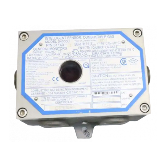
S4000C 2.0 Product Description 2.1 General Description The Model S4000C is an intelligent sensor for the detection of combustible gases and vapors. The microprocessor-based electronics processes information at the sensor site, within an explosion-proof housing. A digital display provides indications and display codes that can be viewed through a window in the cover. -
Page 14: Installation
• The transmitter should not be placed where contaminating substances may coat it. • Although the Model S4000C is RFI resistant, it should not be mounted in close proximity to radio transmitters or similar equipment. • Locate the Model S4000C where prevailing air currents contain the maximum concentration of gas. -
Page 15: Remote Mounting Of The Sensor From The Electronics
The presence of poisons and contaminants in an area does not necessarily preclude the use of a Model S4000C Intelligent Sensor. The feasibility of using a sensor in such areas must be determined by an analysis of the specific factors in each application and General Monitors should be consulted before attempting any such installation. -
Page 16: Figure 5: Outline And Mounting Dimensions
S4000C The overall and mounting dimensions for the Model S4000C (Figure 5) should be used when making installation determinations. A complete list of the mechanical specifications can be found in Section 9.3.2. To prevent possible corrosion due to moisture or condensation, it is recommended that the conduit connected to the Model S4000C housing be sealed, or contain a drain loop. -
Page 17: Terminal Connections
14 AWG to 20 AWG and the Screw Type terminal block accepts 12 AWG to 18 AWG stranded or solid wire. Each wire should be stripped before wiring the Model S4000C Intelligent Sensor. To connect wiring to the Spring Type terminal block, insert a screwdriver into the orange tab and press down (Figure 6), opening the terminal. -
Page 18: Dc Power And Ground Connections
NOTE: Up to 12 AWG wire can be used if it is carefully stripped (on a Screw Type terminal) (Figure 6). 3.5.3 DC Power and Ground Connections The customer must provide primary DC power unless one of the following General Monitors Modules is being used with the Model S4000C: • DC130 Dual-Channel Readout/Relay Display Module... -
Page 19: Analog Signal Connections
Table 3: Power Connections 3.5.4 Analog Signal Connections The Model S4000C Intelligent Sensor provides a 4 to 20mA output signal. It can be sent up to 9000 feet (2740 meters) to a General Monitors’ readout/relay display module, or an industrial analog to digital converter, or a computer-based monitor, a PLC, a DCS, etc. -
Page 20: Terminal Block Tb3 - Relay Connections
Pin 8 or 9 Analog In Table 4: Analog Signal Connections If a device other than a General Monitors’ readout/relay display module is being used, the DC ground, COM, of both systems must be connected together. 3.5.5 Terminal Block TB3 – Relay Connections TB3 contains the connections for the Relay Contacts (optional). -
Page 21: European Union (Eu) Approved Applications
S4000C Figure 9: Relay Protection for DC and AC Loads European Union (EU) Approved Applications: The ALARM relay contact ratings are 8A, 30 V RMS/42.4 V peak or 8A @ 30 VDC resistive max. North American Approved Applications: The ALARM relay contact ratings are 8A @ 250 VAC and 8A @ 30 VDC resistive max. -
Page 22: Maintaining The X/P Integrity
Anytime the cover of the Model S4000C housing is removed, or the cover bolts are loosened, the flame path between the lid and the housing is affected. If power is to be left on while removing the cover or loosening the cover bolts on the Model S4000C, it will be necessary to declassify the area. -
Page 23: Operation
4. Verify that the signal wiring is correct. 5. Verify that the power supply is connected properly. The Model S4000C is powered by +24VDC (20 to 36 VDC voltage range). The detector will output a low voltage (F6) fault at 18.5 VDC or below. -
Page 24: User Selectable Options
4.4 User Selectable Options The Model S4000C Intelligent Sensor includes many selectable options to provide the user with the most flexible combustible gas detector possible. These options include Adjustable Calibration Level, Warn and Alarm Relay Set Points and Configuration, and MODBUS Communications Settings. -
Page 25: Model S4000C User Menu Structure
4mA. 4.4.2 Calibration Level To adjust the calibration level of the Model S4000C, apply the magnet to the GM Logo on the cover of the unit, until “SE” is displayed, then remove the magnet. This puts the unit into Setup Mode. -
Page 26: Warning Relay Settings
4.4.4 Alarm Relay Settings To adjust the Alarm Relay Settings of the Model S4000C, apply the magnet to the GM Logo on the cover of the unit until “SE” is displayed, then remove the magnet. This puts the unit into Setup Mode. -
Page 27: Modbus Channel 1 Settings
4.4.5 MODBUS Channel 1 Settings To change the MODBUS Channel 1 settings of the Model S4000C, apply the magnet to the GM Logo on the cover of the unit until “SE” is displayed, then remove the magnet. This puts the unit into Setup Mode. -
Page 28: Gas Check Mode
4.5 Gas Check Mode The sensor response can be checked without activating external alarms by placing the Model S4000C in Gas Check Mode. In this Mode, the alarm relays are inhibited and the analog output is fixed at 1.5mA. 4.5.1 Procedure for Checking the Calibration Place the magnet over the GM Logo on the cover of the Model S4000C. -
Page 29: Calibration Procedure
Entering Calibration Mode automatically disables the alarm circuits by sending a 1.5mA output signal and disabling the Warn and Alarm relays, if present. This will also prevent activation of the remote relay contacts when using a General Monitors Readout/Relay Display Module with the Model S4000C. -
Page 30: Aborting Calibration
NOTE: Once gas has been applied, it is not possible to abort a calibration. If the Model S4000C is placed in the Calibration Mode and no gas is applied for six minutes, the unit will revert to a Fault condition. Re-applying the magnet over the GM Logo will return the unit to operational mode with the previous calibration values unchanged. -
Page 31: Calibration Equipment
Pre-mixed calibration gases at approximately 50% LEL are available, in lecture bottles, at 1200 psi, 8.3 MPa maximum pressure. Hydrogen Methane Propane Please specify the gas upon ordering. Spare bottles containing these gases may be ordered. Methane and Hydrogen lecture bottles may be returned to General Monitors for refilling. -
Page 32: Maintenance
The neoprene rubber gasket, if it is found dry should also be lubricated with Type P80 lubricant, available from General Monitors (P/N 610-010). 5.2 Storage The Model S4000C Combustible Gas Detector should be stored in a clean, dry area, and within the temperature and humidity ranges quoted in the Appendix under Environmental Specifications. -
Page 33: Troubleshooting
Fault is detected, the output signal will drop to 0mA, the Fault relay will de-energize and a Fault code will be displayed. The output signal will inform a remote display module that the Model S4000C is in the Fault Mode. The display will indicate a Fault code that can be viewed at the sensor site. -
Page 34: F6 Low Supply Voltage
6.1.8 F9 Gas Check Period Exceeded If the Model S4000C is left in the gas check mode for more than six minutes without a Test Gas being applied or if test gas is left on the gas check mode for more than 6 minutes, this fault will occur. -
Page 35: Customer Support
S4000C 7.0 Customer Support 7.1 General Monitors’ Offices Area Phone/Fax/Email UNITED STATES Toll Free: +1-800-446-4872 Corporate Office: Phone: +1-949-581-4464 26776 Simpatica Circle Fax: +1-949-581-1151 Lake Forest, CA 92630 Email: info@generalmonitors.com 9776 Whithorn Drive Phone: +1-281-855-6000 Houston, TX 77095 Fax: +1-281-855-3290 Email: gmhou@generalmonitors.com... -
Page 36: Modbus Interface
S4000C ID (Address) Function Code Read Holding Registers Byte Count No. of Data Bytes Data Hi 00-FF (Hex) S4000C Hi Byte Status Data Data Lo 00-FF (Hex) S4000C Lo Byte Status Data CRC Lo 00-FF (Hex) CRC Lo Byte CRC Hi... -
Page 37: Modbus Write Command Protocol (Query/Response)
An abnormal communications query produces one of four possible events: 1. If the S4000C does not receive the query due to a communications error, then no response is returned from the S4000C and the master device will eventually process a timeout condition for the query. -
Page 38: Exception Code
8.6.2 Exception Code Exception Code Field: In a normal response, the S4000C returns data and status in the data field, which was requested in the query from the master. In an exception response, the S4000C returns an exception code in the data field, which describes the S4000C condition that caused the exception. -
Page 39: S4000C Command Register Locations
S4000C 8.7 S4000C Command Register Locations Master Register Parameter Function Type Scale Access Address Address Analog 0-20mA Current Output Value 16-Bit 0000 40001 Mode Indicates and Controls Mode 0001 40002 Status/Error Indicates Errors 0002 40003 Not Used 40004 Unit Type... -
Page 40: S4000C Command Register Details
16-bit value. The scaling is 0 - 65535 decimal which corresponds to 0 - 21.7mA. 8.8.2 Mode A read returns the present mode of the S4000C. A write command changes the mode to the requested mode. Exception: Returns an Exception Code 01 (illegal function) if an illegal write is requested. -
Page 41: Unit Type
8.8.7 Alarm Settings A read returns the present Alarm settings of the S4000C. A write command changes the settings to the requested values. The set points are programmable in 5% FS steps. NOTE: The maximum alarm setting for the S4000C is 60%. -
Page 42: Warn Settings
(7-0) 8.8.8 Warn Settings A read returns the present Warn settings of the S4000C. A write command changes the settings to the requested values. The set points are programmable in 5% FS steps. NOTE: The maximum warn setting for the S4000C is 60%. -
Page 43: Com1 Baud Rate
S4000C 8.8.10 Com1 Baud Rate A read command returns the current baud rate for Com1. A write command changes the baud rate to the requested values. Valid settings are shown in the table below. Factory default is 19,200. Baud Rate... -
Page 44: Com2 Data Format
A write to this register with a data value of 1 will reset any latched alarms provided the current gas level is below the alarm set point. On the S4000C it will also reset the latching over-range function provided the gas level is below 100% LEL. -
Page 45: Function Code Errors
S4000C 8.8.21 Function Code Errors A read indicates the number of Function Code Errors that occurred in the slave device. The maximum count is 255 and then the counter will rollover to zero and begin counting again. 8.8.22 Starting Address Errors The counter is incremented for each address that does not equal the device address. -
Page 46: Appendix
9.0 Appendix 9.1 Warranty General Monitors warrants the Model S4000C to be free from defects in workmanship or material under normal use and service within two years from the date of shipment. General Monitors will repair or replace without charge any such equipment found to be defective during the warranty period. -
Page 47: Specifications
S4000C 9.3 Specifications 9.3.1 System Specifications Sensor Type: Continuous diffusion, low temperature catalytic bead Sensor Life: 3 to 5 years typical +3% LEL up to 50% LEL Accuracy: +5% LEL > 51% LEL Zero Drift: Less than 5% of full scale per year Response Time: T50<10 sec. -
Page 48: Environmental Specifications
S4000C Cable Requirements: 3-wire shielded cable. Max. distance between S4000C and power source @ 24VDC nominal (20 ohm loop): FEET METERS 3430 1040 1900 1500 1000 Table 17: 24VDC Cable Lengths Max. distance for analog output (650 ohms max): FEET... -
Page 49: Approvals
S4000C 9.4 Approvals CSA, FM, ATEX approved. Complies with ANSI/ISA-12.13.01-2000 performance requirements 9.5 Sensitivities to Other Gases The S4000C responds to the following list of hydrocarbons up to C10 Injection volumes Cal Ratio Gases %LEL M.W. Density 50%lel/3L 50%lel/5L Methane... -
Page 50: Table 20: Chemical List From1994 Nfpa
S4000C Ethyl Acetate 88.1 119 ul 199 ul Ethyl Amine 45.1 140 ul 234 ul Ethyl Benzene 106.2 60 ul 100 ul Ethyl Ether 72.2 120 ul 200 ul Gasoline 100.2 107 ul 179 ul Heptane 100.2 94 ul 157 ul Hexane 86.2... -
Page 51: Spare Parts And Accessories
S4000C 9.6 Spare Parts and Accessories To order spare parts and/or accessories, please contact your nearest General Monitors representative, or General Monitors directly, and give the following information: • Part Number of Spare Part or Accessory • Description of Spare Part or Accessory •... -
Page 52: Intelligent Transmitter (S4000C) Replacement Parts
922-009 Pressure Regulator Gauge 1400152-1 Small Calibration Cup 1400154 Large Calibration Cup 925-026 Tubing 9.6.5 Intelligent Transmitter (S4000C) Replacement Parts 31146-1 Control Board Electronics 31151-1 Output Board Electronics 31156-1 Display Board Electronics 31170-1 Enclosure Cover Assembly with Window... -
Page 53: Fmrc Approval
FMRC Approval Standards for Combustible Gas Detectors, Class Numbers 6310 & 6320. FMRC has tested the Model S4000C using the specifications listed in Section 9.2. This permits an operating temperature of -40°F to +167°F (-40°C to +75°C), a general purpose sensor (10001-1 or 10058-1) attached to the housing (i.e. - Page 54 ADDENDUM Product Disposal Considerations This product may contain hazardous and/or toxic substances. EU Member states shall dispose according to WEEE regulations. For further General Monitors’ product WEEE disposal information please visit: www.generalmonitors.com/customer_support/faq_general.html All other countries or states: please dispose of in accordance with existing federal, state and local...
Need help?
Do you have a question about the S4000C and is the answer not in the manual?
Questions and answers