Table of Contents
Advertisement
Quick Links
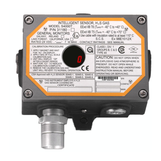
Model S4000T
Intelligent Sensor for
Hydrogen Sulfide Gas Detection
The information and technical data disclosed in
this document may be used and disseminated
only for the purposes and to the extent
specifically authorized in writing by General
Monitors.
Instruction Manual
03-03
General Monitors reserves the right to change
published specifications and designs without
prior notice.
MANS4000T
Part No.
MANS4000T
Revision
F/03-03
Advertisement
Table of Contents

Related Manuals for General Monitors S4000T


Summary of Contents for General Monitors S4000T
- Page 1 General Monitors. Instruction Manual 03-03 General Monitors reserves the right to change published specifications and designs without prior notice. MANS4000T Part No. MANS4000T...
-
Page 2: Warning
NOTE - The Model S4000T Intelligent Sensor is easy to install; however, this manual should be read and understood before attempting to operate the sensor. -
Page 3: System Integrity Verification
Model S4000T System Integrity Verification General Monitors’ mission is to benefit society by providing solutions through industry-leading safety products, services and systems that save lives and protect capital resources from the dangers of hazardous flames, gases and vapors. The safety products you have purchased should be handled carefully and installed, calibrated and maintained in accordance with the respective product instruction manual. - Page 4 Model S4000T documented procedure, including a calibration log, maintained by plant personnel or third party testing services. Periodic System Verification The following system verifications should be performed at least annually: Verify wiring, terminal connections and stability of mounting for all integral safety equipment including, but not limited to: •...
-
Page 5: Quick Start Guide
• The transmitter should not be placed where it may be coated by contaminating substances. • Although the Model S4000T is RFI resistant, it should not be mounted in close proximity to radio transmitters or similar equipment. • Locate the Model S4000T where prevailing air currents contain the maximum concentration of gas. -
Page 6: Remote Mounting Of The Sensor From The Electronics
Section 9.2.2. To prevent possible corrosion due to moisture or condensation, it is recommended that the conduit connected to the Model S4000T housing be sealed or contain a drain loop. Each conduit run from a hazardous location to a non-hazardous location should be sealed so that gases, vapors, and/or flames cannot pass beyond the seal. - Page 7 Quick Start Guide vapors, or flames from one electrical installation to another, through the conduit system. It is not necessary to seal the Model S4000T housing to maintain its explosion-proof integrity; however, conduit runs containing wires attached to the Model S4000T’s relay contacts must be sealed (see Section 3.5).
-
Page 8: Terminal Connections
It is recommended that a shielded cable be used for making power and output signal connections on the Model S4000T. The terminal block accepts 14 AWG to 20 AWG stranded or solid wire. Each wire should be stripped before wiring the Model S4000T Intelligent Sensor. -
Page 9: Dc Power And Ground Connections
• DT220 Dual-Channel Display Module • TA202A Trip Amplifier Module without a PS002 Since the Model S4000T is designed to operate continuously, a power switch is not included, in order to prevent accidental system shutdown. NOTE - Power must remain disconnected until all other wiring connections have been made. -
Page 10: Analog Signal Connections
Figure 6 Power Connections 1.3.4 Analog Signal Connections A 4 to 20mA output signal is provided by the Model S4000T Intelligent Transmitter. This signal can be sent up to 9000 feet (2740 meters) using 14 AWG wire to: • A General Monitors readout/relay display module, or •... -
Page 11: Terminal Block Tb3 - Relay Connections
Model S4000T Quick Start Guide 1.3.5 Terminal Block TB3 – Relay Connections TB3 contains the connections for the Relay Contacts (optional). The function for the Warn and Alarm Relay connections vary, according to the normal state of the relay. Use the following as a guide for determining the Normally Open (NO) and the... -
Page 12: European Union (Eu) Approved Applications
Model S4000T Quick Start Guide North American Approved Applications - The ALARM relay contact ratings are 8A @ 250 VAC and 8A @ 30 VDC resistive max. European Union (EU) Approved Applications - The ALARM relay contact ratings are 8A, 30 V RMS/42.4 V peak or 8A @ 30 VDC resistive max. - Page 13 Model S4000T Quick Start Guide NOTE - The instrument is now ready to operate! Please consult the manual for more information on the instrument’s many features. NOTE - If you have any problems in the set-up or testing of the detector, please refer to the “Trouble Shooting Section”, or call the factory direct.
-
Page 14: Table Of Contents
Model S4000T Table of Contents Warning ................... i System Integrity Verification .................. ii Quick Start Guide ................. iv Product Location.................iv 1.1.1 Sensor Poisons and Contaminants ........iv 1.1.2 Remote mounting of the Sensor from the Electronics... v Mounting and Wiring ................v 1.2.1... - Page 15 ................15 Start-Up Checklist................15 Start-Up ................15 Relay Reset ................15 User Selectable Options..............16 4.4.1 Model S4000T User Menu Structure........17 4.4.2 Sensor Range..............17 4.4.3 Warning Relay Settings............18 4.4.4 Alarm Relay Settings............18 4.4.5 Modbus Channel 1 Settings ..........19 4.4.6...
- Page 16 Function Codes Supported............... 30 Exception Responses and Exception Codes ........31 8.6.1 Exception Response ............31 8.6.2 Exception Code ..............31 S4000T Command Register Locations ..........33 S4000T Command Register Details..........34 8.8.1 Analog ................34 8.8.2 Mode ................34 8.8.3...
- Page 17 Spare Parts and Accessories ............43 9.4.1 Sensors ................44 9.4.2 Sensor Housing ..............44 9.4.3 Sensor Accessories............. 44 9.4.4 Calibration Equipment ............44 9.4.5 Intelligent Sensor (S4000T) Replacement Parts....45 9.4.6 Recommended Spare Parts for One (1) Year..... 45 FMRC Approval 45...
- Page 18 Model S4000T Table of Figures Figure 1 S4000T Outline and Mounting Dimensions........vi Figure 2 Power and Signal Connections ............vii Figure 3 Terminal Block Operation..............viii Figure 4 Wire Strip Length................viii Figure 5 Ground or Common Connections............ix Figure 6 Power Connections ................ix Figure 7 Analog Signal Connections ...............
-
Page 19: Introduction
Model S4000T 2.0 Introduction General Description The Model S4000T is an Intelligent Sensor for the detection of Hydrogen Sulfide S) gas. The microprocessor-based electronics process information at the sensor site, within an explosion-proof housing. A digital display provides indications and display codes that can be viewed through a window in the cover. - Page 20 Model S4000T This page left intentionally blank...
-
Page 21: Installation
WARNING - Installation and Maintenance must be carried out by suitably skilled and competent personnel only. WARNING - The Model S4000T Intelligent Sensor contains components which can be damaged by static electricity. Special care must be taken when wiring the system to ensure that only the connection points are touched. -
Page 22: Choosing Product Locations
• The transmitter should not be placed where it may be coated by contaminating substances. • Although the Model S4000T is RFI resistant, it should not be mounted in close proximity to radio transmitters or similar equipment. • Locate the Model S4000T where prevailing air currents contain the maximum concentration of gas. -
Page 23: Remote Mounting Of The Sensor From The Electronics
Model S4000T 3.3.1 Remote mounting of the Sensor from the Electronics If it is necessary to remotely mount the sensor from the electronics and the housing, the maximum distance can be no greater than 3700 feet (1125) meters, using 14 AWG wire. -
Page 24: Mounting And Wiring
Section 9.2.2. To prevent possible corrosion due to moisture or condensation, it is recommended that the conduit connected to the Model S4000T housing be sealed, or contain a drain loop. Each conduit run from a hazardous location to a non-hazardous location should be sealed so that gases, vapors, and/or flames can not pass beyond the seal. - Page 25 Model S4000T NOTE - The system’s full two-year warranty will be voided if customer personnel or third parties damage the system during repair attempts. Sensor heads exposed to the elements may require the accessory mounting threads to be lubricated. Grease must not be used. As an alternate, PTFE (teflon) tape may be used on sensor accessory threads.
-
Page 26: Terminal Connections
Model S4000T Terminal Connections The terminal blocks (TB) are located inside of the housing and can by accessed by removing the cover. A label on the inside of the housing cover provides details of all the terminal connections. 3.5.1 Terminal Block TB1 – Sensor Connections TB1 contains the four sensor connections, white (W), black (B), red (R) and green (G). -
Page 27: Dc Power And Ground Connections
• DT220 Dual-Channel Display Module • TA202A Trip Amplifier Module without a PS002 Since the Model S4000T is designed to operate continuously, a power switch is not included, in order to prevent accidental system shutdown. NOTE - Power must remain disconnected until all other wiring connections have... -
Page 28: Analog Signal Connections
Figure 18 Power Connections 3.5.4 Analog Signal Connections A 4 to 20mA output signal is provided by the Model S4000T Intelligent Transmitter. This signal can be sent up to 9000 feet (2740 meters) to: • A General Monitors readout/relay display module, or •... -
Page 29: Terminal Block Tb3 - Relay Connections
Pin 8 or 9 Analog In Figure 19 Analog Signal Connections If a device other than a General Monitors readout/relay display module is being used, the DC ground, COM, of both systems must be connected together. 3.5.5 Terminal Block TB3 – Relay Connections TB3 contains the connections for the Relay Contacts (optional). -
Page 30: European Union (Eu) Approved Applications
Model S4000T Figure 23 Relay Protection for DC and AC Loads North American Approved Applications - The ALARM relay contact ratings are 8A @ 250 VAC and 8A @ 30 VDC resistive max. European Union (EU) Approved Applications - The ALARM relay contact ratings are 8A, 30 V RMS/42.4 V peak or 8A @ 30 VDC resistive max. -
Page 31: Maintaining The X/P Integrity
CSA Standard C22.2 No.30-M1986, FM 3615 and EN50014. Anytime the cover of the Model S4000T housing is removed or the cover bolts are loosened, the flame path between the lid and the housing is effected. If power is to be left on while removing the cover or loosening the cover bolts on the Model S4000T, it will be necessary to declassify the area. - Page 32 Model S4000T This page left intentionally blank...
-
Page 33: Operation
4. Verify that the signal wiring is correct. 5. Verify that the power supply is connected properly. The Model S4000T is powered by +24VDC (20 to 36 VDC voltage range). The detector will output a low voltage fault (F6) at 18.5 VDC or below. -
Page 34: User Selectable Options
Warn relays are active. Latching relays can only be reset if the gas concentration has fallen below the respective relay setpoint. User Selectable Options The Model S4000T Intelligent Sensor includes many selectable options to provide the user with the most flexible H S gas detector possible. These options include Selectable Sensor Range, Warn and Alarm Relay Setpoints and Configuration, and Modbus Communications Settings. -
Page 35: Model S4000T User Menu Structure
To adjust the Sensor Range of the Model S4000T, apply the magnet to the GM Logo on the cover of the unit until “SE” is displayed, then remove the magnet. This puts the unit into Setup Mode. After a few seconds “Sr”... -
Page 36: Warning Relay Settings
See Section 4.6.1. 4.4.3 Warning Relay Settings To adjust the Warning Relay Settings of the Model S4000T, apply the magnet to the GM Logo on the cover of the unit until “SE” is displayed, then remove the magnet. This puts the unit into Setup Mode. After a few seconds “Lo” will be displayed. Apply and remove the magnet to change the Warning or “Low”... -
Page 37: Modbus Channel 1 Settings
4.4.5 Modbus Channel 1 Settings To adjust the Modbus Channel 1 settings of the Model S4000T, apply the magnet to the GM Logo on the cover of the unit until “SE” is displayed, then remove the magnet. This puts the unit into Setup Mode. After a few seconds “CH1” will be displayed. -
Page 38: Gas Check Mode
1.5mA. 4.5.1 Procedure for Checking the Calibration: Place the magnet over the GM Logo on the cover of the Model S4000T. Remove the magnet when a flashing pair of bars, “- -” (Figure 26), appear on the display (about ten seconds). -
Page 39: Calibration
Entering Calibration Mode automatically disables the alarm circuits by sending a 1.5mA output signal and disabling the Warn and Alarm relays, if present. This will also prevent activation of the remote relay contacts when using a General Monitors Readout/Relay Display Module with the Model S4000T. -
Page 40: Aborting Calibration
NOTE - Once gas has been applied, it is not possible to abort a calibration. If the Model S4000T is placed in the Calibration Mode, and no gas is applied for twelve minutes, the unit will revert to a Fault (F2) condition. Re-applying the magnet over the GM Logo will return the unit to operational mode with the previous calibration values unchanged. -
Page 41: Calibration Equipment
5% of full-scale. See Section 9.4 for available equipment. 4.7.2 H S Portable Purge Calibrator An alternate method for introducing calibration or test gas to the Model S4000T is available. The H S Portable Purge Calibrator is a compact, practical, accurate and safe system for field calibration of H S Sensors. -
Page 42: Maintenance
Health & Safety Executive component approval No. 1051U for use as a jointing compound on flameproof electrical enclosures. This is available from General Monitors. The neoprene rubber gasket should also be lubricated with Type P80 lubricant available from General Monitors (P/N 610-010). Storage The Model S4000T H... -
Page 43: Troubleshooting
This fault indicates that one of the sensor circuit leads is open-circuited. ACTION - Check the integrity of all sensor connections, and ensure that the cable from the Model S4000T to the remote sensor is not damaged. If this does not correct the problem, replace the sensor and recalibrate. -
Page 44: F7 - Eeprom Verification Failure
6.1.8 F9 - Gas Check Period Exceeded If the Model S4000T is left in the gas check mode for more than twelve minutes with Test Gas applied, this fault will occur. ACTION - Place the magnet over the GM Logo on the cover to return the unit to normal operation. -
Page 45: Customer Support
Model S4000T 7.0 Customer Support General Monitors’ Offices Area Phone/Fax/Email UNITED STATES Corporate Office: 26776 Simpatica Circle Phone: +1-949-581-4464 Lake Forest, CA 92630 Fax: +1-949-581-1151 Email: sales@generalmonitors.com 9776 Whithorn Drive Phone: +1-281-855-6000 Houston, TX 77095 Fax: +1-281-855-3290 Email: gmhou@generalmonitors.com UNITED KINGDOM... - Page 46 Model S4000T This page left intentionally blank...
-
Page 47: Modbus Interface
Referenced to S4000T Slave Address 1-247* (Decimal) S4000T ID (Address) Function Code Read Holding Registers Starting Address Hi** Not Used by S4000T Starting Address Lo** 00-FF (Hex) S4000T Commands No. Of Registers Hi Not Used by S4000T No. Of Registers Lo No. -
Page 48: Modbus Read Response Message
S4000T ID (Address) Function Code Read Holding Registers Byte Count No. Of Data Bytes Data Hi 00-FF (Hex) S4000T Hi Byte Status Data Data Lo 00-FF (Hex) S4000T Lo Byte Status Data CRC Lo 00-FF (Hex) CRC Lo Byte CRC Hi... -
Page 49: Exception Responses And Exception Codes
An abnormal communications produces one of four possible events: 1) If the S4000T does not receive the query due to a communications error, then no response is returned from the S4000T and the master device will eventually process a timeout condition for the query. - Page 50 An unrecoverable error occurred while the S4000T was attempting to perform the requested action. Acknowledge The S4000T has accepted the request and is processing it, but a long duration of time will be required to do so. This response is returned to prevent a timeout error from occurring in the master.
-
Page 51: S4000T Command Register Locations
Model S4000T S4000T Command Register Locations Master Register Parameter Function Type Scale Access Address Address Analog 0-20mA Current Output Value 16-Bit 0000 40001 Mode Indicates and Controls Mode 0001 40002 Status/Error Indicates Errors 0002 40003 Not Used 40004 Unit Type... -
Page 52: S4000T Command Register Details
16-bit value. The scaling is 0 - 65535 decimal which corresponds to 0 - 21.7mA. 8.8.2 Mode A read returns the present mode of the S4000T. A write command changes the mode to the requested mode. Exception: Returns an Exception Code 01 (illegal function) if an illegal write is requested. -
Page 53: Status/Error
8.8.7 Alarm Settings A read returns the present Alarm settings of the S4000T. A write command changes the settings to the requested values. The setpoints are programmable in 5% FS steps. (1% FS steps for 20ppm range). -
Page 54: Warn Settings
Setpoint (7-0) 8.8.8 Warn Settings A read returns the present Warn settings of the S4000T. A write command changes the settings to the requested values. The setpoints are programmable in 5% FS steps. (1% FS steps for 20ppm range). A 1 in the 9 bit position means the output is latching, a 0 means it is Non-Latching. -
Page 55: Com1 Baud Rate
Model S4000T 8.8.10 Com1 Baud Rate A read command returns the current baud rate for Com1. A write command changes the baud rate to the requested values. Valid settings are shown in the table below. Factory default is 19,200. Baud Rate... -
Page 56: Com2 Data Format
Model S4000T 8.8.14 Com2 Data Format A read command returns the current data format for Com2. Write command changes the data format to the requested values. Valid settings are shown in the table below. Factory default is 8-N-1. Data Parity... -
Page 57: Starting Address Errors
Model S4000T 8.8.21 Starting Address Errors The counter is incremented for each address that does not equal the device address. A read indicates the number of Starting Address Errors that occurred in the slave device. The maximum count is 255 and then the counter will rollover to zero and begin counting again. - Page 58 Model S4000T This page left intentionally blank...
-
Page 59: Appendix
Model S4000T 9.0 Appendix Principle of Operation General Monitors uses a proprietary Metal Oxide Semiconductor (MOS) film on the sensor for detecting Hydrogen Sulfide (H S) gas. The MOS film is deposited onto a substrate between two electrodes. With no gas present, the measured resistance between these two electrodes is very high (in the mega-ohms). -
Page 60: Mechanical Specifications
Faults Monitored: Open AO, calibration error, sensor heater error, low DC supply, EEPROM, EPROM, setup error, gas check time exceeded, switch error. Cable Requirements: 3-wire shielded cable. Max. distance between S4000T and power source @ 24 VDC nominal FEET METERS... -
Page 61: Environmental Specifications
• FM, CE and ATEX Marking pending. Spare Parts and Accessories To order spare parts and/or accessories, please contact your nearest General Monitors Representative or, General Monitors directly, and give the following information: • Part Number of Spare Part or Accessory •... -
Page 62: Sensors
Model S4000T 9.4.1 Sensors 50445-1 0 to 100ppm, Aluminum Body, Wire Screen Arrestor 50445-5 0 to 50ppm, Aluminum Body, Wire Screen Arrestor 50445-9 0 to 20ppm, Aluminum Body, Wire Screen Arrestor 50448-1 0 to 100ppm, Stainless Steel Body, Wire Screen Arrestor... -
Page 63: Intelligent Sensor (S4000T) Replacement Parts
FMRC approved. The following sensors have been FMRC approved for use with the Model S4000T: • 50445-1 Aluminum Body H S Gas Specific MOS Sensor, 0 to 100 ppm •...
Need help?
Do you have a question about the S4000T and is the answer not in the manual?
Questions and answers