Sign In
Upload
Manuals
Brands
General Monitors Manuals
Accessories
S4000C
General Monitors S4000C Manuals
Manuals and User Guides for General Monitors S4000C. We have
1
General Monitors S4000C manual available for free PDF download: Instruction Manual
General Monitors S4000C Instruction Manual (54 pages)
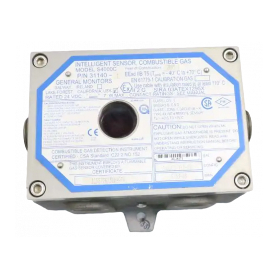
Intelligent Sensor for Combustible Gas Detection
Brand:
General Monitors
| Category:
Accessories
| Size: 0 MB
Table of Contents
Table of Contents
3
Table of Figures
6
Quick Start Guide
8
Tools Required
8
Figure 1: Outline and Mounting Dimensions
8
Figure 2: Spring Type Terminal Block Operation
9
Figure 3: Screw Type Terminal Block Operation
9
Mounting and Wiring
11
Terminal Connections
11
1 Introduction
11
Protection for Life
11
Special Warnings
11
System Integrity Verification
11
2 Product Description
13
General Description
13
Figure 4: Model S4000C Intelligent Sensor
13
3 Installation
14
Receipt of Equipment
14
Tools Required
14
Choosing Product Locations
14
Remote Mounting of the Sensor from the Electronics
15
Mounting and Wiring
15
Figure 5: Outline and Mounting Dimensions
16
Terminal Connections
17
Terminal Block TB1 - Sensor Connections
17
Terminal Block TB2 - Power and Signal Connections
17
Table 1: TB2 Power and Signal Connections
17
DC Power and Ground Connections
18
Figure 6: Spring Type Terminal Block Operation
18
Figure 7: Screw Type Terminal Block Operation
18
Figure 8: Wire Strip Length
18
Analog Signal Connections
19
Table 2: Ground or Common Connections
19
Table 3: Power Connections
19
Terminal Block TB3 - Relay Connections
20
Table 4: Analog Signal Connections
20
Table 5: Alarm Relay Connections
20
Table 6: Warn Relay Connections
20
Table 7: Fault Relay Connections
20
European Union (EU) Approved Applications
21
Cable Termination in the Non-Hazardous Area
21
Figure 9: Relay Protection for DC and AC Loads
21
Maintaining the X/P Integrity
22
4 Operation
23
Start-Up Checklist
23
Start-Up
23
Relay Reset
23
User Selectable Options
24
Figure 10: Relay Reset
24
Calibration Level
25
Figure 11: User Menu Structure
25
Model S4000C User Menu Structure
25
Alarm Relay Settings
26
Warning Relay Settings
26
MODBUS Channel 1 Settings
27
MODBUS Channel 2 Settings
27
Gas Check Mode
28
Procedure for Checking the Calibration
28
Calibration
28
Figure 12: Calibration Check
28
Calibration Procedure
29
Figure 13: Automatic Calibration Mode
29
Figure 14: Calibration in Progress Mode
29
Figure 15: Calibration Complete Mode
29
Aborting Calibration
30
Adjustable Calibration Level
30
Initializing the Remaining Sensor Life
30
Remaining Sensor Life
30
Calibration Equipment
31
Portable Purge Calibrator
31
5 Maintenance
32
General Maintenance
32
Storage
32
6 Troubleshooting
33
Fault Codes & Their Remedies
33
F2 Failed to Complete Calibration
33
F3 EEPROM Checksum Error
33
F4 Sensor Error
33
F5 Unused
33
F6 Low Supply Voltage
34
F7 EEPROM Verification Failure
34
F8 Failure to Complete Setup
34
F9 Gas Check Period Exceeded
34
F10 Switch Error
34
7 Customer Support
35
General Monitors' Offices
35
Table 8: GM Locations
35
8 Modbus Interface
36
Baud Rate
36
Data Format
36
MODBUS Read Status Protocol (Query/Response)
36
MODBUS Read Query Message
36
MODBUS Read Response Message
36
Table 9: Data Format
36
MODBUS Write Command Protocol (Query/Response)
37
MODBUS Write Query Message
37
MODBUS Write Response Message
37
Function Codes Supported
37
Exception Responses and Exception Codes
37
Exception Response
37
Exception Code
38
Table 10: Exception Codes
38
S4000C Command Register Locations
39
Table 11: Command Register Locations
39
S4000C Command Register Details
40
Analog
40
Mode
40
Status/Error
40
Table 12: Command Register Locations Cont
40
Unit Type
41
Software Revision
41
Status Block
41
Alarm Settings
41
Warn Settings
42
Com1 Address
42
Com1 Baud Rate
43
Com1 Data Format
43
Com2 Address
43
Com2 Baud Rate
43
Table 13: Com1 Baud Rate
43
Table 14: Com1 Data Format
43
Table 15: Com2 Baud Rate
43
Com2 Data Format
44
Cal Level
44
Reset Alarms
44
Sensor Life
44
Hazardwatch (Co - Calibration Output)
44
Total Receive Errors
44
Bus Activity Rate
44
Table 16: Com2 Data Format
44
Function Code Errors
45
Starting Address Errors
45
Number of Register Errors
45
RXD CRC Hi Errors
45
RXD CRC Low Errors
45
Clear Comm Errors
45
9 Appendix
46
Warranty
46
Principle of Operation
46
Specifications
47
System Specifications
47
Mechanical Specifications
47
Electrical Specifications
47
Environmental Specifications
48
Table 17: 24VDC Cable Lengths
48
Table 18: Analog Output Cable Lengths
48
Table 19: Sensor Cable Lengths
48
Approvals
49
Sensitivities to Other Gases
49
Table 20: Chemical List From1994 NFPA
50
Spare Parts and Accessories
51
Sensors
51
Sensor Housing
51
Sensor Accessories
51
Calibration Equipment
51
Intelligent Transmitter (S4000C) Replacement Parts
52
Recommended Spare Parts for One (1) Year
52
FMRC Approval
53
Advertisement
Advertisement
Related Products
General Monitors S4000CH
General Monitors S4000T
General Monitors S214
General Monitors S216A
General Monitors S104
General Monitors S5000
General Monitors S800
General Monitors Categories
Security Sensors
Accessories
Control Unit
Monitor
Measuring Instruments
More General Monitors Manuals
Login
Sign In
OR
Sign in with Facebook
Sign in with Google
Upload manual
Upload from disk
Upload from URL