Table of Contents
Advertisement
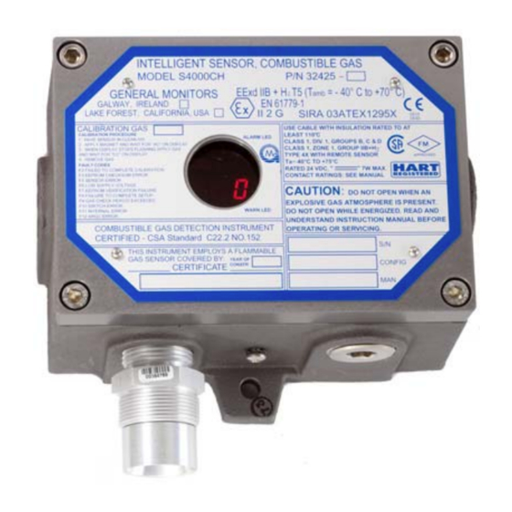
Model S4000CH
Intelligent Sensor for
Combustible Gas Detection
The information and technical data disclosed in
this document may be used and disseminated
only for the purposes and to the extent
specifically authorized in writing by General
Monitors.
Instruction Manual
General Monitors reserves the right to change
published specifications and designs without
prior notice.
Part No.
Revision
10-16
MANS4000CH
MANS4000CH
N/10-16
Advertisement
Table of Contents

Subscribe to Our Youtube Channel
Related Manuals for General Monitors S4000CH


Summary of Contents for General Monitors S4000CH
- Page 1 General Monitors. Instruction Manual 10-16 General Monitors reserves the right to change published specifications and designs without prior notice. MANS4000CH Part No. MANS4000CH...
- Page 2 Model S4000CH This page intentionally left blank...
-
Page 3: Table Of Contents
3.10 User Selectable Options ......................22 3.11 Available Separate Purchase Options ..................22 3.11.1 Model S4000CH User Menu Structure ............... 23 3.11.2 Calibration Level ......................24 3.11.3 Warning Relay Settings ....................24 3.11.4 Alarm Relay Settings....................24 3.11.5 Modbus Channel 1 Settings ..................25 3.11.6 Modbus Channel 2 Settings .................. - Page 4 Function Codes Supported ...................... 38 Exception Responses and Exception Codes ................38 6.6.1 Exception Response ....................38 6.6.2 Exception Code ......................39 S4000CH Command Register Locations ................. 40 S4000CH Command Register Details ..................42 6.8.1 Analog (00h) ........................ 42 6.8.2 Mode (01h) ........................42 6.8.3...
- Page 5 Model S4000CH 6.8.7 Analog Value (06h) ..................... 43 6.8.8 Mode & Error (07h) ..................... 44 6.8.9 Error & Sensor Life (08h) .................... 44 6.8.10 Display (0x09h & 0x0Ah) .................... 44 6.8.11 Serial Number (0Bh/0Ch) .................... 45 6.8.12 Alarm Settings (0Dh) ....................45 6.8.13 Warn Settings (0Eh) ....................
- Page 6 Spare Parts and Accessories ....................63 7.6.1 Sensors ........................63 7.6.2 Sensor Housing ......................63 7.6.3 Sensor Accessories ....................63 7.6.4 Calibration Equipment ....................63 7.6.5 S4000CH Replacement Parts ..................64 7.6.6 Recommended Spare Parts for One (1) Year ............64 FM Approval ..........................65...
-
Page 7: Table Of Figures
Figure 6: Screw Type Terminal Block Operation ....................3 Figure 7: Model S4000CH Intelligent Sensor ......................8 Figure 8: Model S4000CH Intelligent Sensor with ARGC ..................9 Figure 9: ARGC Remote Junction Box Assembly (P/N 80155-1) ................9 Figure 10: Outline and Mounting Dimensions in inches ..................12 Figure 11: Outline and Mounting Dimensions (ARGC) in inches ................. - Page 8 Model S4000CH Table of Tables Table 1: TB2 Power and Signal Connections ....................... 15 Table 2: Ground or Common Connections ......................17 Table 3: Power Connections ..........................17 Table 4: Analog Signal Connections ........................18 Table 5: Alarm Relay Connections ........................18 Table 6: Warn Relay Connections ........................
-
Page 9: Quick Start Guide
Model S4000CH Quick Start Guide Mounting and Wiring Tools Required “5mm” Allen head wrench to remove enclosure lid (included with gas detector). Flat-head screwdriver maximum 3/16” (5 mm) width for terminal block connections (included with gas detector). Adjustable wrench for conduit or cable gland connections (not included). -
Page 10: Figure 3: Sensor Remote Installation In Inches
Model S4000CH Figure 3: Sensor Remote Installation in inches Figure 4: ARGC Remote Installation... -
Page 11: Terminal Connections
It is recommended that a minimum three-wire shielded cable be used for making the power and 0-20mA Output connection on TB2 of the S4000CH. It is also recommended that separate two-wire shielded twisted pair cables be used for making the Modbus connections. The spring type terminal block accepts 14 AWG to 20 AWG and the screw type terminal block accepts 12 AWG to 18 AWG stranded or solid wire. - Page 12 NOTE: Power must remain disconnected until all other wiring connections have been made. The maximum distance between the S4000CH and the power supply is 3430 feet or 1040 meters (each cable run should be as short as possible). See Section 7.3.4 for cable length specifications.
-
Page 13: Introduction
This manual provides instruction for installing and operating General Monitors’ Model S4000CH for combustible gas detection. While the S4000CH is easy to install and operate, this manual should be read in full and the information contained herein understood before attempting to place the system in service. -
Page 14: System Integrity Verification
Model S4000CH construction; therefore, they shall only be used with the enclosure type and where the surface temperature, at the point of mounting, is as detailed below: Cement Ambient Range Enclosure Type 2850FT Cat 11, -40°C to +70°C Enclosures that are certified by a notified body and... - Page 15 Model S4000CH Periodic Testing of Field Devices Periodic testing/calibrating should be performed per the manufacturer’s recommendations and instructions. Testing/calibrating procedures should include, but not be limited to: Verify integrity of all optical surfaces and devices When testing produces results outside of the manufacturer’s specifications, replacement of the suspect device(s) should be performed as necessary.
-
Page 16: Product Description
Model S4000CH 2.0 Product Description 2.1 General Description The Model S4000CH is an intelligent sensor for the detection of combustible gases and vapors. The microprocessor-based electronics process information at the sensor site within an explosion-proof housing. A digital display provides indications and display codes that can be viewed through a window in the cover. -
Page 17: Figure 8: Model S4000Ch Intelligent Sensor With Argc
Model S4000CH Figure 8: Model S4000CH Intelligent Sensor with ARGC NOTE: The image in Figure 8 is for reference only. See section 7.3 for actual product specifications. Figure 9: ARGC Remote Junction Box Assembly (P/N 80155-1) -
Page 18: Installation
The sensor should not be placed where contaminating substances may coat it. Although the S4000CH is RFI resistant, it should not be mounted in close proximity to radio transmitters or similar equipment. Locate the S4000CH where prevailing air currents contain the maximum concentration of gas. -
Page 19: Remote Mounting Of The Sensor From The Electronics
The presence of poisons and contaminants in an area does not necessarily preclude the use of a Model S4000CH intelligent sensor. The feasibility of using a sensor in such areas must be determined by an analysis of the specific factors in each application and General Monitors should be consulted before attempting any such installation. -
Page 20: Mounting And Wiring
WARNING: Conduits must be sealed within 18 inches of the enclosure. The outline and mounting dimensions for the S4000CH (Figure 10) should be used when making installation determinations. A complete list of the mechanical specifications can be found in Section 7.3.2. -
Page 21: Terminal Connections
General Monitors recommends that a calibration schedule be established and followed. NOTE: The S4000CH full two-year warranty will be voided if customer personnel or third parties damage the S4000CH during repair attempts. Sensor heads exposed to the elements may require the accessory mounting threads to be lubricated. -
Page 22: Figure 12: S4000Ch Terminal Block Locations
Model S4000CH Figure 12: S4000CH Terminal Block Locations Figure 13: Remote Junction Box Terminal Block... -
Page 23: Terminal Block Tb1 - Sensor Connections
12 AWG to 18 AWG stranded or solid wire. Each wire should be stripped before wiring the S4000CH. To connect wiring to the spring type terminal block, insert a screwdriver into the orange tab and press down (Figure14), opening the terminal. -
Page 24: Figure 15: Screw Type Terminal Block Operation
Model S4000CH To connect wiring to the screw type terminal block, (Figure 15) use a screwdriver to loosen the top screw counter clockwise. Insert the wire into the terminal and tighten the top screw clock wise. Check the hold of the wire by GENTLY tugging it to ensure it is locked in. -
Page 25: Dc Power And Com Connections
Table 3: Power Connections 3.5.4 Analog Signal Connections The S4000CH Intelligent Sensor provides a 4 to 20 mA output signal. It can be sent up to 9000 feet (2740 meters) to a General Monitors readout/relay display module, or an industrial analog to digital converter, or a computer-based monitor, a PLC, a DCS, etc. -
Page 26: Argc Terminal Connections
Output 4-20 mA Table 4: Analog Signal Connections If a device other than a General Monitors readout/relay display module is being used, the DC ground, COM, of both systems must be connected together. 3.5.5 ARGC Terminal Connections The solenoid valve is not polarized. Either wire can go to either terminal. One wire goes to the Calibrate Input/ARGC Output and the other wire goes to the +24 volts. -
Page 27: European Union (Eu) Approved Applications
Model S4000CH TB3 position Relay Contact (Energized) Normally Open Common Normally Closed Table 7: Fault Relay Connections NOTE: Fault relay is normally energized. Relay will change state after power up. WARNING: Contact with PCB components should be avoided to prevent damage by static electricity. -
Page 28: Maintaining The X/P Integrity
CSA Standard C22.2 No.30, FM 3615, and EN/IEC 60079-1. Anytime the cover of the S4000CH housing is removed, or the cover bolts are loosened, the flame path between the lid and the housing is affected. If power is to be left on while removing the cover or loosening the cover bolts on the S4000CH, it will be necessary to declassify the area. -
Page 29: Start-Up Checklist
Verify that the signal wiring is correct. Verify that the power supply is connected properly. The S4000CH is powered by +24 VDC (20 to 36 VDC voltage range). The detector will output a low voltage (F6) fault at 18.5 VDC or below. -
Page 30: User Selectable Options
3.10 User Selectable Options The S4000CH includes many selectable options to provide the user with the most flexible combustible gas detector possible. These options include Adjustable Calibration Level, Warn and Alarm Relay Set Points and Configuration, and Modbus Communications Settings. -
Page 31: Model S4000Ch User Menu Structure
Model S4000CH 3.11.1 Model S4000CH User Menu Structure FAULT User Menu Structure Operate “rSt” “AC” “SE” “ - - ” Time OUT “SE” “SE” Enter Set Calibration “Fi” Enter Gas Check “cL” Level 25 % - 90 % Calibration Mode... -
Page 32: Calibration Level
NOTE: Refer to Section 3.14.1 for the calibration procedure. To adjust the calibration level of the S4000CH, apply the magnet to the GM logo on the cover of the unit, until “SE” is displayed, then remove the magnet. This puts the unit into Setup Mode. -
Page 33: Modbus Channel 1 Settings
60% LEL. 3.11.5 Modbus Channel 1 Settings To change the Modbus Channel 1 settings of the S4000CH, apply the magnet to the GM logo on the cover of the unit until “SE” is displayed, then remove the magnet. This puts the unit into Setup Mode. -
Page 34: Hart/Modbus Select
Default settings for Channel 2 are: address 2, 19.2k baud, 8-N-1. 3.12 HART/Modbus SELECT This option is not shown if HART was not purchased for the S4000CH. When HART is selected via setup, the Channel 2 setup is not displayed or available. When Channel 2 is changed from HART to Modbus, the previous settings are used. -
Page 35: Calibration
There are three methods for calibrating the S4000CH: Manually, with an RGC, or with an ARGC. NOTE: If the RGC or ARGC is not installed, the S4000CH calibration is identical to the S4000C. NOTE: If the Catalytic bead sensor is fitted with a splash guard, calibration must be performed with the splash guard in place. -
Page 36: Aborting Calibration
Model S4000CH seconds, while the unit acquires the zero reading. Ensure that the sensor is seeing clean air during this time. Calibration mode can also be entered via remote switch. This option cannot be used when the ARGC is enabled. -
Page 37: Adjustable Calibration Level
Model S4000CH If the S4000CH is placed in the Calibration Mode and no gas is applied for six minutes, the unit will revert to a Fault condition. Re-applying the magnet over the GM logo will return the unit to operational mode with the previous calibration values unchanged. -
Page 38: Remote Gas Calibrator
Figure 24: Remote Gas Calibrator (RGC, P/N 80153-1) 3.17 ARGC Gas Control The S4000CH has a Modbus or HART controlled output that can be used to turn the cal gas on and off remotely if the proper plumbing is provided. -
Page 39: Automatic Remote Gas Calibrator (Argc)
Model S4000CH 3.18 Automatic Remote Gas Calibrator (ARGC) The S4000CH has an optional Automatic Remote Gas Calibrator. The ARGC is a combination of the above P/N’s for local remote calibration (Figure 8). The ARGC can be remotely installed using the above P/N’s and P/N 32547-1 (Remote Junction Box, Figure 9). -
Page 40: Figure 26: Calibration Complete Mode
Model S4000CH If the initial reading is greater than 5% LEL, an ARGC error will be indicated. This means the valve could be leaking. The display will change to “AC” and the gas will be turned on. If the gas reading is less than 60% of the calibration gas, an ARGC error will be indicated. -
Page 41: Maintenance
General Monitors (P/N 610-010). 4.2 Storage The S4000CH Intelligent Sensor should be stored in a clean, dry area, and within the temperature and humidity ranges quoted in the Appendix under Environmental Specifications. Insert red dust caps into any vacant cable entry holes. -
Page 42: Troubleshooting
0 mA, the fault relay will de-energize and a fault code will be displayed. The output signal will inform a remote display module that the S4000CH is in the Fault Mode. The display will indicate a fault code that can be viewed at the sensor site. -
Page 43: F5 Unused
5.1.8 F9 Gas Check Period Exceeded If the S4000CH is left in the Gas Check Mode for more than six minutes or if test gas is left on the gas check mode for more than 6 minutes, this fault will occur. -
Page 44: F11 Internal Error
You can then apply the magnet over the display to clear the F12 error. 5.2 General Monitors’ Offices Area... -
Page 45: Modbus Interface
S4000CH ID (Address) Function Code Read Holding Registers Byte Count No. of Data Bytes Data Hi 00-FF (Hex) S4000CH Hi Byte Status Data Data Lo 00-FF (Hex) S4000CH Lo Byte Status Data CRC Lo 00-FF (Hex) CRC Lo Byte CRC Hi... -
Page 46: Modbus Write Command Protocol (Query/Response)
An abnormal communications query produces one of four possible events: If the S4000CH does not receive the query due to a communications error, then no response is returned from the S4000CH and the master device will eventually process a timeout condition for the query. -
Page 47: Exception Code
6.6.2 Exception Code Exception Code Field: In a normal response, the S4000CH returns data and status in the data field, which was requested in the query from the master. In an exception response, the S4000CH returns an exception code in the data field, which describes the S4000CH condition that caused the exception. -
Page 48: S4000Ch Command Register Locations
Model S4000CH 6.7 S4000CH Command Register Locations Master Register Parameter Function Type Scale Access Address Address Analog 0-20mA Current Output Value 16-Bit 0000 40001 Mode Indicates and Controls Mode 0001 40002 Status/Error Indicates Errors 0002 40003 Not Used 0003 40004... - Page 49 Model S4000CH Master Register Parameter Function Type Scale Access Address Address HART EN/DE Enable/Disable 001D 40030 Transmit a constant 1 or 0 HART Test Value 0,1,2 001E 40031 signal Ch1Total Total # of Receive Errors Value 8-Bit 0020 40033 Receive Errors...
-
Page 50: S4000Ch Command Register Details
16-bit value. The scaling is 0 - 65535 decimal which corresponds to 0 - 21.7 mA. 6.8.2 Mode (01h) A read returns the present mode of the S4000CH. A write command changes the mode to the requested mode. A data value of 08 will start calibration mode if the unit is in the run mode. -
Page 51: Status/Error (03H)
A read returns the decimal value 4004. This identifies the S4000CH. 6.8.5 Software Revision (05h) A read returns the software revision of the S4000CH in 2 ASCII characters. 6.8.6 Status Block (06h) A read returns a 6-byte message containing the Analog (2 bytes), Mode (1 byte), Status/Error (2 bytes), and Sensor Life (1 byte) in that order. -
Page 52: Mode & Error (07H)
Model S4000CH 6.8.8 Mode & Error (07h) See Mode (02) Calibration Complete 8000 Spanning 4000 Zero Complete, Waiting for Gas 2000 Zeroing 1000 Calibration Mode 0800 Calibration Check Mode 0400 Run Mode 0200 Startup Mode 0100 Alarm 0080 Warn 0040... -
Page 53: Serial Number (0Bh/0Ch)
If an alarm exists a write is not allowed and a device exception code is returned. A read returns the present Alarm settings of the S4000CH. A write command changes the settings to the requested values. The set points are programmable in 5% FS steps. -
Page 54: Com1 Address (0Fh)
Model S4000CH Exception: Returns an Exception Code 01 (Illegal Function) if an illegal write is requested. Byte Function Bit Position Access High Not Used 15 MSB Read Not Used Read Not Used Read Not Used Read Not Used Read Not Used... -
Page 55: Com2 Address (12H)
COM 2 is user selectable to HART or Modbus if the unit is ordered with HART. HART or Modbus is selectable via Modbus or the display. For additional information on HART, see the S4000CH HART manual. When HART is selected there are changes to comply with the HART requirements. Since HART does not allow low current the actual current does not go below 3.5 mA. -
Page 56: Com2 Data Format (14H)
A write to this register with a data value of 1 will reset any latched alarms provided the current gas level is below the alarm set point. On the S4000CH it will also reset the latching over-range function provided the gas level is below 100% LEL. -
Page 57: Hazardwatch (Co - Calibration Output) (19H)
Model S4000CH 6.8.23 HazardWatch (Co – Calibration Output) (19h) HazardWatch indicates when a successful calibration takes place. In HazardWatch mode the current goes to 3.2 mA for 5 seconds then to 4.0 mA. An aborted calibration would go straight to 4.0 mA. A read to this register will return the status of the HazardWatch option. -
Page 58: Abort Calibration (1Fh)
Model S4000CH Code Results Normal Constant ones Constant zeros 6.8.28 Abort Calibration (1Fh) Sending a “1” will abort calibration. 6.8.29 Total Receive Errors (20h) A read indicates the total Modbus Comm. Hardware Receive Errors that occurred in the slave device. The maximum count is 65535 and then the counter will rollover to zero and begin counting again. -
Page 59: Overrun Errors (28H)
Model S4000CH 6.8.37 Overrun errors (28h) A read indicates the number of hardware UART Overrun Errors that occurred in the slave device. The maximum count is 65535 and then the counter will rollover to zero and begin counting again. 6.8.38 Framing Errors (29h) A read indicates the number of hardware UART Framing Errors that occurred in the slave device. - Page 60 If the unit fails Zero or Cal the event is not recorded. If the calibration is aborted the event is also not recorded. Note the Zero and Calibration are one operation in the S4000CH. There are a total of 10 event time stamps stored.
- Page 61 Model S4000CH Address Parameter Function Data Type Data range Access (hex) Structure time Hi byte – day, low Numeric value 0 – 65535 Warn byte – hour warning event log entries Structure time Hi byte – min, low Numeric value 0 –...
- Page 62 Model S4000CH Address Parameter Function Data Type Data range Access (hex) Structure time Hi byte – day, low Numeric value 0 – 65535 Fault byte – hour alarm event log entries Structure time Hi byte – min, low Numeric value 0 –...
-
Page 63: User Information (60H To 6Fh)
Model S4000CH Address Parameter Function Data Type Data range Access (hex) Structure time Hi byte – min, low Numeric value 0 – 65535 Calibrate byte – sec for event log entries Calibrate code Numeric value Calibrate Reserved Reserved Numeric value... -
Page 64: Rxd Crc Errors Hi (75H)
Model S4000CH 6.8.49 RXD CRC Errors Hi (75h) A read indicates the number of RXD CRC Errors that occurred in the slave device. The maximum count is 65535 and then the counter will rollover to zero and begin counting again. -
Page 65: Appendix
7.0 Appendix 7.1 Warranty General Monitors warrants the Model S4000CH to be free from defects in workmanship or material under normal use and service within two years from the date of shipment. General Monitors will repair or replace without charge any such equipment found to be defective during the warranty period. -
Page 66: Specifications
175 mA including sensor, all relays on 30 volts: 228 mA including sensor, all relays on 20 volts: .035 mA in addition to S4000CH current Current ARGC only: .85 Watts This is additional power required by the ARGC Power ARGC only: 8 A @ 250 VAC/8 A @ 30 VDC resistive max. -
Page 67: Cable Requirements
ARGC, and internal problem. Complies with EN 50270, EN 61000-6-4 EMC Protection: 7.3.4 Cable Requirements Cable Requirements: (w/out ARGC & with relays) 3-wire shielded cable. Max. Distance between S4000CH and power source @ 24 VDC nominal. Ohms/1K FEET METERS 1.588... -
Page 68: Remote Sensor Cable Lengths
Model S4000CH Table 18: ARGC Cable Lengths * Screw terminals only Max. distance for analog output (650 Ohms max): FEET METERS 9000 2740 5200 1585 3800 1160 2400 Table 19: Analog Output Cable Lengths NOTE: The analog circuit can tolerate a negative output up to -5 volts. -
Page 69: Approvals
Approved by the HART Communication Foundation. Compatible with Emersion 375 Field Communicator. Listed in Emerson Process Management’s Aware device list 7.5 Sensitivities to Other Gases The S4000CH responds to the following list of hydrocarbons up to C10. Injection volumes Cal Ratio Gases %LEL M.W. -
Page 70: Table 21: Chemical List
Model S4000CH Butyraldehyde 72.1 102 µl 171 µl Cyclohexane 84.2 86 µl 143 µl Diethyl Ketone (3-Pentanone) 86.1 103 µl 173 µl p-Dioxane 88.1 104 µl 174 µl Ethyl Acetate 88.1 119 µl 199 µl Ethyl Amine 45.1 140 µl 234 µl... -
Page 71: Spare Parts And Accessories
Model S4000CH 7.6 Spare Parts and Accessories To order spare parts and/or accessories, please contact the nearest General Monitors representative, or General Monitors directly, and give the following information: Part Number of Spare Part or Accessory Description of Spare Part or Accessory ... -
Page 72: S4000Ch Replacement Parts
922-009 Pressure Regulator Gauge 1400152-1 Small Calibration Cup 1400154 Large Calibration Cup 925-026 Tubing 7.6.5 S4000CH Replacement Parts Check Factory for options: 32461-1,2,3,4 Control Board Electronics 32451-1,2 Output Board Electronics 32441-1 Display Board Electronics 32424-1 Enclosure Cover Assembly with Window... -
Page 73: Fm Approval
FMRC Approval Standards for Combustible Gas Detectors, Class Numbers 6310 & 6320. FMRC has tested the Model S4000CH using the specifications listed in Section 7.3. This permits an operating temperature of -40°F to +167°F (-40°C to +75°C), a general purpose sensor (10001-1 or 10058-1) attached to the housing (i.e. - Page 74 Product Disposal Considerations This product may contain hazardous and/or toxic substances. EU Member states shall dispose according to WEEE regulations. For further General Monitors’ product WEEE disposal information please visit: www.MSAsafety.com All other countries or states: please dispose of in accordance with existing federal, state and local...
Need help?
Do you have a question about the S4000CH and is the answer not in the manual?
Questions and answers