Table of Contents
Advertisement
Advertisement
Table of Contents

Subscribe to Our Youtube Channel
Related Manuals for Volvo Penta TAMD63L


Summary of Contents for Volvo Penta TAMD63L
- Page 1 INSTRUCTION BOOK TAMD63L, TAMD63P TAMD71B, TAMD72P, TAMD72WJ...
-
Page 3: Table Of Contents
Structure of this Instruction Book The first part of this Instruction Book contains impor- The rest of the manual – “Technical description and tant information on functions, fuel, oils and coolants. maintenance” – can be read once you have had time The operating instructions are important even if you to acquaint yourself with your boat. -
Page 4: Safety Precautions
Set up a warning notice at the engine control point or helm. any operation or information in this manual, please contact your Volvo Penta dealer who will be able to assist with an explanation and demon- stration of the operation. - Page 5 The batteries give off hydrogen Warning! The components in the electrical gas during charging which when mixed with air system and in the fuel system on Volvo Penta can form an explosive gas -oxyhydrogen. This products are designed and manufactured to gas is easily ignited and highly volatile.
-
Page 6: General Information
Unnecessary idling of an unloaded engine should in the marine engine industry. always be avoided. As owner of a Volvo Penta marine engine we would Check the instrumentation extra carefully during this also like to welcome you to a worldwide network of... -
Page 7: Warranty And Guarantee
Our joint responsibility Warning! The components in the electrical Volvo Penta continually commits a considerable part system and in the fuel system on Volvo Penta of its development resources towards minimizing the products are designed and manufactured to environmental impact of its products. Examples of ar- minimize risks of fire and explosion. -
Page 8: Certificated Engines
Certification is not only a require- It is an absolute condition for the Volvo Penta Inter- ment covering engines from the factory, but also that national Limited Warranty to apply that the Pre-Deliv-... - Page 9 As an owner or operator of a certificated Volvo Penta Identifying Numbers engine it is important that you are aware of the fol- Immediately after you have taken delivery of your lowing: boat, make a note of the serial number and model The Service Intervals and maintenance operations designation of the engine and reverse gear.
-
Page 10: Introduction
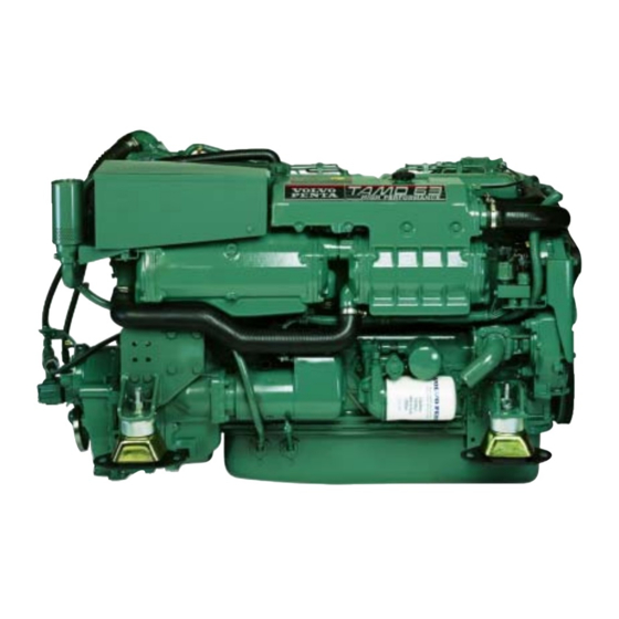
Introduction TAMD63L, -P, TAMD71B, TAMD72P, -WJ The engines are in-line 6 cylinder, direct injection This equipment is not necessary in the TAMD63 and four-stroke engines. They are equipped with a turbo- TAMD72 as they have a different specification, for charger, charge air cooler (CAC) and heat exchang- example, higher compression, a different combustion er for thermostat regulated freshwater cooling. - Page 11 Fig. 1. TAMD63L-A, TAMD63P-A 1. Fine fuel filters 2. Smoke limiter 3. Coolant filler cap 4. Injection pump 5. Oil filler cap 6. Terminal box with semi-automatic fuses 7. Turbocharger 8. Water-cooled exhaust bend (accessory) 9. Reverse gear MPM IRM 220A-1 10.
- Page 12 Fig. 4. TAMD72WJ-A 1. Terminal box with semi-automatic fuses 2. Coolant filler cap 3. Fine fuel filters 4. Smoke limiter 5. Injection pump 6. Oil filler cap 7. Turbocharger 8. Water-cooled exhaust bend (accessory) 9. Stop solenoid 10. Alt. location of oil dipstick 11.
-
Page 13: Instrumentation
The instrument panels used are the main panel, the Flying Bridge (instrument panel for alt. control position) and the auxiliary panel. In addition there is an extra alarm panel. The instrumentation is also supplied separately in sets if Volvo Penta instrument panels are not used. These sets include three smaller panels for starting, stopping and alarm functions. - Page 14 Note! This lamp (14) also works as a bulb failure warning sensor for the starter element.* The lamp comes on even when the key switch is in the I posi- tion (operating position) if there is a fault in the starter element (break).
- Page 15 Auxiliary panel 18. Oil pressure gauge for reverse gear. 19. Blind plugs. Space for extra switches etc. 20. Pressure gauge for turbocharger’s charging pressure. Control panel for auxiliary control position (Flying Bridge) 21. Tachometer, engine speed. Multiply this value by 100 for revolutions per minute 22.
- Page 16 Control panel for pilot house (main panel) 32. Key switch (start lock) with start and stop func- tions and a built-in restart inhibitor (starter motor protection). The restart inhibitor means that new attempts to start can be made only once the key has been returned to the stop position (S).
-
Page 17: Key Switch, Starter Keys
The code must not be divulged to un- authorized persons. Controls Volvo Penta uses two types of controls, single lever and dual lever. With single lever controls, both accel- eration and reverse gear manoeuvers are controlled using one lever, while the dual lever controls have a separate lever for each function. - Page 18 2. Lever for controlling engine speed (rpm) (red handle) Electronic controls (TAMD72P) The Volvo Penta electronic, single-lever control com- bines the functions of a throttle and reverse gear op- eration in one control lever unit. When starting, for example, the shift function can be easily disengaged so that only the engine speed (rpm)* is affected by the lever.
-
Page 19: Calibrating Controls, Tamd72P
Control calibration (TAMD72P) NOTE! If calibration is not carried out after instal- lation, the engine cannot be started. Calibrate first at the Master Control Station fol- lowed by the auxiliary control position(s). The Master Control Station is automatically acti- vated when the key switch is turned to position I (operating position). - Page 20 6. Move the control lever to the position where and turn the key switch to position “I” (operating Astern (rearward) movement throttle opening is to position).* Keep the button pressed in (at least 3 start. Keep the lever in that position (at least 2 seconds) until the yellow indicator lamp begins to seconds) and press the green button (“Neutral”).
- Page 21 8. Single lever control: Return the lever to the neutral position. Dual lever control: Return the levers to the idling and neutral positions. Keep the lever(s) in that position (at least 2 sec- onds) and press the green button (“Neutral”) again.
-
Page 22: Fuel, Lubricating Oils, Coolant
Sulfur content: According to current legislation in When there is a chance of freezing the respective country. Use a mixture of 50% Volvo Penta antifreeze (glycol) Use of fuel with an extremely low sulfur content (Ur- and 50% pure water (as neutral as possible). This... -
Page 23: Operation
Operation Before starting Open the cooling water intake’s sea cock. Check that all the drain cocks are closed and all the drain plugs are fitted. For the positioning of cocks/plugs, see the pictures on pages 28 and 29. Open the fuel cocks. Check that no fuel, water or oil is leaking out. -
Page 24: Starting The Engine
Starting the engine To keep smoke on starting to a minimum, the TAMD71B is fitted with air preheating (a starter element). This starter element is found in the inlet pipe, and its activation time is controlled by a timer relay. In the TAMD63 and TAMD72 engines no starter element is required since these variants have higher compression, different combustion chambers and a modified injection system. - Page 25 Turn the key to position “III” to start (after the indicator lamp has gone out in the case of en- gines with a starter element). Release the key as soon as the engine starts. The key switch has a restart inhibitor. The start- ing procedure must therefore always begin at the “S”...
-
Page 26: Checks During Operation
Checks during operation The normal operating values are: Coolant temperature Oil pressure, engine System voltage 75–95°C TAMD63: 300–550 kPa approx. 14V (12V), or TAMD71, 72: 420–650 kPa 28V (24V) If the oil pressure drops, the temperature rises above the permitted values or there is a loss of charge, the alarm will sound and one of the warning lamps will start to flash to indicate the source of the malfunction. - Page 27 Move the control lever quickly and firmly into reverse, then increase the speed. Note! If the boat has two engines, it is vital that both engines are running, particularly when manoeuvering forwards and backwards. If one engine has not been started and the other is used to reverse, water may enter the stopped engine via the exhaust port and cause serious damage.
-
Page 28: Safety Systems, Tamd72P
Engagement: 1. Stop engine and remove the key from the key switch. 2. Note how the cables are attached to the reverse gear’s solenoids “P”/“S” (Primary/Secondary). Detach the connectors from both solenoids. 3. Remove the solenoid (1) and the valve body (3) for forward (Ahead) from the reverse gear (nor- mally* the valve where the “Primary”... -
Page 29: After Operation
After operation Let the engine idle for a few minutes with the reverse gear in neutral after landing. This will even out the engine temperature and prevent local overheating which may cause the coolant to boil. Turn the key to stop position “S”. Release the key when the engine has stopped (key will spring back automatically into the 0 position). -
Page 30: When There Is A Danger Of Freezing
Action when there is a risk of freezing Check the antifreeze in the freshwater system after the engine has stopped if there is a risk of freezing. See under the heading. “Coolant” on page 20. Drain the water from the seawater system as described below. Check that all the water has drained out. Check the batteries as described on page 67. - Page 31 TAMD63 Note: Remove the cover on the seawater pump. Also remove the hose between the heat exchanger and the reverse gear’s oil cooler, then drain off the coolant while draining the seawater system. F = Freshwater cocks/plugs S = Seawater cocks/plugs V = Venting cock...
-
Page 32: Maintenance And Care Periodic Care And Maintenance
Maintenance Periodic maintenance If your engine and its fittings are to function reliably, periodic maintenance in accordance with the maintenance schedule is required. Several of the items deal with the replacement of consumables such as oil filters, fuel fil- ters, etc. To ensure continued trouble-free use of your engine, it is important always to use original spares. -
Page 34: Maintenance Schedule
Maintenance schedule The description applies generally for all engines unless otherwise stated. If longer oil change intervals are required than those stated below the oil’s condition All operations in the maintenance schedule with the exception of points 17 and 32 must must be tested regularly by the oil manufacturer. - Page 35 No. Action Instructions Info. pge. Remove plug and oil screen. Clean screen and refit parts. Start engine (after filing 6. Twin Disc reverse gear: with oil) and check for leaks. Remove and clean reverse gear oil screen. 7. Replace oil filter in reverse gear Twin Disc Remove clamp (1).
- Page 36 No. Action Instructions Info. pge. A few hours after stopping engine: Drain off water or contaminants through cock/ plug (1). 12. Check/drain extra fuel filter(s). 13. Replace insert(s) in extra Close the fuel cocks at the tank before dismantling the single filter or replacing coarse fuel filter.
- Page 37 No. Action Instructions Info. pge. Close sea cock. Remove cover (1) and lift up insert. Clean insert and housing 18. Check/clean seawater (2). Reinstall parts. Open sea cock and check for leaks. filter. NOTE! The time must be judged by experience after running the engine for a while.
- Page 38 No. Action Instructions Info. pge. Close sea cock before starting work. Drain the water from the seawater system. Replace the anode if more than 50% of it has been used. When fitting, ensure that 24. Check/replace zinc there is good metallic contact between the anode and the material. anode (zinc anodes).
- Page 39 No. Action Instructions Info. pge. Wash the insert in clean diesel. Squeeze it out and place it in the filter housing. Fix the insert by pushing the O-ring down into the groove around the outer edge of the – 30. TAMD63: Clean air insert.
- Page 40 No. Action Instructions Info. pge. Get authorized service personnel to check the condition of the turbocharger and carry out a general check of the engine and its fittings. – 36. Check finish of engine WARNING! Never use high-pressure jets when washing the engine. Never point the water jet at seals, rubber hoses or electrical components.
-
Page 41: Technical Description
Technical description Engine These engines are four-stroke, straight six marine diesel engines with overhead valves. They are fluid-cooled and equipped with turbochargers. The inlet air to the engine is cooled by a seawater-cooled charge air cooler (CAC) after compression in the turbo (TAMD71 and TAMD72 have double charge air coolers). The engines have piston cooling* (oil-cooled pistons). - Page 42 Timing gears The camshaft, oil pump, injection pump, circulation pump (TAMD71 and TAMD72), seawater pump and hydraulic pump (if fitted) are driven by the crankshaft via helical spur gears. Helical spur gear wheels are used in order to keep engine noise to a minimum. Crankcase ventilation The engines have ventilation devices to prevent overpressure and to run off diesel fumes, steam and...
- Page 43 Maintenance – Engine Replacing crankcase ventilation filter TAMD63P and TAMD72P also have a wastegate valve (by-pass valve) installed in the turbine housing. 1. Remove the old filter by unscrewing it counter- The wastegate valve means that the turbocharger is clockwise. optimized for high charging pressure even at low en- 2.
- Page 44 Valve location Inlet Outlet TAMD71, TAMD72: Tensioning drive belts A. Locking screws TAMD71, TAMD72: It should be possible to depress Checking turbocharger the belts 10 mm (0.4") between the pulleys at the This check should be left to authorized service correct tension.
-
Page 45: Lubrication System
Technical description Lubrication System These engines have a forced lubrication system and piston cooling (see “Pistons” on page 39). The oil pump is of the gear-wheel type and is located at the front of the oil sump. This pump is driven by the engine’s timing gears. - Page 46 Lubrication system (partial diagram, filter housing), TAMD63 Pressure pipe to turbocharger 17. Return oil to oil sump via relief 10. Engine oil filter valve 12. Overflow valve 18. Pressure oil via piston cooling 13. Piston cooling valve valve to oil cooler and piston 14.
- Page 47 Maintenance – Lubrication System Oil cooler Oil Change – Engine See the description in the “Cooling system” section The oil should be changed when the engine is on pages 54–55 for information on the oil coolers. hot. WARNING! Hot oil can cause burns. Engines with oil scavenging pump (accessory): Re- move the oil dipstick and connect the suction pipe to the dipstick tube.
- Page 48 Draining oil from the reverse gear TAMD63 1. Engine oil filter 2. Start the engine and run it until the reverse gear 2. By-pass filter reaches operating temperature. 3. Check the oil level with the engine idling and with the neutral position selected. The oil level should reach the upper mark on the dipstick.
-
Page 49: Fuel System
Technical description Fuel system The fuel is drawn up by the feed pump from the fuel tank through the pre-filter(s) and is forced through the fine filters to the injection pump. Excess fuel escapes via the overflow valve back to the tank. This valve is located on the injection pump. - Page 50 The fuel system has two fine fuel filters connected in Pressure-dependent full load stop (smoke limiter)* parallel have the same cover. These filters are dis- TAMD63, TAMD71, TAMD72WJ posable, and the filter insert is made of a spirally The injection pump has a pressure-dependent full wound paper filter.
- Page 51 Maintenance – Fuel System Checking/draining fuel pre-filters Injectors Check the fuel filter and drain off any water and con- The job of the injectors is to atomize and spray the taminants through the drain plug(s) (5). See illustra- fuel, metered precisely by the injection pump, into tion on next page.
- Page 52 Replacing the switchable fine fuel filters 1. Vent screw for left and right filters Double pre-filters 2. Valve knob (normal operating position) 1. Valve knob (both filters 3. Retaining screw on-line in this position) 4. Cover 2. Pressure gauge 5. Drain plug The inserts can be cleaned and replaced while the engine is running.
- Page 53 Venting the fuel system 1. Venting screw on 3. Overflow valve Injectors filter mounting 4. Pressure equalizer 2. Hand pump 1. Protective ring (rubber) 3. Pressure line connection 2. Leak-off fuel line 4. Mounting yoke 3. Pump a further 10–20 strokes with the vent 1.
-
Page 54: Cooling System
Technical description Cooling system These engines are fluid-cooled and have a closed circuit cooling system. The system has two circuits. In the in- ner circuit (the freshwater system), coolant is pumped around by a centrifugal-type coolant pump (circulation pump). In the TAMD63, this pump is driven by the vibration damper via a belt. In other engines, the coolant pump is gear-wheel driven via the timing gears. - Page 55 = Charge air or freshwater = Seawater Flow through charge air cooler (CAC) in the TAMD63 1. Charge air cooler (CAC) Seawater inlet (from sea- 2. Heated charge air from the water pump) turbocharger 5. Seawater outlet (to heat 3. Cooled charge air to the exchanger) Flow through heat exchanger in the TAMD63 engine’s combustion chambers...
- Page 56 Seawater pump The seawater pump is fitted to the timing gear cover at the front of the engine. This pump is driven via the timing gears. The pump impeller is made of rubber and can be replaced. Note: The impeller may be damaged if the pump is run dry.
- Page 57 Maintenance – Cooling System Antifreeze and anti-corrosion, cleaning Oil cooler, reverse gear Close sea cock before working on cooling The reverse gear’s oil cooler is mounted on a bracket system. above the flywheel casing at the rear of the engine. The cooler is connected to the seawater system.
- Page 58 This will evacuate any air remaining in the sys- tem. Seawater filter, checking/cleaning Volvo Penta offers two types of seawater filter. One is a smaller filter with a transparent perspex cover, and the other is larger and has a metal cover.
- Page 59 TAMD63: Charge air cooler (CAC) and insert 1. Screw with drainage hole 2. Plugs over guide balls for CAC insert 4. Remove the cooling water hoses to and from the 14. Connect the plastic pipe from the thermostat heat exchanger/charge air cooler (CAC). housing to the heat exchanger.
- Page 60 5. Lift the inserts. Flush and clean them internally Cleaning oil cooler, reverse gear and externally. Use suitable brushes. Clean Close sea cock before working on cooling housing as well. system. Note: Ensure that no contaminants enter the en- 1. Open the drain cock on the oil cooler. Remove gine’s inlet manifold via the charge air coolers the cooling water pipes to and from the oil cooler.
- Page 61 Replacing the seawater pump impeller Close sea cock before working on cooling system. 1. Remove the pump’s end cover. Pull and twist out the pump impeller using pliers. 2. Clean inside the housing. Lubricate the pump housing and the inside of the cover with a little lu- bricating grease.
-
Page 62: Electrical System
Technical description Electrical system These engines have an electrical system with a generous generator capacity for a normal-sized boat. When an extra power supply is required, we recommend that you fit an extra generator or install a separate generator unit. These engines have a two-pole electrical system with an generator. - Page 63 TAMD71, TAMD72WJ TAMD71, TAMD72WJ Note: The components in the figures are numbered the same as in the engine’s wiring diagrams on pages 73, 75 or 77. 3. Solenoid valve (fuel shut-off 16. Pressure sender, turbo pressure valve)* 17. Oil pressure sender, engine 4.
- Page 64 TAMD72P (EDC) TAMD72P (EDC) Note: The components in the figures are numbered the same as in the engine’s wiring diagrams on pages 79 and 81. 3. Generator (GEN) 4. Starter motor 5. Starter relay 6. Main relay 7. Electronic Diesel Control (EDC) control module box (incl.
- Page 65 This makes it impossible for the pump element to fill up and the engine stops. When supplied by Volvo Penta, the sensor system is not activated. However, it is likely that it was con- This valve is located on a bracket beneath the injection pump.
- Page 66 The main switches should break the current to all Fuses parts consuming electricity. Electrical cables should These engines have two semi-automatic fuses of ap- be routed so they are not exposed to moisture and prox. 8A. These fuses break the current in the event there is no risk of them being exposed to bilgewater of overloading.* in the keelson.
- Page 67 To simultaneously charge two independent bat- tery circuits, fit a Volvo Penta charge distributor to the regular generator (accessory). 2. Batteries Always ensure that the Plus (positive) and Minus (negative) battery leads are correctly installed on the corresponding terminal posts on the batter- ies.
- Page 68 Maintenance – Electrical System NOTE! Always stop the engine and break the current using the main switches before working on the electrical system. Also read the section entitled “Electrical system – Important” on pages 64–65. Resetting/replacing fuses Blade fuse (1) with support (2) for electrical starter el- Ensure that you use the correct size of fuse when ement replacing safety fuses.
- Page 69 Check that the batteries are connected properly. Also check that all other electrical connections are dry and free of oxidation and that there are no loose connections. If necessary, spray these connections with a water-repellent spray (Volvo Penta Universal oil). Optical-type hydrometer...
- Page 70 Stop solenoid Setting the stop solenoid should be left to author- ized service personnel. Incorrect setting may lead to the solenoid burning out. However, a rough check may be carried out as fol- lows: 1. Check that the stop solenoid and its operating le- ver are properly tight.
-
Page 71: Wiring Diagrams
Wiring Diagrams Connecting the charge indicator lamp Extra generator 28V/100A 1. Key switch 2. Charge control lamp Connection of sensor system to standard generator, basic 3. Resistor (47Ω/25W), diagram P/N 863400-8 4. Generator 28V/100A 1. Sensor cable (yellow, 1.5 mm 6. - Page 74 TAMD71B, TAMD72WJ-A Control panel for auxiliary control position (Flying Bridge) Up to and including engine No. 207181083/xxxx* Cable areas in mm are given following the color codes *Engines fitted with a stop solenoid (applies to the engine’s wiring diagram). in the wiring diagrams. The cable area is 1.0 mm unless otherwise stated.
- Page 76 TAMD71B As of and including engine Control panel for auxiliary control position (Flying Bridge) No. 207181084/xxxx* *Engines fitted with a fuel shut-off valve Cable areas in mm are given following the color codes (applies to the engine’s wiring diagram). in the wiring diagrams. The cable area is 1.0 mm unless otherwise stated.
- Page 77 6. Connection to connector (18) on main panel NO = Normally open during operation The cable run marked with a dashed line is not supplied by Volvo Penta. Cable color Conversions mm /AWG* Blue LBL =...
- Page 78 TAMD72WJ-A As of and including engine No. Control panel for auxiliary control position (Flying Bridge) 207181084/xxxx* Cable areas in mm are given following the color codes *Engines fitted with a fuel shut-off valve (applies to the engine’s wiring diagram). in the wiring diagrams. The cable area is 1.0 mm unless otherwise stated.
- Page 79 6. Connection to connector (18) on main panel NO = Normally open during operation The cable run marked with a dashed line is not supplied by Volvo Penta. Cable color Conversions mm /AWG* Blue OR =...
- Page 80 TAMD72P-A (12V) Cable areas in mm are noted after the color codes in the wiring diagrams. Control panel for auxiliary control position (Flying Bridge) Spring loaded The cable area is 1.0 mm unless otherwise stated. Conversions mm /AWG Spring loaded 16 (17) 15 (16) Instrument panel, (Main panel)
- Page 81 Light blue Brown SB = Black The cable area is 0.5 mm unless LBN = Light brown VO = Violet otherwise stated. Green White The cable run marked with a dashed Gray Yellow line is not supplied by Volvo Penta. Orange...
- Page 82 TAMD72P-A (24V) Cable areas in mm are noted after the color codes in the wiring diagrams. Control panel for auxiliary control position (Flying Bridge) Spring loaded The cable area is 1.0 mm unless otherwise stated. Conversions mm /AWG 16 (17) 15 (16) Spring loaded Instrument panel, (Main panel)
- Page 83 Light blue Brown SB = Black The cable area is 0.5 mm unless LBN = Light brown VO = Violet otherwise stated. Green White Gray Yellow The cable run marked with a dashed Orange line is not supplied by Volvo Penta.
- Page 85 Flying Bridge instrument kit 1. Control module (alarm) 2. Connector for connecting extra warning display (accessory) 3. Warning light, engine coolant temperature (ECT) 4. Warning light, oil pressure 5. Warning lamp, charging 6. Control lamp, pre-heating(TAMD71B) 7. Alarm 8. Alarm test/acknowledgement switch 9.
- Page 86 TAMD72P-A Single control position – Single or dual lever Single control position – Single or dual lever controls controls with control adapters Multiple control positions – Single or dual lever Multiple control positions – Single or dual lever controls with control adapters controls Cable color Location diagram (all wiring diagrams)
-
Page 87: Inhibiting
Inhibiting Stop the engine and drain or pump the lubricat- WARNING! Observe the following when clean- ing oil from the oil sump. Connect the regular ing with high-pressure water jets. Never point fuel lines. the water jet at seals, rubber hoses or electrical components. -
Page 88: Bringing Out Of Storage
Bringing out of storage 4. If necessary, fill the engine with lubricating oil of the correct quality. Fit a new oil filter if this has 1. Remove any protective cover over the engine, air not been done when changing the oil during in- intake and exhaust pipe. -
Page 89: Troubleshooting
Troubleshooting 1. Engine does not start Starter motor does not turn engine over CAUSE REMEDY The reverse gear is not disengaged (applies to Put the reverse gear control lever into neutral control with neutral position switch) TAMD72P: The controls have not been calibrated Calibrate controls as per instructions on pages 17–... - Page 90 Starter motor turns over as normal but engine does not start CAUSE REMEDY Air in fuel system Vent the fuel system as shown on page 50 No fuel – fuel cocks closed Open the fuel cocks – fuel tank empty/wrong tank on line Fill with fuel/connect the correct fuel tank –...
- Page 91 2. Engine starts but stops again/runs unevenly CAUSE REMEDY Air in fuel system Vent the fuel system as shown on page 50 No fuel – fuel cocks closed Open the fuel cocks – fuel tank empty/wrong tank on line Fill with fuel/connect the correct fuel tank –...
- Page 92 4. Coolant temperature too low CAUSE REMEDY Install a new thermostat Faulty thermostat 5. Engine does not reach correct speed at wide open throttle (WOT) CAUSE REMEDY Boat abnormally loaded If possible, reduce/redistribute the load Fouling on bottom of boat Clean the bottom of the boat and treat it with anti- fouling paint Faulty/damaged propeller...
- Page 93 6. Engine runs on CAUSE REMEDY Replace the fuse (16A for 12V, or 8A for 24V system TAMD71, -72WJ: Stop solenoid fuse defective voltage). (pos. 7 in wiring diagram page 73) One of the semi-automatic fuses in the junction Reset the fuse by pressing in the button. box has tripped (pos.
- Page 94 Diagnostic functions – OBD system (TAMD72P) DIAGNOSIS The indicator lamp in the yellow Diagnosis button on the EDC system control panel starts to flash if the system receives abnormal signals or if there is a mal- function in the EDC system. Press the button for at least one second in order to read off the Diagnostic Trouble Code (DTC) and to cancel the alarm.
-
Page 98: Technical Data
Technical Data General TAMD63L-A, TAMD71B TAMD72P-A, TAMD63P-A TAMD72WJ-A No. of cylinders ............Swept volume ............5.48 dm (liters), 6.73 dm (liters), 6.73 dm (liters), (334 in (411 in (411 in Low idle ..............600 ±20 rpm 600 ±30 rpm 600 ±30 rpm*... - Page 99 Fuel system TAMD63L-A, TAMD71B TAMD72P-A, TAMD63P-A TAMD72WJ-A Injection pump, settings, TAMD63L and TAMD71B ........16° ±0.5° BTDC 22° ±0.5° BTDC – TAMD63P and TAMD72P ........15° ±0.5° BTDC – 15° ±0.5° BTDC TAMD72WJ ............– – 18° ±0.5° BTDC Injectors, opening pressure, TAMD63L and TAMD71B ........
- Page 100 Cooling system TAMD63L-A, TAMD71B TAMD72P-A, TAMD63P-A TAMD72WJ-A Freshwater system capacity incl. heat exchanger, approx................ 27 liters (5.9 Imp. gals/ 35 liters (7.7 Imp. gals/ 7.1 US gals) 9.3 US gals) Thermostat starts to open at ........73–77°C (163–171°F) 73–77°C (163–171°F) fully open at ..........
- Page 101 TAMD63L-A, TAMD71B TAMD72P-A TAMD63P-A Twin Disc Type designation ............MG5061A MG5061A – Gear ratios ..............2.01:1 1.75:1; 2.01:1; – 2.47:1 Angle (output shaft) ............ 7° – Oil capacity, approx........... 3.2 liters (0.7 Imp. gals/ – 0.85 US gals) Oil quality (as per API system) .........
- Page 102 TAMD63L-A, TAMD71B TAMD72P-A TAMD63P-A Type designation ............– MG507A–1 MG507A–1(E*) Gear ratios ..............– 1.51:1; 1.77:1; 1.98:1 Angle (output shaft) ............ – 7° Oil capacity, approx........... – 6.7 liters (1.5 Imp. gals/ 1.8 US gals) Oil quality (as per API system) .........
-
Page 103: Accessories
Below is a range of products which can be pur- chased as accessories Note: Not all accessories can be fitted to all en- gines. Ask your Volvo Penta service dealer for advice. Volvo Penta lubricating oils: – VDS*, SAE 15W/40... - Page 104 Hot water outlet: Location of angle nipples with cock (Thread: 1/2"–14 NPTF) TAMD63 TAMD71, TAMD72 A. Angle nipple and cock (inlet) A. Angle nipple and cock (outlet) Exhaust riser Extra power take-off at the front of the engine (TAMD71B engines in commercial operation): Muffler Pulley, mounted on crankshaft.
- Page 105 Accessories Controls Dual lever control The control lever on Volvo Penta controls has an ad- The brake is for the engine speed control. justable friction brake. This allows the lever weighting Adjust the friction by turning the screw at the arrow to be adapted to the personal needs of the owner.
- Page 106 Owner Name: ................Tel.: ........Address: ..........................Nearest Volvo Penta Service Dealer Name: ................Tel.: ........Address: ..........................Engine information Engine type: ........................Serial No..........................Reverse gear type/No......................Disengageable clutch type/No....................
Need help?
Do you have a question about the TAMD63L and is the answer not in the manual?
Questions and answers