Table of Contents
Advertisement
Quick Links
Contents
2020-03-25
Operating manual
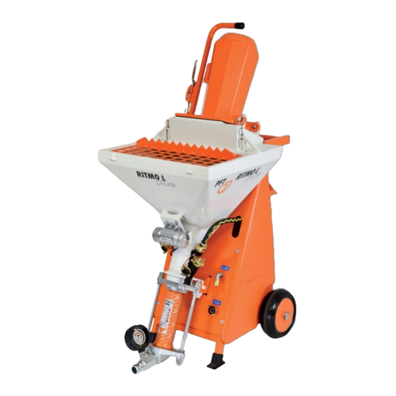
Mixing pump RITMO L FC-230V plus powercoat
Part 2 EC Declaration of Conformity
Overview – Operation
Item number of operating manual: 00132861
Item number of the parts list machine 00667998: RITMO L FC-230V plus powercoat, 1 Ph, 50 Hz,
2,2 kW
Item number of the parts list machine 00659659: RITMO L FC-230V plus powercoat, 1 Ph, 50 Hz,
2,2 kW
Item number of the parts list machine 00659661: RITMO L FC-230V plus powercoat, 1 Ph, 50 Hz,
2,2 kW without spraying gun
Item number of the parts list machine 00631075: RITMO L FC-230V powercoat – A 2-2,5, 1 Ph, 50
Hz without spraying gun
Read the operating manual prior to beginning any work!
Advertisement
Table of Contents

Related Manuals for PFT RITMO L FC-230V plus


Summary of Contents for PFT RITMO L FC-230V plus
- Page 1 Overview – Operation Item number of operating manual: 00132861 Item number of the parts list machine 00667998: RITMO L FC-230V plus powercoat, 1 Ph, 50 Hz, 2,2 kW Item number of the parts list machine 00659659: RITMO L FC-230V plus powercoat, 1 Ph, 50 Hz,...
- Page 2 © Knauf PFT GmbH & Co.KG Postfach 60 97343 Iphofen Einersheimer Straße 53 97346 Iphofen Germany Tel. +49 9323 31-760 Fax +49 9323 31-770 Technical hotline: +49 9323 31-1818 info@pft.net www.pft.net 2020-03-25...
-
Page 3: Table Of Contents
5.4 Operating requirements ......10 18.3 Purpose of flowmeter ......19 5.5 Connection values for water ....10 19 Description of the PFT pressure booster pump (accessories) ........20 6 Sound power level .......... 10 19.1 Application area of pressure booster pump .......... - Page 4 Part 2 EC Declaration of Conformity Overview – Operation Contents 26 Transport, packaging and storage ....25 39 Potentiometer ..........35 26.1 Safety instructions for transport ... 25 40 Mortar hoses ..........36 26.2 Closing the motor tilt flange ....25 40.1 Preparing the mortar hoses ....
- Page 5 Part 2 EC Declaration of Conformity Overview – Operation Contents 50.3 Switching on the machine again after 56.1 Placing the machine on its rear .... 57 a power failure ........46 56.2 Removing the pump unit ...... 57 56.3 Remove the suction flange ....58 51 Measures in case of water failure ....
-
Page 6: Ec Declaration Of Conformity
Agent responsible for putting together the relevant technical documentation: Dipl.-Wirtsch.-Ing. Michael Duelli, Einersheimer Straße 53, 97346 Iphofen, Germany. The technical documentation is held at: Knauf PFT GmbH & Co.KG, Technische Abteilung, Einersheimer Straße 53, 97346 Iphofen, Germany. Iphofen, Germany Dr. York Falkenberg... -
Page 7: Testing
Part 2 EC Declaration of Conformity Overview – Operation Testing 2 Testing 2.1 Testing by machine operator Before the start of each work shift, the machine operator must test the effectiveness of the control and safety devices as well as check the proper attachment of all protective devices. ... -
Page 8: Spare Part Lists
Part 2 EC Declaration of Conformity Overview – Operation Spare part lists 4 Spare part lists You can find spare part lists for the machine in the Internet under www.pft.net 4.1 Accessories 2020-03-25... -
Page 9: Technical Data
Part 2 EC Declaration of Conformity Overview – Operation Technical data 5 Technical data 5.1 General specifications Specification Value Unit Weight RITMO L plus powercoat 120 kg Length with pump 915 mm Width 600 mm Overall height 1450 mm Individual weights Specification Value Unit Chassis / Frame... -
Page 10: Operating Requirements
Part 2 EC Declaration of Conformity Overview – Operation Sound power level 5.4 Operating requirements Ambient conditions Specification Value Unit Temperature range 2 - 45 °C Relative humidity (maximum) 80 % Operating period Specification Value Unit Maximum continuous operating period 8 hours 5.5 Connection values for water Specification... -
Page 11: Dimensions
Part 2 EC Declaration of Conformity Overview – Operation Dimensions 9 Dimensions Fig. 2: Dimensions 10 Type plate The type plate contains the following information: Manufacturer Type Year built Machine number Permissible operating pressure Fig. 3: Type plate 11 Quality control sticker The quality control sticker contains the following information: CE confirmed in compliance with EU directives Serial number... -
Page 12: Structure Ritmo L Plus Powercoat
Part 2 EC Declaration of Conformity Overview – Operation Structure RITMO L plus powercoat 12 Structure RITMO L plus powercoat 12.1 Overview RITMO L plus Fig. 5: Overview RITMO L plus powercoat 1 Engine guard 11 Pressure flange 2 Gear motor 12 Mortar hose connection 3 Motor guard plate 13 Mortar pressure gauge... -
Page 13: View From Rear Ritmo L Plus
Fig. 6: View from rear 13 Assembles RITMO L plus 13.1 Gear motor with material hopper and pump unit The mixing pump PFT RTIMO L plus powercoat comprises the following main components: Gear motor with tilt flange, mixing tube with material hopper,... -
Page 14: Chassis With Compressor And Control Box
Part 2 EC Declaration of Conformity Overview – Operation Description of assemblies 13.3 Chassis with compressor and control box Chassis with water manifold and control box. Weight: 51.2 kg. Fig. 9: Frame 14 Description of assemblies 14.1 Overview of control box RITMO L plus powercoat 1. -
Page 15: Overview Of Water Manifold Ritmo L Plus
Part 2 EC Declaration of Conformity Overview – Operation Connections RITMO L plus 14.2 Overview of water manifold RITMO L plus 1. Pressure reducer 2. Water pressure monitor. 3. Water connection from water supply. 4. Water to mixing tube. 5. Shut-off valve / water outlet. 6. -
Page 16: Mortar Hose Connection
Part 2 EC Declaration of Conformity Overview – Operation Operating modes 15.2 Mortar hose connection 1. Mortar hose connection (1) to mortar pressure gauge (2). Fig. 13: Mortar hose connection 16 Operating modes 16.1 Pump motor selector switch The pump motor has three operating modes: Selector switch position “0”: The machine is switched off. -
Page 17: Accessories For Machine
Part 2 EC Declaration of Conformity Overview – Operation Accessories for machine 17 Accessories for machine Power cable 3x2.5 mm², 25 m safety socket CEE 16A Art.No.20423420 Fig. 17 Tool bag, mixing pump RITMO L plus powercoat Art.No. 00098808 Consisting of: Tool roll bag 350 x 400 Art.No. -
Page 18: Intended Use Of Fitting Block
Part 2 EC Declaration of Conformity Overview – Operation Intended use of fitting block Cleaner coupling 13 female part Geka Art.No. 00087597 Fig. 22 Air hose DN9 Ewo male part | Ewo female part - 16 m Art.No. 00008521 Fig. 23 00094898 Spraying gun powercoat DN13 VA4 1500 Ewo, handle, stainless steel... -
Page 19: Purpose Of Solenoid Valve
Part 2 EC Declaration of Conformity Overview – Operation Intended use of fitting block 18.2 Purpose of solenoid valve Application range! The flowmeter serves for measuring the volume of transparent liquid and gas flows in closed pipes. Optionally, the devices can also be used for flow monitoring. -
Page 20: Description Of The Pft Pressure Booster Pump (Accessories)
The water supply is automatically ensured from a water tank by the PFT pressure booster pump for the constant water supply to the PFT machine engineering. The flow pressure of min. 2.5 bar when the machine is running is ensured on size by drawing water from the water tank. -
Page 21: Preparation Of Pressure Booster Pump (Accessories)
21 Initial operation, filling the pump Before putting the PFT High Pressure Pump into operation for the first time, fill the pump with water so that the air in the pump housing is displaced. - Page 22 Part 2 EC Declaration of Conformity Overview – Operation Initial operation, filling the pump The end of the suction line (1) must be fitted with an inlet strainer with filter screen and integral non-return valve. An additional fine filter in the suction line is recommended. NOTE! The delivery of the pump decreases with increasing suction line length.
-
Page 23: Brief Description Of Ritmo L Plus Powercoat
Brief description of RITMO L plus powercoat 22 Brief description of RITMO L plus powercoat The proven mixing pump PFT RITMO L plus powercoat is equipped with a revolutionary stainless steel remixer, which makes it possible for the first time to grind nodules mechanically. -
Page 24: Material
It is recommended to reduce the length of the mortar hose if you exceed an operating pressure of 20 bar. To avoid machine breakdowns and excessive wear on pump motor, mixing shaft and pump, always use original PFT spare parts such as: PFT rotors ... -
Page 25: Transport, Packaging And Storage
Part 2 EC Declaration of Conformity Overview – Operation Transport, packaging and storage 26 Transport, packaging and storage 26.1 Safety instructions for transport Improper transport CAUTION! Damage can be caused by improper transport! Significant damage may occur if the equipment is transported incorrectly. -
Page 26: Closing The Snap Lock Before Transport
Part 2 EC Declaration of Conformity Overview – Operation Transport, packaging and storage 26.3 Closing the snap lock before transport CAUTION! Generally make sure that the snap lock (1) on the gear motor and on the material hopper is closed when the machine is moving. -
Page 27: Transport By Car
Part 2 EC Declaration of Conformity Overview – Operation Packaging 26.6 Transport by car DANGER! Risk injury due to unsecured load! All persons involved in the loading are responsible for securing the load properly during road transport. The relevant vehicle driver is responsible for the operational loading. -
Page 28: Operation
Part 2 EC Declaration of Conformity Overview – Operation Operation Handling the packaging materials CAUTION! Environmental damage can result from improper disposal of materials! Packaging materials are valuable resources and can often be reused or recycled. Therefore: Dispose of packaging materials in an environmentally sound manner. -
Page 29: Preparation Of The Machine
Part 2 EC Declaration of Conformity Overview – Operation Preparation of the machine All machine operators must wear the following protective equipment: Personal protective equipment Protective work clothing Safety goggles Safety gloves Safety shoes Ear protection NOTE! The warning signs illustrated relate to additional protective equipment that must be worn for particular working conditions. -
Page 30: Connection To The 230V Power Supply
Part 2 EC Declaration of Conformity Overview – Operation Connection to the 230V power supply 30 Connection to the 230V power supply 30.1 Connection to power distributor Only connect machine (1) to power distributors that conform to regulations. DANGER! Danger of death due to electric current! The electrical connection must be fused correctly: For the operation of frequency converters,... -
Page 31: Water Supply Connection
Part 2 EC Declaration of Conformity Overview – Operation Connection to the 230V power supply 30.4 Water supply connection 1. Check whether the water inlet screen in the water inlet (1) is clean. 2. Clean and bleed the water hose (2) for the water mains supply. 3. -
Page 32: Switching On Ritmo L Plus
Part 2 EC Declaration of Conformity Overview – Operation Switching on RITMO L plus 31 Switching on RITMO L plus 31.1 Putting RITMO L plus into operation 1. Selector switch (1) at the middle position. 2. Turn the main switch (2) to the “I” position. 3. -
Page 33: Watering The Mixing Zone
Part 2 EC Declaration of Conformity Overview – Operation Mortar pressure gauge 31.3 Watering the mixing zone NOTE! The pump must generally be flushed with water. Flushing with water makes it easier for the pump to start up. 1. Connect the water hose (1) from the water fitting to the rubber mixing tube. -
Page 34: Dustcatcher Ritmo L Plus Set
Part 2 EC Declaration of Conformity Overview – Operation DUSTCATCHER RITMO L plus SET 34 DUSTCATCHER RITMO L plus SET DUSTCATCHER for RITMO L plus SET item number 00611177 comprising: Dust collector class M. Supplementary set for dust collector M. ... -
Page 35: Putting The Machine Into Operation
Part 2 EC Declaration of Conformity Overview – Operation Putting the machine into operation 38 Putting the machine into operation 38.1 Checking the mortar consistency 1. Connect consistency inspection tube to the mortar pressure gauge. 2. Place a bucket or tray below the consistency inspection tube. Item number: 00099057 Consistency inspection tube 25M-part. -
Page 36: Mortar Hoses
Part 2 EC Declaration of Conformity Overview – Operation Mortar hoses 40 Mortar hoses 40.1 Preparing the mortar hoses 1. Connect the cleaner coupling (1) to the shut-off valve (2). 2. Connect the mortar hose (3) to the cleaner coupling (1). 3. -
Page 37: Compressed Air Supply
(7). Fig. 62: Remote control cable 41.3 Switching on the air compressor 1. Switch on air compressor (air compressor PFT LK 402 IV Art.No. 00233174). 2. As soon as the air compressor has built up pressure in the pipe system, it switches off via the pressure cut-off. -
Page 38: Switching On The Vibrator
Part 2 EC Declaration of Conformity Overview – Operation Switching on the vibrator 42 Switching on the vibrator NOTE! If the material is not to slide subsequently in the material hopper, the vibrator can be connected. 1. Plug the connector of the vibrator into the grey Fig. -
Page 39: Opening The Air Tap On The Spray Gun
Part 2 EC Declaration of Conformity Overview – Operation Applying mortar 43.1 Opening the air tap on the spray gun 1. Turn the selector switch Pump motor directions of rotation (1) to the right. 2. Point the spray gun toward the wall to be plastered. 3. -
Page 40: In The Event Of A Work Stoppage / Pause
Part 2 EC Declaration of Conformity Overview – Operation Working with pastes 43.3 In the event of a work stoppage / pause 1. Release the handle (1) on the sprayer 2. The machine stops 3. Close the air valve (2) when the nozzle on the sprayer is freely blown Fig.69: Closing the air valve 4. -
Page 41: Mortar Hose
Part 2 EC Declaration of Conformity Overview – Operation Mortar hose 45 Mortar hose 45.1 Prepare mortar hose 1. Connect the Cleaner coupling (1) to the water tap (2) 2. Connect mortar hose (3) and water it. 3. Remove the mortar hose and the cleaner coupling again. 4. -
Page 42: Filling The Material Hopper With Pastes
Part 2 EC Declaration of Conformity Overview – Operation Filling the material hopper with pastes 46 Filling the material hopper with pastes DANGER! Risk of injury from bag opener! Sharp edges of the bag opener pose a risk of injury. ... -
Page 43: Switching On The Air Compressor
Part 2 EC Declaration of Conformity Overview – Operation Applying material 47.3 Switching on the air compressor 3. Switch on air compressor (air compressor PFT LK 402 IV Art.No. 00233174). 4. As soon as the air compressor has built up pressure in the pipe system, it switches off via the pressure cut-off. -
Page 44: Opening The Air Valve On The Spray Gun
Part 2 EC Declaration of Conformity Overview – Operation Applying material NOTE! Before the first spraying cycle, it is recommended to run the machine briefly without spray nozzle until material has emerged from the spray head. Then screw the nozzle back onto the spray head. The delivery pressure may rise to 30 bar for a short time, but will fall back to the normal working pressure of 12-15 bar after a short running time. -
Page 45: Shutting Down In An Emergency
Part 2 EC Declaration of Conformity Overview – Operation Shutting down in an emergency 49 Shutting down in an emergency 49.1 Emergency OFF switch Switching off in an emergency Machine movements and the energy supply must be disabled as quickly as possible in dangerous situations. Proceed as follows in the event of an emergency: 1. -
Page 46: Discharging Mortar Pressure
Part 2 EC Declaration of Conformity Overview – Operation Measures to be taken in the event of a power failure 50.2 Discharging mortar pressure DANGER! Overpressure on the machine! When opening machine components, these can fly open in an uncontrolled manner and injure the operator. -
Page 47: Measures In Case Of Water Failure
Part 2 EC Declaration of Conformity Overview – Operation Measures in case of water failure 51 Measures in case of water failure HINWEIS! The machine can be supplied with clean water from a tank using a pressure booster pump (article number 00493686) (see page 20/21 Fig. -
Page 48: Safety
Part 2 EC Declaration of Conformity Overview – Operation Troubleshooting 52.4 Safety Personal protective equipment Wear the following protective equipment for all maintenance work: Protective work clothing. Protective goggle, protective gloves, safety shoes, ear protection. Personnel Unless otherwise stated, the troubleshooting methods detailed here can be carried out by the machine operator. - Page 49 Part 2 EC Declaration of Conformity Overview – Operation Troubleshooting Malfunction Possible cause Solution Performed by Water not Solenoid valve (bore hole in Clean the solenoid valve Service technician flowing membrane blocked) (flowmeter Solenoid coil defective Replace the solenoid coil Service technician does not display...
-
Page 50: Pumping Stopped / Blockage
Inner wall of mortar hose defective Replace mortar hose Operator Rotor too deep in pressure flange Replace pressure flange Service technician Part not original PFT spare part Use an original PFT spare part Service technician Water level Backpressure in mortar hose... -
Page 51: Causes Of Clogged Hoses
Part 2 EC Declaration of Conformity Overview – Operation Clearing hose blockages 53.2 Causes of clogged hoses: Heavily worn mortar hoses Interruptions in work Poorly lubricated mortar hoses, Residual water in mortar hose Clogging of pressure flange ... -
Page 52: Risk Of Injury To Due Overpressure
5. Remove blockage by tapping or shaking at the point of the blockage. 6. If necessary, introduce a flushing hose into the mortar hose and flush out the material (PFT flushing hose item no. 00113856). Fig. 90: Detaching the coupling 2020-03-25... -
Page 53: Switching On The Machine After Removing A Blockage
Part 2 EC Declaration of Conformity Overview – Operation End of shift / Cleaning 54.3 Switching on the machine after removing a blockage 1. Selector switch (1) at “Zero” position (middle position). 2. Close the air tap on spray gun. 3. -
Page 54: Checking The Mortar Pressure
Part 2 EC Declaration of Conformity Overview – Operation End of shift / Cleaning 55.3 Checking the mortar pressure The machine must be cleaned daily after work and before prolonged pauses. To switch off the machine: 1. Turn the selector switch (1) to the “Zero” position (middle position). -
Page 55: Coupling The Water Hose
Part 2 EC Declaration of Conformity Overview – Operation End of shift / Cleaning 4. Remove fine plaster nozzle (5) from the spray gun. 5. Open water outlet valve Pos. 2 Fig. 93, until the sponge ball emerges at the spray gun. 6. -
Page 56: Inserting The Mixing Tube Cleaner
Part 2 EC Declaration of Conformity Overview – Operation End of shift / Cleaning 55.7 Inserting the mixing tube cleaner 1. Insert cleaner shaft and mixing tube cleaner (1) into the mixing tube. NOTE! Insert mixing tube cleaner (1) with the scrapers pointing downwards. -
Page 57: Replacing The Pump / Cleaning The Pump
Part 2 EC Declaration of Conformity Overview – Operation Replacing the pump / Cleaning the pump 56 Replacing the pump / Cleaning the pump 56.1 Placing the machine on its rear DANGER! Danger of death due to unauthorised restarting! When working on the machine, there is a danger of unauthorised switching on of the electrical supply. -
Page 58: Remove The Suction Flange
Part 2 EC Declaration of Conformity Overview – Operation Switching off RITMO powercoat 56.3 Remove the suction flange 1. Uncouple the water hose (1) from the rubber mixing tube (2). 2. Undo screw (3) for the pressure flange (4). 3. Remove and clean the suction flange (4). 4. -
Page 59: Measures To Be Taken If There Is A Risk Of Frost
Part 2 EC Declaration of Conformity Overview – Operation Measures to be taken if there is a risk of frost 58 Measures to be taken if there is a risk of frost CAUTION! Damage due to frost! Water that expands on freezing inside the component can cause serious damage. -
Page 60: Blowing The Water Manifold Dry
Part 2 EC Declaration of Conformity Overview – Operation Maintenance 58.1 Blowing the water manifold dry 1. Disconnect the water hose (1) from the rubber mixing tube 2. Connect air hose (2) from air compressor to water inlet Fig. 109: Connecting the air hose 58.2 Blowing the water manifold dry 1. -
Page 61: Removing The Connection Cable
Part 2 EC Declaration of Conformity Overview – Operation Maintenance Basic information WARNING! Danger of injury due to improperly performed maintenance work! Improper maintenance can lead to serious injuries or equipment damage. Therefore: Keep the assembly area clean and tidy. Unattached components or tools left lying around or stacked on one another can cause accidents. -
Page 62: Environmental Protection
Part 2 EC Declaration of Conformity Overview – Operation Maintenance tasks 59.3 Environmental protection Observe the following environmental protection guidelines when carrying out maintenance work: Remove used, leaking or excess grease from all manual lubrication points and dispose of it correctly according to the applicable local regulations. -
Page 63: Dirt Trap Screen In The Water Inlet
Part 2 EC Declaration of Conformity Overview – Operation Maintenance tasks 60.3 Dirt trap screen in the water inlet Check the dirt trap screen in the water inlet on a daily basis: 2. Remove the dirt trap screen from the Geka coupling. 3. -
Page 64: After Performing Maintenance
Part 2 EC Declaration of Conformity Overview – Operation Disassembly 60.6 After performing maintenance 1. After maintenance has been completed, carry out the following steps before switching on again: 2. Check that all previously loosened screw connections have a tight fit. 3. -
Page 65: Disassembly
Part 2 EC Declaration of Conformity Overview – Operation Disposal Electrical system DANGER! Danger of death due to electric current! Contact with live components can lead to death or serious injury. Live electrical components can move uncontrollably and cause serious injury. Therefore: ... -
Page 66: Index
Assemblies RITMO L plus ......... 13 Dealing with malfunctions ........47 Description of assemblies ........14 Blowing the water manifold dry ......60 Description of the PFT pressure booster pump (accessories) ..........20 Brief description of RITMO L plus powercoat ..23 Dimensions ............11 Dirt trap screen.......... - Page 67 Part 2 EC Declaration of Conformity Overview – Operation Index Gear motor............13 Opening the air tap on the spray gun ....39 Gear motor with material hopper and pump unit 13 Opening the air valve on the spray gun ....44 General information ..........
- Page 68 Part 2 EC Declaration of Conformity Overview – Operation Index Putting RITMO L plus into operation ....32 Switching on the air compressor ......43 Putting the machine into operation ....35 Switching on the machine after removing a blockage ............53 Putting the pressure booster pump into operation ...............
-
Page 69: Notes
Part 2 EC Declaration of Conformity Overview – Operation Notes 64 Notes 2020-03-25... - Page 70 Part 2 EC Declaration of Conformity Overview – Operation 2020-03-25...
- Page 71 Part 2 EC Declaration of Conformity Overview – Operation 2020-03-25...
- Page 72 Part 2 EC Declaration of Conformity Overview – Operation PFT - THE FLOW OF PRODUCTIVITY Knauf PFT GmbH & Co. KG Postfach 60 97343 Iphofen Einersheimer Straße 53 97346 Iphofen Germany Tel. +49 9323 31-760 Fax +49 9323 31-770 Technical hotline: +49 9323 31-1818 info@pft.net...
Need help?
Do you have a question about the RITMO L FC-230V plus and is the answer not in the manual?
Questions and answers