Panasonic CS-E10KD3EA Service Manual
Hide thumbs
Also See for CS-E10KD3EA:
- Service manual (105 pages) ,
- Operating instructions manual (92 pages)
Table of Contents
Advertisement
Quick Links
Please file and use this manual together with the service manual for Model No. CU-2E15LBE CU-2E18LBE
CU-3E18LBE CU-4E23LBE, Order No. PHAAM1003090C3 and CS-ME10CKPG CS-ME12CKPG CS-ME14CKPG
CS-ME18CKPG CS-ME7CKPG CU-2E15CBPG CU-2E18CBPG CU-3E23CBPG CU-4E27CBPG Order No.
RAC0209005C2
TABLE OF CONTENTS
1 Safety Precautions----------------------------------------------- 3
2 Specifications ----------------------------------------------------- 5
2.1. CS-E10KD3EA CU-E10HBEA ------------------------- 5
2.2. CU-2E15LBE ----------------------------------------------- 8
2.3. CU-2E18LBE ----------------------------------------------- 9
2.4. CU-3E18LBE ----------------------------------------------10
2.5. CU-4E23LBE ---------------------------------------------- 11
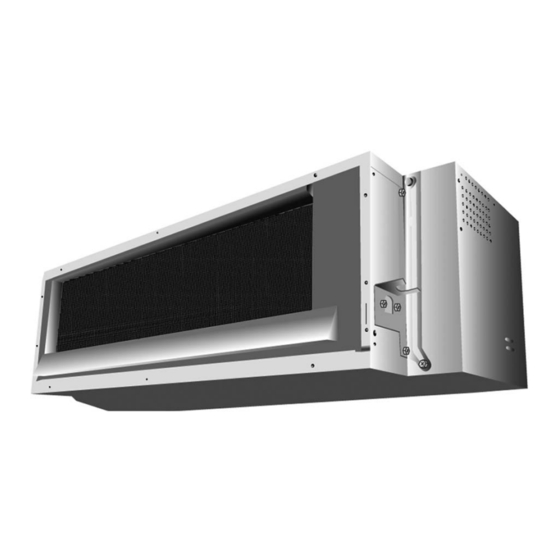
Indoor Unit
CS-E10KD3EA
PAGE
2.6. CU-4E27CBPG ------------------------------------------- 12
3 Features------------------------------------------------------------ 20
4 Location of Controls and Components------------------ 21
4.1. Indoor Unit ------------------------------------------------- 21
4.2. Outdoor Unit----------------------------------------------- 21
4.3. Remote Control------------------------------------------- 21
5 Dimensions ------------------------------------------------------- 22
© Panasonic HA Air-Conditioning (M) Sdn. Bhd. 2010.
Unauthorized copying and distribution is a violation of law.
Order No. PHAAM1003092C2
Air Conditioner
Outdoor Unit
CU-E10HBEA
PAGE
Advertisement
Table of Contents

Subscribe to Our Youtube Channel
Related Manuals for Panasonic CS-E10KD3EA


Summary of Contents for Panasonic CS-E10KD3EA
-
Page 1: Table Of Contents
2.3. CU-2E18LBE ----------------------------------------------- 9 4.2. Outdoor Unit----------------------------------------------- 21 2.4. CU-3E18LBE ----------------------------------------------10 4.3. Remote Control------------------------------------------- 21 2.5. CU-4E23LBE ---------------------------------------------- 11 5 Dimensions ------------------------------------------------------- 22 © Panasonic HA Air-Conditioning (M) Sdn. Bhd. 2010. Unauthorized copying and distribution is a violation of law. - Page 2 5.1. Indoor Unit & Remote Control ------------------------ 22 5.2. Outdoor Unit ----------------------------------------------- 23 6 Refrigeration Cycle Diagram -------------------------------- 24 7 Block Diagram --------------------------------------------------- 25 8 Wiring Connection Diagram --------------------------------- 26 8.1. Indoor Unit ------------------------------------------------- 26 8.2. Outdoor Unit ----------------------------------------------- 27 9 Electronic Circuit Diagram----------------------------------- 28 9.1.
-
Page 3: Safety Precautions
1 Safety Precautions • Read the following “SAFETY PRECAUTIONS” carefully before perform any servicing. • Electrical work must be installed or serviced by a licensed electrician. Be sure to use the correct rating of the power plug and main circuit for the model installed. •... - Page 4 19. During installation, install the refrigerant piping properly before run the compressor. (Operation of compressor without fixing refrigeration piping and valves at opened condition will cause suck-in of air, abnormal high pressure in refrigeration cycle and result in explosion, injury etc.). 20.
-
Page 5: Specifications
2 Specifications 2.1. CS-E10KD3EA CU-E10HBEA MODEL INDOOR CS-E10KD3EA OUTDOOR CU-E10HBEA Performance Test Condition EUROVENT / AS Phase, Hz Single, 50 Power Supply Min. Mid. Max. Min. Mid. Max. 0.60 2.50 3.00 0.60 2.50 3.00 Capacity BTU/h 2050 8530 10200 2050... - Page 6 MODEL INDOOR CS-E10KD3EA OUTDOOR CU-E10HBEA Type Sirocco Material ABS + GF 10% Motor Type DC Motor (8-poles) Output Power Cool 1000 Heat 1040 Cool 1070 Heat 1100 Cool 1185 Speed Heat 1235 Cool 1300 Heat 1370 Cool 1400 Heat 1440...
- Page 7 MODEL INDOOR CS-E10KD3EA OUTDOOR CU-E10HBEA Fin Material Aluminium (Pre Coat) Fin Type Louver Fin Indoor Heat Row × Stage × FPI 2 × 8 × 20 Exchanger Size (W × H × L) 620 × 203.2 × 44 Fin Material...
-
Page 8: Cu-2E15Lbe
2.2. CU-2E15LBE Item Unit OUTDOOR UNIT Indoor Unit Combination 2.5kW + 2.5kW Power Source 1 Phase, 230V, 50Hz (Power supply from outdoor unit) 4.5 (1.5 ~ 5.2) Capacity BTU/h 15300 (5120 ~ 17700) Running Current 5.75 Electrical Cooling Operation Power Input 1.23 (0.25 ~ 1.52) Data 3.66 (6.00 ~ 3.42) -
Page 9: Cu-2E18Lbe
2.3. CU-2E18LBE Item Unit OUTDOOR UNIT Indoor Unit Combination 3.2kW + 3.2kW Power Source 1 Phase, 230V, 50Hz (Power supply from outdoor unit) 5.2 (1.5 ~ 5.4) Capacity BTU/h 17700 (5120 ~ 18400) Running Current 7.10 Electrical Cooling Operation Power Input 1.52 (0.25 ~ 1.58) Data 3.42 (6.00 ~ 3.42) -
Page 10: Cu-3E18Lbe
2.4. CU-3E18LBE Item Unit OUTDOOR UNIT Indoor Unit Combination 2.0kW + 2.0kW + 5.0kW Power Source 1 Phase, 230V, 50Hz (Power supply from outdoor unit) 5.2 (1.8 ~ 7.3) Capacity BTU/h 17700 (6140 ~ 24900) Running Current Electrical Cooling Operation Power Input 1.20 (0.36 ~ 2.18) Data... -
Page 11: Cu-4E23Lbe
2.5. CU-4E23LBE Item Unit OUTDOOR UNIT Indoor Unit Combination 2.0kW + 2.0kW + 2.0kW + 5.0kW Power Source 1 Phase, 230V, 50Hz (Power supply from outdoor unit) 6.8 (1.9 ~ 8.8) Capacity BTU/h 23200 (6480 ~ 30000) Running Current Electrical Cooling Operation Power Input 1.68 (0.34 ~ 2.47) -
Page 12: Cu-4E27Cbpg
2.6. CU-4E27CBPG Item Unit OUTDOOR UNIT Indoor Unit Combination 3.2kW + 3.2kW + 3.2kW + 4.0kW Power Source Single Phase, 230V, 50Hz (Power supply from outdoor unit) Capacity 8.0 (3.0 - 9.2) Running Current 8.70 Electrical Power Input 1980 (530 - 2870) Data Cooling Operation 4.04... - Page 13 • Multi Split Combination Possibility: - A single outdoor unit enables air conditioning of up to two separate rooms for CU-2E15LBE, CU-2E18LBE. - A single outdoor unit enables air conditioning of up to three separate rooms for CU-3E18LBE. - A single outdoor unit enables air conditioning of up to four separate rooms for CU-4E23LBE, CU-4E27CBPG.
- Page 14 • Outdoor Unit : CU-2E15LBE • Outdoor Unit : CU-2E18LBE...
- Page 15 • Outdoor Unit : CU-3E18LBE...
- Page 16 • Outdoor Unit : CU-4E23LBE...
- Page 18 • Outdoor Unit : CU-4E27CBPG...
-
Page 20: Features
3 Features • Inverter Technology - Wider output power range - Energy saving - Quick Cooling - Quick Heating - More precise temperature control • Environment Protection - Non-ozone depletion substances refrigerant (R410A) • Long Installation Piping - Long piping up to 20 meter (E10HBEA) •... -
Page 21: Location Of Controls And Components
4 Location of Controls and Components 4.1. Indoor Unit 4.2. Outdoor Unit 4.3. Remote Control... -
Page 22: Dimensions
5 Dimensions 5.1. Indoor Unit & Remote Control... -
Page 23: Outdoor Unit
5.2. Outdoor Unit... -
Page 24: Refrigeration Cycle Diagram
6 Refrigeration Cycle Diagram... -
Page 25: Block Diagram
7 Block Diagram... -
Page 26: Wiring Connection Diagram
8 Wiring Connection Diagram 8.1. Indoor Unit... -
Page 27: Outdoor Unit
8.2. Outdoor Unit... -
Page 28: Electronic Circuit Diagram
9 Electronic Circuit Diagram 9.1. Indoor Unit... -
Page 29: Outdoor Unit
9.2. Outdoor Unit... -
Page 30: Printed Circuit Board
10 Printed Circuit Board 10.1. Indoor Unit 10.1.1. Main Printed Circuit Board... -
Page 31: Outdoor Unit
10.2. Outdoor Unit 10.2.1. Main Printed Circuit Board... - Page 32 10.2.2. CPU Printed Circuit Board...
-
Page 33: Installation Instruction
11 Installation Instruction Attached accessories Required Materials • Read the catalog and other technical materials and prepare the required materials. • Applicable piping kit CZ-3F5, 7BP (E10****), CZ-4F5, 7, 10BP (E15****, E18****) Other Items to be Prepared (Locally Purchased) Product name Remarks Rigid PVC pipe VP20 (outer diameter ø26);... -
Page 34: Indoor Unit
11.1. Indoor Unit 11.1.1. SELECTING THE INSTALLATION LOCATION Take into consideration the following contents when creating the blueprint. Indoor unit installation location • Do not install the unit in excessive oil fume area such as kitchen, workshop and etc. • The location should be strong enough to support the main unit without vibration. •... - Page 35 11.1.3. INSTALLING THE INDOOR UNIT (INSTALLATION EMBEDDED IN THE CEILING) • Always provide sufficient entry and exit space to allow installation work, inspection and unit replacement. • Waterproof the rear surface of the ceiling below the unit in consideration of water droplets forming and dropping. When cooling operation is performed for an extended period under the following conditions, water droplets may form and drop.
- Page 36 PREPARING TO INSTALL THE INDDOR UNIT • Fit the drain hose insulation around the drain hose as shown in the diagram beside. • Attach the discharge chamber. ( ) (10 screws) • Cut out the intake cut-out portions at the unit rear panel using a cutter or other tools to make openings. •...
- Page 37 1. Embed an outlet box (JIS C 8336) into the wall. Outlet box maybe purchased separately. Medium size square outlet box (obtain locally) Part No. DS3744 (Panasonic Co., Ltd.) or equivalent. 2. Secure the remote controller lower case to the outlet box with the two accessory screws .
- Page 38 B. IF REMOTE CONTROLLER CABLE IS EXPOSED 1. Install the remote controller lower case to the wall with the two accessory screws 2. Fasten the screws properly until screw head is lower than the rib and reach the base of remote controller lower case to ensure they do not damage the PCB inside the remote controller 3.
- Page 39 CHECK THE DRAINAGE Check after connecting the power supply. • Pour approximately 600 cc of water into the drain pan of the main unit using a squeeze bottle, etc. • Press the drain test run switch on the control board in the control box to start the drain motor and check whether the water drains normally.
-
Page 40: Outdoor Unit
11.1.6.1. WIRE STRIPPING AND CONNECTING REQUIREMENT 11.2. Outdoor Unit 11.2.1. SELECTING THE INSTALLATION LOCATION • If an awning is built over the unit to prevent direct sunlight or rain, be careful that heat radiation from the condenser is not obstructed. •... - Page 41 11.2.3. CONNECTING THE PIPING Connecting The Piping To Indoor Unit Please make flare after inserting flare nut (locate at joint portion of indoor piping) onto the copper pipe. (In case of using long piping) Connect the piping • Align the center of piping and sufficiently tighten the flare nut with fingers.
- Page 42 11.2.4. EVACUATION OF THE EQUIPMENT (FOR EUROPE & OCEANIA DESTINATION) WHEN INSTALLING AN AIR CONDITIONER, BE SURE TO EVACUATE THE AIR INSIDE THE INDOOR UNIT AND PIPES in the following procedure. 1. Connect a charging hose with a push pin to the Low and High side of a charging set and the service port of the 3-way valve. •...
- Page 43 (FOR DETAIL REFER TO WIRING DIAGRAM AT UNIT) 1. Remove the control board cover from the unit by loosening the screw. 2. Connecting cable between indoor unit and outdoor unit shall be approved polychloroprene sheathed 4 × 1.5 mm flexible cord, type designation 245 IEC 57 or heavier cord.
- Page 44 CHECK ITEMS Is there any gas leakage at flare nut connections? Is the Earth wire connection done properly? Has the heat insulation been carried out at flare nut Is the power supply voltage complied with the rated value? connections? Is there any abnormal sound emitted? Is the connecting cable being fixed firmly to the terminal board? Is the cooling / heating operation normal? Is the connecting cable being clamped firmly?
-
Page 45: Operation And Control
12 Operation and Control 12.1. Basic Function Inverter control, which equipped with a microcomputer in determining the most suitable operating mode as time passes, automatically adjusts output power for maximum comfort always. In order to achieve the suitable operating mode, the microcomputer maintains the set temperature by measuring the temperature of the environment and performing temperature shifting. - Page 46 12.1.5. Automatic Operation • This mode can be set using remote control and the operation is decided by remote control setting temperature, remote control operation mode, indoor intake air temperature and outdoor air temperature. • During operation mode judgment, indoor fan motor (with speed of Lo-) and outdoor fan motor are running for 30 seconds to detect the indoor intake and outdoor air temperature.
-
Page 47: Quiet Operation (Cooling Mode/Cooling Area Of Soft Dry Mode)
B. Feedback control • Immediately after the fan motor started, feedback control is performed once every second. • During fan motor on, if fan motor feedback 2550 rpm or < 50 rpm continue for 10 seconds, then fan motor error counter increase, fan motor is then stop and restart. -
Page 48: Powerful Mode Operation
12.2.1. Quiet operation (Heating) A. Purpose To provide quiet heating operation compare to normal operation. B. Control condition a. Quiet operation start condition • When “quiet” button at remote control is pressed. Quiet LED illuminates. b. Quiet operation stop condition 1. -
Page 49: Timer Control
12.4. Timer Control 12.4.1. ON Timer Control ON timer can be set using remote control, the unit with timer set will start operate earlier than the setting time. This is to provide a comfortable environment when reaching the set ON time. 60 minutes before the set time, indoor (at fan speed of Lo-) and outdoor fan motor start operate for 30 seconds to determine the indoor intake air temperature and outdoor air temperature in order to judge the operation starting time. -
Page 50: Protection Control
13 Protection Control 13.1. Protection Control For All Operations 13.1.1. Restart Control (Time Delay Safety Control) • The Compressor will not turn on within 3 minutes from the moment operation stops, although the unit is turned on again by pressing OFF/ON button at remote control within this period. •... -
Page 51: Protection Control For Cooling & Soft Dry Operation
13.1.4. IPM (Power transistor) Prevention Control A. Overheating Prevention Control 1. When the IPM temperature rises to 110°C, compressor operation will stop immediately. 2. Compressor operation restarts after three minutes the temperature decreases to 95°C. B. DC Peak Current Control 1. - Page 52 13.2.2. Cooling Overload Control i. Pipe temperature limitation/restriction • Detects the Outdoor pipe temperature and carry out below restriction/limitation (Limit the compressor Operation frequency) • The compressor stop if outdoor pipe temperature exceeds 63°C. • If the compressor stops 4 times in 20 minutes, Timer LED blinking (F95: outdoor high pressure rise protection) 13.2.3.
-
Page 53: Protection Control For Heating Operation
13.3. Protection Control For Heating Operation 13.3.1. Intake Air Temperature Control Compressor will operate at maximum frequency if below conditions occur: 1. When the indoor intake air temperature is 30°C or above. 13.3.2. Outdoor Air Temperature Control The maximum current value is regulated when the outdoor air temperature rises above 14°C in order to avoid compressor overloading. -
Page 54: Servicing Mode
14 Servicing Mode 14.1. TEST RUN OPERATION (FOR PUMP DOWN/SERVICING PURPOSE) • The Test Run operation will be activated by short-circuiting CN-S at outdoor unit PCB after applying power between the terminal 1 and 2. The unit forced to run rated frequency cooling operation mode. -
Page 55: Troubleshooting Guide
15 Troubleshooting Guide 15.1. Refrigeration Cycle System In order to diagnose malfunctions, make sure that there are no electrical problems before inspecting the refrigeration cycle. Such problems include insufficient insulation, problem with the power source, malfunction of a compressor and a fan. The normal outlet air temperature and pressure of the refrigeration cycle depends on various conditions, the standard values for them are shown in the table on the right. -
Page 56: Relationship Between The Condition Of The Air Conditioner And Pressure And Electric Current
15.2. Relationship Between The Condition Of The Air Conditioner And Pressure And Electric Current Cooling Mode Heating Mode Condition of the air conditioner Low Pressure High Pressure Electric current Low Pressure High Pressure Electric current during operation during operation Insufficient refrigerant (gas leakage) Clogged capillary tube or Strainer... -
Page 57: Breakdown Self Diagnosis Function
15.3. Breakdown Self Diagnosis Function 15.3.1. Self Diagnosis Function (Three Digits Alphanumeric Code) • Once abnormality has occurred during operation, the unit will stop its operation, and OFF/ON operation LED OFF. • OFF indicator does not shown on remote control display. •... -
Page 58: Error Codes Table
15.4. Error Codes Table Diagnosis Abnormality Emergency Abnormality / Protection control Primary location to verify display Judgement operation No abnormality detected — Normal operation — Indoor / outdoor abnormal communication > 1 min. after start- Indoor fan • Internal / external cable connections ing operation operation only •... -
Page 59: Self-Diagnosis Method
15.5. Self-diagnosis Method 15.5.1. H11 (Indoor/Outdoor Abnormal Communication) Malfunction Decision Conditions • During startup and operation of cooling and heating, the data received from outdoor unit in indoor unit signal transmission is checked whether it is normal. Malfunction Caused • Faulty indoor unit PCB. •... - Page 60 15.5.2. H12 (Indoor/Outdoor Capacity Rank Mismatched) Malfunction Decision Conditions • During startup, error code appears when different types of indoor and outdoor units are interconnected. Malfunction Caused • Wrong models interconnected. • Wrong indoor unit or outdoor unit PCBs mounted. •...
- Page 61 15.5.3. H14 (Indoor Intake Air Temperature Sensor Abnormality) Malfunction Decision Conditions • During startup and operation of cooling and heating, the temperatures detected by the indoor intake air temperature sensor are used to determine sensor errors. Malfunction Caused • Faulty connector connection. •...
- Page 62 15.5.4. H15 (Compressor Temperature Sensor Abnormality) Malfunction Decision Conditions • During startup and operation of cooling and heating, the temperatures detected by the outdoor compressor temperature sensor are used to determine sensor errors. Malfunction Caused • Faulty connector connection. • Faulty sensor. •...
- Page 63 15.5.5. H16 (Outdoor Current Transformer Open Circuit) Malfunction Decision Conditions • A current transformer (CT) is detected by checking the compressor running frequency ( rated frequency) and CT detected input current (less than 0.65A) for continuously 20 seconds. Malfunction Caused •...
- Page 64 15.5.6. H19 (Indoor Fan Motor – DC Motor Mechanism Locked) Malfunction Decision Conditions • The rotation speed detected by the Hall IC during fan motor operation is used to determine abnormal fan motor (feedback of rotation > 2550rpm or < 50rpm). Malfunction Caused •...
- Page 65 15.5.7. H23 (Indoor Pipe Temperature Sensor Abnormality) Malfunction Decision Conditions • During startup and operation of cooling and heating, the temperatures detected by the indoor heat exchanger temperature sensor are used to determine sensor errors. Malfunction Caused • Faulty connector connection. •...
- Page 66 15.5.8. H24 (Indoor Pipe Temperature Sensor 2 Abnormality) Malfunction Decision Conditions • During startup and operation of cooling and heating, the temperatures detected by the indoor heat exchanger temperature sensor 2 are used to determine sensor errors. Malfunction Caused • Faulty connector connection. •...
- Page 67 15.5.9. H27 (Outdoor Air Temperature Sensor Abnormality) Malfunction Decision Conditions • During startup and operation of cooling and heating, the temperatures detected by the outdoor air temperature sensor are used to determine sensor errors. Malfunction Caused • Faulty connector connection. •...
- Page 68 15.5.10. H28 (Outdoor Pipe Temperature Sensor Abnormality) Malfunction Decision Conditions • During startup and operation of cooling and heating, the temperatures detected by the outdoor pipe temperature sensor are used to determine sensor errors. Malfunction Caused • Faulty connector connection. •...
- Page 69 15.5.11. H30 (Compressor Discharge Temperature Sensor Abnormality) Malfunction Decision Conditions • During startup and operation of cooling and heating, the temperatures detected by the outdoor discharge pipe temperature sensor are used to determine sensor errors. Malfunction Caused • Faulty connector connection. •...
- Page 70 15.5.12. H97 (Outdoor Fan Motor – DC Motor Mechanism Locked) Malfunction Decision Conditions • The rotation speed detected by the Hall IC during fan motor operation is used to determine abnormal fan motor. Malfunction Caused • Operation stops due to short circuit inside the fan motor winding. •...
- Page 71 15.5.13. H98 (Indoor High Pressure Protection) Error Code will not display (no Timer LED blinking) but store in EEPROM Malfunction Decision Conditions • During heating operation, the temperature detected by the indoor pipe temperature sensor is above 60°C. Malfunction Caused •...
- Page 72 15.5.14. H99 (Indoor Freeze Prevention Protection: Cooling or Soft Dry) Error code will not display (no TIMER LED blinking) but store in EEPROM Malfunction Decision Conditions • Freeze prevention control takes place (when indoor pipe temperature is lower than 2°C). Malfunction Caused •...
- Page 73 15.5.15. F11 (4-way valve Abnormality) Malfunction Decision Conditions • When heating operation, when indoor pipe temperature is below 10°C. • When cooling operation, when indoor pipe temperature is above 45°C. Malfunction Caused • Connector in poor contact. • Faulty sensor. •...
- Page 74 15.5.16. F90 (Power Factor Correction Protection) Malfunction Decision Conditions • During startup and operation of cooling and heating, when Power Factor Correction (PFC) protection circuitry at the outdoor unit main PCB senses abnormal high DC voltage level. Malfunction Caused • DC voltage peak due to power supply surge. •...
- Page 75 15.5.17. F91 (Refrigeration Cycle Abnormality) Malfunction Decision Conditions • During cooling, compressor frequency = Fcmax. • During heating, compressor frequency > Fhrated. • During cooling and heating operation, running current: 0.65A < I < 1.65A. • During cooling, indoor intake - indoor pipe < 4°C. •...
- Page 76 15.5.18. F93 (Compressor Rotation Failure) Malfunction Decision Conditions A compressor rotation failure is detected by checking the compressor running condition through the position detection circuit. Malfunction Caused • Compressor terminal disconnect. • Outdoor PCB malfunction. • Compressor malfunction. Troubleshooting...
- Page 77 15.5.19. F95 (Cooling High Pressure Abnormality) Malfunction Decision Conditions During operation of cooling, when outdoor unit heat exchanger high temperature data (61°C) is detected by the outdoor pipe temperature sensor. Malfunction Caused • Air short circuit at outdoor unit. • Dust accumulation on the outdoor unit heat exchanger. •...
- Page 78 15.5.20. F96 (IPM Overheating) Malfunction Decision Conditions During operating of cooling and heating, when IPM temperature data (100°C) is detected by the IPM temperature sensor. Multi Models Only • Compressor Overheating: During operation of cooling and heating, when the compressor OL is activated. •...
- Page 79 15.5.21. F97 (Compressor Overheating) Malfunction Decision Conditions During operation of cooling and heating, when compressor tank temperature data (112°C) is detected by the compressor tank temperature sensor. Malfunction Caused • Refrigerant shortage (refrigerant leakage). • 2/3 way valve closed. • Detection error due to faulty compressor tank temperature sensor. Troubleshooting...
- Page 80 15.5.22. F98 (Input Over Current Detection) Malfunction Decision Conditions During operation of cooling and heating, when an input over-current (15.06A) is detected by checking the input current value being detected by current transformer (CT) with the compressor running. Malfunction Caused •...
- Page 81 15.5.23. F99 (Output Over Current Detection) Malfunction Decision Conditions During operation of cooling and heating, when an output over-current (20.2A) is detected by checking the current that flows in the inverter DC peak sensing circuitry. Malfunction Caused • DC peak due to compressor failure. •...
-
Page 82: Disassembly And Assembly Instructions
16 Disassembly and Assembly Instructions WARNING High Voltage are generated in the electrical parts area by the capacitor. Ensure that the capacitor has discharged sufficiently before proceeding with repair work. Failure to heed tis caution may result in electric shocks. 16.1. - Page 83 16.1.3. Detaching the Fan 1. First detach the Upper and Inner Casing (16.1.1) 2. Disengage the 4 catches (2 each on the left and right) on the Air Guide. 3. Use a 2.5 mm hexagonal wrench to loosen the 2 bolts connecting the Fan Motor and Fan, detach the shaft connecting the Fan Motor and Fan, loosen the screw holding the Fan and detach the Fan.
- Page 84 16.1.5. Outdoor Electronic Controller Removal Procedure 1. Remove the top panel and front panel • Be save to return the wiring to its original position • There are many high voltage components within the heat sink cover so never touch the interior during operation. Wait at least two minutes after power has been turned off.
-
Page 85: Technical Data
17 Technical Data 17.1. Operation Characteristics... -
Page 89: Sensible Capacity Chart
17.2. Sensible Capacity Chart CS-E10KD3EA CU-E10HBEA Outdoor Temp. (°C) Indoor wet bulb temp. 17.0°C 2.48 1.88 0.62 2.32 1.80 0.67 2.16 1.73 0.72 1.96 1.65 0.77 19.0°C 2.50 0.68 19.5°C 2.72 1.97 0.63 2.55 1.89 0.68 2.37 1.82 0.73 2.15 1.73... -
Page 90: Exploded View And Replacement Parts List
18 Exploded View and Replacement Parts List 18.1. Indoor Unit Note: The above exploded view is for the purpose of parts disassembly and replacement. The non-numbered parts are not kept as standard service parts. - Page 91 REF NO. DESCRIPTION & NAME QTY. CS-E10KD3EA REMARKS OVER LOAD PROTECTOR CWA12161 FUSE-COMPLETE CWA16C1038 TERMINAL BOARD ASS'Y CWA28K1045J SENSOR-COMPLETE CWA50C2556 WIRED REMOTE CONTROL COMPLETE (WITH CABLE) CWA75C3408 WIRED REMOTE CONTROL CWA75C3375 FAN MOTOR DC 30W 3PH ARW41G8P30AC FIN & TUBE EVAPORATER-COMPLETE...
-
Page 92: Outdoor Unit
18.2. Outdoor Unit Note: The above exploded view is for the purpose of parts disassembly and replacement. The non-numbered parts are not kept as standard service parts. - Page 93 REF. NO. DESCRIPTION & NAME QTY. CU-E10HBEA REMARKS CHASSY ASS’Y CWD50K2176 FAN MOTOR BRACKET CWD541089 SCREW - FAN MOTOR BRACKET CWH551217 FAN MOTOR ARW44W8P40AC SCREW - FAN MOTOR MOUNT CWH55252J PROPELLER FAN ASSY CWH03K1014 NUT - PROPELLER FAN CWH56053J COMPRESSOR 5CS110XBD04 ANTI-VIBRATION BUSHING CWH50077...
Need help?
Do you have a question about the CS-E10KD3EA and is the answer not in the manual?
Questions and answers