Table of Contents
Advertisement
Quick Links
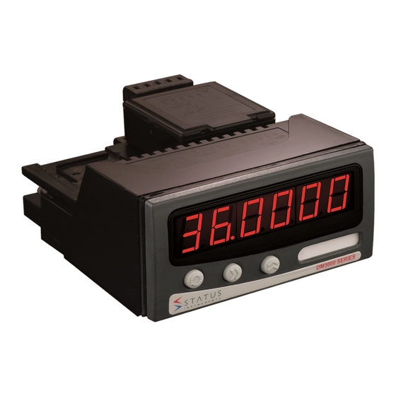
DM3600A
Single Channel Universal Input
6 Digit Indicator with Flow Totalizer Functions
Status Instruments Ltd, Status Business Park, Tewkesbury, Glos. GL20 8FD
Tel: +44 (0)1684 296818
Email: sales@status.co.uk
Important - Please read this document
before any installing.
52-314-2358-02 Issue: Web 4
Fax: +44 (0)1684 293746
Web: www.status.co.uk
I N D E X
SECTION
CONTENTS
1.0
2.0
3.0
4.0
5.0
6.0
7.0
SPECIFICATION
8.0
9.0
10.0
11.0
12.0
13.0
14.0
15.0
PAGE NO.
1
1
2-3
4-5
5
6-7
7-10
10-11
11-12
13
13
14-17
18-20
21-22
23
Advertisement
Table of Contents

Related Manuals for Status Instruments DM3600A


Summary of Contents for Status Instruments DM3600A
-
Page 1: Table Of Contents
OUTPUT MENU STRUCTURE 18-20 14.0 SYSTEM MENU STRUCTURE 21-22 15.0 FAULT FINDING Status Instruments Ltd, Status Business Park, Tewkesbury, Glos. GL20 8FD Tel: +44 (0)1684 296818 Fax: +44 (0)1684 293746 Email: sales@status.co.uk Web: www.status.co.uk Important ‐ Please read this document before any installing. 52-314-2358-02 Issue: Web 4... -
Page 2: Description
1.0 DESCRIPTION 3.0 INSTALLATION (Read the following safety information before installation) The DM3600 is a highly accurate and stable digital process indicator that accepts all commonly used process signals. The unit can be used "stand alone" or with the Modbus serial communications option, as part of a WARNING ! larger system. -
Page 3: Option Pods
3.3 POWER SUPPLY 4.0 OPTION PODS The power supply rating will be indicated on the top of the instrument, ENSURE IT IS CORRECT FOR THE 4.1 INSTALLING PODS APPLICATION. THE MAINS SUPPLY TO THE EQUIPMENT MUST BE PROTECTED BY AN EXTERNAL 1 A FUSE AND A SUITABLE Power must be removed from unit before adding/removing a pod. -
Page 4: Configuration Options
4.3 ISOLATED (4 TO 20) mA RE-TRANSMISSION POD. POD-3000/03 6.0 MECHANICAL DETAILS The re-transmission pod (when fitted) is designed to provide (0 to 10) mA, (0 to 20) mA or (4 to 20) mA output Material ABS/PC in active or passive modes. The output can be any portion of the display. The pod can be used in two Flammability IEC707 FV0, UL 94VO modes:... - Page 5 6.2 OPTION POD (All dimensions shown in mm) THERMOCOUPLE DM3600 5 WAY I/P CONNECTION TYPE RANGE (°C) -200 to 1370 19.5 16.0 -200 to 1200 13.5 53.5 -210 to 400 R*³ -10 to 1760 0 to 1700 S*³ -10 to 1760 -200 to 1000 43.5 -100 to 600...
-
Page 6: Mechanical
REMOTE DIGITALS OPTION 7.2 COMMUNICATIONS OPTION Two isolated digital inputs are available to reset latched alarms, clear peak/valley readings, or for customised use with TFML. RS485 Modbus Communications CONNECTIONS DM3600 is available with RS485 serial communications using MODBUS RTU protocol, and can be configured Input 5 way tension clamp connector (2 Part) using Status’... -
Page 7: Menu Mode
8.2 RUN MODE OPTIONS 9.1 GENERAL MENU NAVIGATION The diagram below describes how to move around the menu structure and enter data. More specifically it details: 1. How to enter a real number If enabled this If enabled this will 2. -
Page 8: Menu Map
10.0 MENU MAP 12.0 INPUT MENU STRUCTURE tYPE uOLt CUrEnt Displayed if voltage input is selected InPUt Input type Voltage Thermocouple Current FROM The input sub-menu is where the input to the unit is Displayed if current input is selected InPUt RUN MODE selected and configured. - Page 9 12.1 INPUT MENU BLOCKS ENGINEERING LOW / HIGH If ‘Stndrd’ scaling is chosen, the user will encounter ‘En9 LO’ and ‘En9 HI’ entries, in order to manually scale the input to the relevant input_lo and input_hi values (see table overleaf for input_lo/hi values). The TYPE PV_lo &...
-
Page 10: Output Menu Structure
OUT OF RANGE ACTION 13.0 OUTPUT MENU STRUCTURE When an input goes out of range, the following occurs: RELAY OUTPUT MENU If fitted, any relays go into alarm state If fitted, the re-transmission current derived from the out of range alarm input goes to 3.8 mA or OUt 1 Output 1 21.12 mA, depending on whether the burnout setting is set to low or high, respectively. - Page 11 13.1 OUTPUT MENU FUNCTION BLOCKS RELAY SENSE The ‘Inurt’ setting refers to the relay sense during powered operation. All other relay output menu settings refer to the alarm state. When in alarm, the relevant front panel LED is lit. 13.2 RELAY OUTPUT MENU POWER ALARM STATUS Inurt SETTING RELAY POSITION (A) RELAY POSITION (B) The relay menu shown is for alarm A.
-
Page 12: System Menu Structure
14.0 SYSTEM MENU 14.1 SYSTEM MENU FUNCTION BLOCKS The system menu opposite allows the communications to and from the device to be configured and also MODBUS DEVICE ADDRESS allows various functions to be enabled from the run mode. The passcode can also be changed from within This sets the address for the RS485 communications. -
Page 13: Fault Finding
Press all three front panel keys together READING HIGH NOW displayed 6 low digits of the total and check the 6 high total digits Status Instruments Ltd, Status Business Park, Tewkesbury, Glos. GL20 8FD SHOWS A LOW VALUE Tel: +44 (0)1684 296818 Fax: +44 (0)1684 293746 Email: sales@status.co.uk...
Need help?
Do you have a question about the DM3600A and is the answer not in the manual?
Questions and answers