
Related Manuals for Status Instruments DM4500U


Summary of Contents for Status Instruments DM4500U
- Page 1 PROCESS CONTROL TEMPERATURE AND LOAD CELL INDICATOR INSTRUCTION MANUAL DM4500U Page 1 of 54...
- Page 2 Page 2 of 54...
-
Page 3: Table Of Contents
INDEX OVERVIEW ..................4 1.1. Introduction to DM4500U..............4 GETTING STARTED ................. 5 2.1. Power supply and connectors .............. 9 2.2. Instrument front panel ............... 11 2.3. Programming instructions ..............11 INPUT CONFIGURATION..............13 3.1. Process input Programming..............15 3.1.1. -
Page 4: Overview
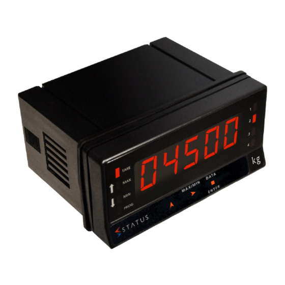
1. OVERVIEW 1.1 Introduction to model DM4500U The DM4500U model is a digital multifunction instrument which allows the user to program the input as a: - PROCESS INPUT (V, mA) - LOAD CELL INPUT (mV) - Pt100 INPUT - THERMOCOUPLE INPUT (J, K, T) The basic instrument is a soldered assembly composed of a main board, a tricolor programmable display and a power circuit. -
Page 5: Getting Started
2. GETTING STARTED Packing contents Instruction manual Digital panel meter DM4500U Accessories for panel mounting (sealing gasket and fixing clips). Accessories for wiring connections (plug-in terminal block connectors with a fingertip key). Wiring label (fixed to the product housing). Legend label with engineering units. - Page 6 Dimensions and mounting Front: 96 x 48 mm Depth: 60 mm Panel cut-out: 92 x 45 mm CLEANING: Front cover should be cleaned only with a soft cloth soaked in neutral soap product. DO NOT USE SOLVENTS Page 6 of 54...
- Page 7 Programming the instrument. First, connect the instrument to the corresponding supply; automatically, a display test will be done and the software version will be shown, then the instrument will go to run mode. Next, press the key to enter into the programming mode; the indication "-Pro-"...
- Page 8 Access to programmed parameters Because of the menu structure, the programming routines allow access to change one parameter without passing through the whole list of parameters. To advance through programming Progress through programming routines is done by pressing key. In general, push key a certain number of times to select an option and push key to validate the change and to go forward...
-
Page 9: Power Supply And Connectors
Selecting an option from the list When the parameter is an option to be chosen among different possibilities, the key allows you to browse through the list of options until you find the desired parameter. 2.1 – Power Supply and connectors WARNING: If not installed and used in accordance with these instructions, protection against hazards may be impaired. - Page 10 WIRING and POWER SUPPLY RANGE DM4500/S1 (85 to 265) VAC (50 to 60) Hz, or (100 to 300) VDC DM4500/S2 (22 to 53) VAC (50 to 60) Hz, or (10.5 to 70) VDC Pin 1: Live Pin 2: Neutral CONNECTORS CN1 To perform wiring connections, strip the wire leaving between (7 and 10) mm exposed and insert it in the required terminal while...
-
Page 11: Instrument Front Panel
2.2 –Instrument frontal view 2.3 – Programming guide To programme the product to accept different sensor types, please see the sections below. To save time we have marked paragraphs as obligatory (O), recommendable (R) or optional (op). As Process indicator: Input Configuration (Sec. - Page 12 As thermometer thermocouple: Input Configuration (Sec. 3.4) (O). Input Connection (Sec. 3.4.1) (O). Program remote inputs (Sec. 5.2) (R). Install and configure output option(s) (Sec. 7) (op). Programming lock-out (Sec. 6) (R). Page 12 of 54...
- Page 13 CnInP tEMP ProC LoAd 10 V 20 mA 15 mV 30 mA Pt 100 - tC - - Pro - °C °F - J - - K - - T - - Pro - Process: Input type 1 °C - °C - - °F - 0.1 °C Load Cell:...
- Page 14 Top Level (Programming menu entry point) CnInp Level 1 Channel Input; for selecting the correct type of input configuration for the sensor to be used. Options available; Proc, LoAd, tEMP Proc Level 2 LoAd Level 2 (See Sec. 3.1) (See Sec. 3.2) Process input type selection.
-
Page 15: Process Input Programming
3.1 – Program process input When used as a process indicator, the parameter to configure is the input type, in volts (-10 to 10) Vdc range or in milliamperes (-20 to 20) mA range. 3.1.1 – Sensor connection (V, mA) Refer to wiring guidelines in (Sec. -
Page 16: Wiring Diagram For Ma Input
3.1.2 WIRING DIAGRAM FOR INPUT Ma (±0 to 20) mA / (4 to 20) mA SENSOR (0 to 20) mA (4 to 20) mA SENSOR (0 to 20) mA (4 to 20) mA SENSOR (4 to 20) mA SENSOR SENSOR (0 to 20) mA (0 to 20) mA (4 to 20) mA... -
Page 17: Wiring Diagram For V Input
3.1.3 WIRING DIAGRAM FOR INPUT V (±0 to 10) V SENSOR (0 to 10) V SENSOR SENSOR (0 to 10) V (0 to 10) V SENSOR (0 to 10) V SENSOR (0 to 10) V Page 17 of 54... -
Page 18: Load Cell Input Programming
3.2 – Programming of Load cell input Refer to cell manufacturer’s documentation, particularly with respect to the cell sensitivity and supply voltage specifications. As load cell indicator, the meter’s function is to measure forces (weight, pressure, torque...) applied to a sensing element connected to several bridge type transducers, such as load cell, which supply signal levels up to ±150 mV. -
Page 19: Load Cell Connection (Mv/ V)
3.2.1 – Load cell connection (mV/ V) Refer to wiring guidelines (Sec. 2.1). Instrument rear view 1 2 3 4 5 6 7 8 CONNECTOR SIGNAL INPUT (CN2) PIN 1 = -EXC [excitation output (-)] PIN 2 +EXC [no connection] PIN 3 = +EXC [excitation output +5 V or 10 V (+)]... -
Page 20: Thermometer Pt 100 Input Programming
3.3 - Programming of Pt100 input When configuring the meter as thermometer for 3 wires Pt100 sensors, the temperature ranges and resolution available are: Input Range (res. 0.1 º) Range (res. 1 º) (-100.0 to +800.0) ºC (-100 to +800) ºC Pt100 (-148.0 to +1472.0) ºF (-148 to+1472) ºF... -
Page 21: Pt100 Input Connection
3.3.1 - Pt100 input connection Instrument rear view 1 2 3 4 5 6 7 8 CONNECTOR SIGNAL INPUT CN2 PIN 1 = No connection PIN 2 = No connection PIN 3 = No connection PIN 4 = Pt100 A PIN 5 = No connection PIN 6 = No connection PIN 7 = Pt100 B... -
Page 22: Thermocouple Input Programming
3.4 – Programming of Thermocouple input When configuring meter thermocouple input, the temperature ranges and resolution available are: Input Range (res. 0.1 º) Range (res. 1º) (-50.0 to +850.0) ºC (-50 to +850) ºC Thermo-couple J (58.0 to +156.0) ºF (58 to +156) ºF (-50.0 to +1250.0) ºC (-50 to +1250) ºC... - Page 23 Example: In a process of temperature control the thermocouple sensor is located in a part of the process where temperature is 5 degrees below than the point at which the control has to be done. By programming an offset of 5 points, with 1 degree resolution, the deviation will be corrected.
-
Page 24: Thermocouple Input Connection (J, K, T)
3.4.1 – Thermocouple (J, K, T) input connection Refer to wiring guidelines in (Sec. 2.1). Instrument rear view 1 2 3 4 5 6 7 8 CONNECTOR SIGNAL INPUT (CN2) PIN 1 = No connection PIN 2 = No connection PIN 3 = No connection PIN 4 = No connection PIN 6 = No connection... -
Page 25: Display Programming
4. DISPLAY CONFIGURATION CndSP round brIGHt ModtA SCAL tEACH FILtP tArE1 tArE3 InP 1 InP 1 tArE2 ±88.888 ±88.888 dSP 1 dSP 1 -Pro- -Pro- -Pro- -Pro- ±18888 ±18888 Decimal Point ±18.888 ±18.888 Inp 2 Inp 2 ±88888 ±88888 dSP 2 dSP 2 ±18888 ±18888... -
Page 26: Scale
FILtP Level 2 round Level 2 (See Sec. 4.3) Filter: apply a filter value to the Rounding to the displayed value can process value be applied. Three options are available brIGHT Level 2 ModtA Level 2 (See Sec. 4.4) (See Sec. 4.5) Brightness level selection: the Tare mode: three options are options available are high and low. - Page 27 In a nonlinear process it is possible to program up to 11 points input-display. Each two points are connected by a straight line and the whole curve represents the relationship between the input value and the display value. In order to obtain more accuracy in the measuring it is recommended to program the highest possible number of points and reduce the segment length.
-
Page 28: Scale Programming
4.1.1 Programming of the scale There are two methods for programming the scale, the SCAL method and the tEACH method. In the following diagram the SCAL menu is shown as an example; it is exactly the same menu as the tEACH menu. - Page 29 tEACH method Level 2 The input values are introduced directly from the signal present on the input connector when each point is programmed. The display values are programmed manually. This method can be used when it is possible to bring the process to the conditions of each one of the points to be programmed.
-
Page 30: Filter
4.2 Filter Level 2 Filter of average process value. The value will be modified in the filter menu by pressing the 0 to 9 key. This parameter will set in reverse order the cut-off frequency of the low pass filter; the filter is deactivated with a 0 value. Not available when the instrument is configured for temperature measurement. - Page 31 tArE 1 tArE 1 In mode tArE1, pressing on the key, stores the current displayed value unless it is over scaled, the TARE LED will light up and from this moment the value displayed is the net value, i.e., the measured value minus the value stored in the tare.
- Page 32 > 3 s = manually enter the net (displayed) value required once the tare is applied (entering a zero will clear the tare function). = Set tare (the display will now show the entered net value) Page 32 of 54...
-
Page 33: Functions By Keyboard And By Connector
5. KEYBOARD AND CONNECTOR FUNCTIONS 5.1 – Keyboard functions Several functions can be controlled via the keyboard that will produce different actions depending on the instrument operating mode: In -RUN- mode: TARE1, 2 and 3 functions See Sec. 4.5. MAX/MIN function Activated after pressing on the key. - Page 34 following 0000, allowing the user to introduce the security code. If the code that has been introduced is wrong, the instrument will go back to RUN mode; if it is correct, it will allow access to the security menu. See (Sec. 6). ENTER function One press on the key will bring the instrument to the -Prog-...
- Page 35 Factory configuration INPUT: Process 0 - 10V DISPLAY Input 1: +00.000 Display 1: +00.000 Input 2: +10.000 Display 2: +10.000 Filter P: 0 Round 01 Tare mode: 1 Brightness: High DISPLAY COLORS Run Mode: Green, Prog Mode.: Amber SETPOINTS Setpoint 1: +01.000, Setpoint 2: +02.000 Setpoint 3: +03.000, Setpoint 4: +04.000 Compared with: Net Mode: HI...
-
Page 36: Functions By Connector
5.2 – Connector functions The connector CN3 provides 3 opto coupled inputs that can be operated from logic levels supplied by an external electronic system. Three different functions may then be added to the functions available from the front panel keys. Each function is allocated to a pin (PIN 2, PIN 3, PIN 4) that is activated by applying a low level to each one with respect to PIN 1 or COMMON. -
Page 37: Logical Functions Diagram
5.2.1 – Logic functions diagram LoGIn Inp-1 Inp-2 Inp-3 1 to 15 1 to 15 1 to 15 -Pro- -Pro- -Pro- 5.2.2 - Table of programmable functions No: Number to select the function by software. (Between 1 • and 15 as shown in the Logic Function Table) Function: Function name. -
Page 38: Functions Programming
LOGIC FUNCTION TABLE Function Description Activation by Deactivated None None Adds the current display value to the tare TARE * Falling edge memory and sets the display to zero. RESET TARE Adds the tare memory to the display value Falling edge and clears the tare memory. -
Page 39: Programming Lock-Out By Software
6. PROGRAMMING LOCK OUT BY SOFTWARE The instrument is delivered with access to all the programming levels. Once the instrument is configured, it is possible to restrict access to the configuration menus There are two lockout modes: selective and total. If the parameters are going to be readjusted frequently, make a selective lockout. -
Page 40: Security Menu Diagram
Scaling (SCAL). • Filter P and Round (FILt). • Analog output configuration (Anout). • Serial output configuration (rSout). • Logic inputs configuration (LoGIn). • Programming of the key TARE (tArE). • Direct access to the Setpoints value configuration (SEtVAL). • The first four and “SEtVAL”... - Page 41 CodE Enter 4 digit pass code (default 0000) and press ENTER key the options are; ENTER Note: the colour selection of the Code alarms is made in the setpoints menu 8888 =Code LISt CHANG CoLor (param. list) totLC _ _ _ _ (Total lock) (Red) (Green)
- Page 42 0 allows programming 1 locks access to programming * Only appear if the corresponding options have been installed LISt CHANG CoLor totLC - - - - 1 = total lockout Select new 4 digit Select display colour for 0 = selectable lockout passcode run mode Select display colour...
-
Page 43: Output Options
7. OUTPUT OPTIONS The following output options are available for control or communication: Communication options OPT4500/485 Serial RS485 Refer to the Communications Manual Control options OPT4500/mA Analog (4 to 20) mA OPT4500/V Analog (0 to 10) V OPT4500/2RLY 2 Relays SPDT 8 A OPT4500/4RLY 4 Relays SPST 5 A OPT4500/NPN... -
Page 44: Setpoints Output
7.1 –SETPOINTS OUTPUT 7.1.1 – Introduction An option of 2 or 4 SETPOINTS are available depending on outputs fitted. Programmable within the full display range, they can be incorporated to the unit thus providing alarm and control capabilities by means of individual LED indicators and relay or transistor outputs. - Page 45 b. HI/ LO ACTING MODE. In HI mode, the output activates when the display value exceeds the setpoint level and in LO mode, the output activates when the display value falls below the setpoint c. PROGRAMMABLE TIME DELAY or HYSTERESIS. Each output action can be deferred by a programmable time delay or hysteresis level.
-
Page 46: Wiring
7.1.3 – Wiring OPT4500/2RLY 2 RELAY OPTION PIN 4 = NO2 PIN 1 = NO1 PIN 5 = COMM2 PIN 2 = COMM1 PIN 6 = NC2 PIN 3 = NC1 OPT4500/4RLY 4 RELAY OPTION PIN 4 = RL4 PIN 1 = RL1 PIN 5 = N/C PIN 2 = RL2 PIN 6 = COMM... -
Page 47: Technical Specifications / Setpoints
7.1.4 – technical specifications CHARACTERISTICS OPT4500/2RLY OPT4500/4RLY MAX.CURRENT (RESISTIVE LOAD) MAX.POWER 2000 VA / 192 W 1250 VA / 150 W MAX.VOLTAGE 250 VAC 277 VAC 150 VDC 125 VDC CONTACT Max. 3 m Max. 30 m RESISTANCE SWITCHING TIME Max. -
Page 48: Setpoints Menu Diagram
7.1.5 Setpoints menu diagram The complete programming of one of the setpoints is showed here, it is valid for the rest of the setpoints. SetP See 7.1 SEt No. Setpoint 1, 2, 3, 4 configuration selection On or Off On = Active, Off = inactive +188.88 Enter setpoint value nEt or Gros... -
Page 49: Direct Access To Programming Of Setpoints Value
7.1.6 – Direct access to the setpoint value programming If any of the options corresponding to the setpoints has been installed, it is possible to directly access the setpoints value without the need to go through the programming menu just by pressing the key in PROG mode, as showed in diagram below. -
Page 50: Analog Output
7.2 ANALOG OUTPUT OPT4500/mA AND V 7.2.1 – Introduction Two ranges of analogue output (0 to 10) V and (4 to 20) mA can be incorporated into the DM4500, either the OPT4500/v option for voltage output or the OPT4500/mA option for current output. Note: Both cards cannot be used simultaneously. -
Page 51: Technical Specifications / Analog
7.2.2 – Technical specifications CHARACTERISTICS OPT4500/mA OPT4500/V OUTPUT OUTPUT RESOLUTION 13 BITS 13 BITS ACCURACY 0.1% F.S. ±1BIT 0.1% F.S. ±1BIT RESPONSE TIME 50 ms 50 ms THERMAL DRIFT 0.5 µA/ºC 0.2 mV/ºC MAXIMUM LOAD <= 500 >=10 K 7.2.3 – Analog output menu diagram Anout outHI ±188.88... -
Page 52: Technical Specifications
TECHNICAL SPECIFICATIONS INPUT SIGNAL Configuration asymmetric differential Process input Voltage Current Voltage ±10 V DC ±20 mA DC Max. resolution 1 mV Input impedance 1 MΩ 15 Ω Excitation 24 V @ 60 mA, 5 V or 10 V @ 60 mA Max. - Page 53 Range Accuracy Range Accuracy Input (res. 0.1 º) (res. 0.1º) (res. 1º) (res. 1º) 0.4% Rdg 0.4% Rdg (-50.0 to +800.0) ºC (-50 to +800) ºC ±0.6 ºC ±1 º C TC J 0.4% Rdg 0.4% Rdg (-58.0 to +1472.0) ºF (-58 to +1472) ºF ±1 ºF ±2 º...
- Page 54 Rate 20/s temperature coefficient 100 ppm/ ºC Warm-up time 15 minutes POWER SUPPLY DM4500/S1 (85 to 265) VAC, (100 to 300) VDC DM4500/S2 (22 to 53) VAC, (10.5 to 70) VDC EXTERNAL FUSES (DIN 41661) DM4500/S1 (230/115 V AC) F 0.2 A / 250 V DM4500/S2 (24/48 V AC) F 2 A / 250 V...
Need help?
Do you have a question about the DM4500U and is the answer not in the manual?
Questions and answers