Table of Contents
Advertisement
Quick Links
Advertisement
Table of Contents

Related Manuals for Reliable 4220SW


Summary of Contents for Reliable 4220SW
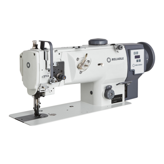
- Page 1 4220SW INDUSTRIAL SEWING MACHINE INSTRUCTION MANUAL www.reliablecorporation.com...
-
Page 2: Table Of Contents
CONTENT OPERATION INSTRUCTION 1. Brief introduction 1.5. Main specifications Installing the oil pot Lubrication Installing the needle Loading the bobbin in the bobbin case Removing and installing the bobbin case Adjusting the bobbin winder attention assembly Winding the bobbin thread Threading Adjusting the stitch length Adjusting the thread tension nut... - Page 3 INSTRUCTION MANUAL...
-
Page 4: Brief Introduction
1.5. Main specifications 1. Brief introduction This machine is suitable for sewing the heavy Application Medium and heavy duty materials of car seats, sofas, tarpaulins, tents, bags, etc. Max. sewing 1800 s.p.m max speed Max. stitch speed Needle bar 36mm stroke DP*17 (Nm125-Nm180) Needle... -
Page 5: Installing The Oil Pot
2. Installing the oil pot (Fig. 2) an oil pan 1.Install the bolt ①, oil seal ② and spacer ③ onto the oil reservoir, and then put the cushion ⑤ and spacer ⑧ into the set screw ④, then set it by nut ⑥. -
Page 6: Installing The Needle
4. Installing the needle (Fig. 4) 1.Turn the balance wheel to raise the needle bar to its highest position; 2.Loosen the set screw and make the long face towards the left; groove of the needle 3.Insert the needle into the needle bar; 4.Tighten the set screw . -
Page 7: Removing And Installing The Bobbin Case
6. Removing and Installing the bobbin case (Fig. 6) 1.When removing the bobbin case from the hook ① assembly, lift the latch and pull the case straight out. 2. Align the bobbin case with the rotating hook shaft then insert it. Align the inside of the rotating hook ②... -
Page 8: Threading
9. Threading (Fig. 9) Thread in the order as shown in Fig. 9 10. Adjusting the stitch length (Fig. 10) 1. Turning the dial ① towards a larger number increases the stitch length and turning it towards a lower number decreases the stitch length. 2. -
Page 9: Adjusting The Thread Take-Up Spring
12. Adjusting the thread take-up spring (Fig. 12) 1.Changing the travel of the thread take-up spring: a.Loosen the set screw , move the stopper leftward and rightward, then adjust the thread take-up spring b.Move the stopper ③ rightward to increase the movement of the take-up spring and left to decrease it. -
Page 10: Adjusting The Height And Presser Foot Walk
16. Adjusting the height and pressure foot walk (Fig. 16) To adjust the height of the presser foot walk loosen nut ②, slide the lever up to increase the height of the walk or slide the lever down to decrease the height of the walk. -
Page 11: Parts Manual
PARTS MANUAL... -
Page 12: Arm And Bed
1. Arm and bed... - Page 13 1. Arm and bed No . Part Number Name Remark Face plate assembly Screw (1) Screw (2) Safety guard Screw Side cover(1) Seal spacer Screw Side cover(2) Screw Upper cover Screw Rubber plug Small cover Screw Upper thread guide plate Screw Upper thread guide Screw...
-
Page 14: Upper Shaft And Thread Take-Up Mechanism
2. Upper shaft and thread take-up mechanism... - Page 15 2. Upper shaft and thread take-up mechanism No . Part Number Name Remark Thread take-up lever pin shaft Screw Oil wick Thread take-up lever Slide block Oil wick Needle bar link Needle bar crank pin Oil wick Screw Needle bar crank Screw Screw Upper shaft...
-
Page 16: Needle Bar Vibrating Parts
3. Needle bar vibrating parts... - Page 17 3. Needle bar vibrating parts No . Part Number Name Remark Needle bar Needle bar thread guide Needle Screw Needle bar adapter Oil wick Screw Vibrating shaft Crank Crank pin Screw Oil felt Spring Slide block Vibrating shaft front bushing Vibrating shaft rear bushing Oil felt Needle bar vibrating frame...
-
Page 18: Upper Feed Parts
4. Upper feed parts... - Page 19 4. Upper feed parts No . Part Number Name Remark Dial Dial bushing Bushing Adjusting shaft Spring Screw Screw Upper feed shaft Upper feed crank Screw Upper feed shaft bushing(left) Screw Rubber plug Upper feed bushing(right) Oil felt Collar Screw Walking foot Screw Walking foot lifting bar...
- Page 20 4. Upper feed parts...
- Page 21 4. Upper feed parts No . Part Number Name Remark Presser bar guide plate Washer Screw (upper) Screw (lower) Pin shaft Adjusting bracket Screw shaft crank screw screw bushing shaft screw retaining plate screw connecting plate screw ring bracket screw crank screw link...
- Page 22 5. Feed parts...
- Page 23 5. Feed parts No . Part Number Name Remark Feed Link Oil Felt Link Pin Screw Reverse Feed Bracket Retaining Plate Screw Presser Plate Screw Reverse Feed Bracket Shaft Screw Slide Block Feed Vibrating Bar Assembly Oil Wick Screw Stitch Length Adjusting Dial Bolt Seal Ring Screw...
-
Page 24: Lower Shaft Mechanism
6. Lower shaft mechanism... - Page 25 6. Lower shaft mechanism No . Part Number Name Remark Hook CPL Bobbin case CPL Lower shaft Lower shaft synchronized pulley CPL Screw Lower shaft bushing (L) Lower shaft bushing (M) Lower shaft bushing (R ) Screw Lower shaft gear Screw Collar Screw...
- Page 26 7. Thread tension and bobbin thread winder mechanism...
- Page 27 7. Thread tension and bobbin thread winder mechanism No . Part Number Name Remark Thread tension plate assembly Bobbin thread tension assembly Screw Thread winder assembly Friction ring Screw Cutter Screw...
-
Page 28: Knee Lifter Mechanism
8. Knee lifter mechanism... - Page 29 8. Knee lifter mechanism No . Part Number Name Remark Knee control lever support Screw Knee control lever Screw Knee control connecting rod Screw Screw Crank Screw Knee control revolving shaft Spring Position block Screw Screw Screw Knee control bell bent bar Bell bracket Screw Knee control bell...
-
Page 30: Lubrication
9. Lubrication... - Page 31 9. Lubrication No . Part Number Name Remark Oil felt Oil felt support Screw Small oil felt Binding cord Oil wick Oil felt Press plate Screw Oil pot Oil pot cover Screw Oil felt Oil tube Oil wick Oil felt 1 Oil felt 2 Oil retaining plate Screw...
-
Page 32: Accessories
10. Accessories... - Page 33 10. Accessories No . Part Number Name Remark Spool stand Small oil pot Parts bag Spanner Spanner Bobbin Needle Screwdriver (medium) Screwdriver (small) Double ended spanner Screwdriver (big) Machine head cover Oil reservoir Screw Oil pot Adapter Seal ring Presser plate Connecting screw Spacer Seal spacer...
Need help?
Do you have a question about the 4220SW and is the answer not in the manual?
Questions and answers