Advertisement
and the K Design
KOBALT
®
trademarks of LF, LLC. All Rights Reserved.
ATTACH YOUR RECEIPT HERE
Serial Number
Questions, problems, missing parts? Before returning to your retailer, call our
customer service department at 1-888-3KOBALT (1-888-356-2258), 8 a.m. - 8 p.m., EST,
Monday - Friday.
AB13851
®
are registered
Purchase Date
1
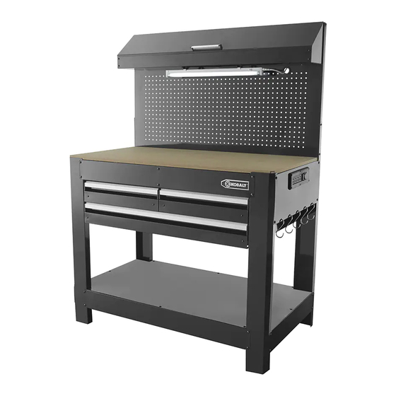
ITEM # 0484712
3 DRAWER
WORKBENCH
MODEL #3DPCWB2013
Français p. 16
Español p. 31
Advertisement
Table of Contents

Related Manuals for Kobalt 3DPCWB2013


Summary of Contents for Kobalt 3DPCWB2013
- Page 1 ITEM # 0484712 3 DRAWER WORKBENCH MODEL #3DPCWB2013 Français p. 16 and the K Design KOBALT ® ® are registered Español p. 31 trademarks of LF, LLC. All Rights Reserved. ATTACH YOUR RECEIPT HERE Serial Number Purchase Date Questions, problems, missing parts? Before returning to your retailer, call our customer service department at 1-888-3KOBALT (1-888-356-2258), 8 a.m.
-
Page 2: Table Of Contents
TABLE OF CONTENTS Package Contents ............. . 3 Hardware Contents . -
Page 3: Package Contents
PACKAGE CONTENTS PART QUANTITY PART DESCRIPTION QUANTITY DESCRIPTION Drawer back (small) Rear leg (left) Drawer bottom panel (large) Front leg (left) Drawer back (large) Side panel (left) Drawer front (large) Side frames (left & right) Storage cage side panel (left) Rear leg (right) Hinge (left) Front leg (right) -
Page 4: Hardware Contents
HARDWARE CONTENTS M6x10 mm Screw M4x6 mm Screw M4x8 mm Screw M6x10 mm Screw Qty. 52 Qty. 44 Qty. 2 Qty. 12 SAFETY INFORMATION Please read and understand this entire manual before attempting to assemble, operate or install the product. DANGER: ELECTRICAL SHOCK HAZARD. -
Page 5: Assembly Instructions
ASSEMBLY INSTRUCTIONS Important: Do not over-tighten the screws as this may result in stripping them. After the workbench is completely assembled, fully tighten each screw. 1. Attach the left rear leg (1L) and the left front leg (2L) to the side frame (4) using screws (AA). On the side frame (4), ensure the edge with the hole is facing up. - Page 6 ASSEMBLY INSTRUCTIONS 3. Align the left drawer slide panel (8L) with the pre- drilled holes, ensuring the slides are toward the front of the unit. Attach using screws (EE). Hardware Used M6x10 mm Screw Repeat steps 1 through 3 for the right legs (5R and 6R), right side panel (7) and drawer slide panel right (9R).
- Page 7 ASSEMBLY INSTRUCTIONS 6. Attach a bottom frame (11) to the front of the left and right rear legs (1L and 5R) using screws (AA). Ensure the holes on the bottom frame (11) are facing up. Hardware Used M6x10 mm Screw 7.
- Page 8 ASSEMBLY INSTRUCTIONS 9. Loosely attach screws (AA) to the end of the intermediate slide support (10). Align the screws (AA) with the holes in the back panel (14), insert the screws (AA) into the holes and lower the intermediate slide support (10). Tighten the screws (AA). Hardware Used M6x10 mm Screw...
- Page 9 ASSEMBLY INSTRUCTIONS 12. Attach the small drawer front (18) to the left drawer side panel (15L) and right drawer side panel (16R) by inserting screws (BB) through the small drawer front (18) and into the side panels (15L and 16R). Insert (DD) screws through parts (15L and 16R) and into sides of drawer front (18).
- Page 10 ASSEMBLY INSTRUCTIONS 15. Extend the slides located on the drawer slide panels (8L and 9R) to their full extension over the drawer rails. Align the drawer with the extended slides. Insert the extended slides into the slide supports on both sides of the drawer.
- Page 11 ASSEMBLY INSTRUCTIONS 18. Secure the left and right storage cage side panels (23L and 26R) with screws (AA and BB). Hardware Used M6x10 mm Screw M4x6 mm Screw 19.Align the storage cage lid (25) with the storage cage lid drawer pull (34). Secure using the screws (DD). Hardware Used M3.2x6 mm Screw...
- Page 12 ASSEMBLY INSTRUCTIONS 21. Attach the pegboard (28) to the left rear leg (1L) and the right rear leg (5R) using screws (AA). Hardware Used M6x10 mm Screw 22. Attach the light support brackets (29) to the underside of the storage cage bottom panel (27) using screws (CC) packaged with the light support bracket (29).
- Page 13 ASSEMBLY INSTRUCTIONS 23. Place the wooden table top (32) onto the workbench above the drawers. 24. Insert the hanging hooks (33) into the holes on the right side of the workbench. DRAWER REMOVAL 1. Pull the drawer out of the workbench until the slides are fully extended.
-
Page 14: Care And Maintenance
CARE AND MAINTENANCE Cleaning 1. Clean using a mild liquid soap, rinse with clean water and dry thoroughly. Do not clean with abrasive detergents. 2. Clean off water or other liquids spilled or splashed on the workbench immediately and dry the unit thoroughly. -
Page 15: Year Limited Warranty
3-YEAR LIMITED WARRANTY This item carries a 3-year warranty from the date of purchase against defective parts and workmanship. Warranty does not cover damage due to mishandling or abuse. This warranty gives you specific legal rights, and you may have other rights that vary from state to state. REPLACEMENT PARTS LIST PART PART ID...
Need help?
Do you have a question about the 3DPCWB2013 and is the answer not in the manual?
Questions and answers