Endress+Hauser iTEMP TMT71 Brief Operating Instructions
Temperature transmitter
Hide thumbs
Also See for iTEMP TMT71:
- Operating instructions manual (100 pages) ,
- Brief operating instructions (28 pages) ,
- Safety instructions (24 pages)
Table of Contents
Advertisement
Quick Links
KA01414T/09/EN/02.19
71442342
2019-05-29
Products
Brief Operating Instructions
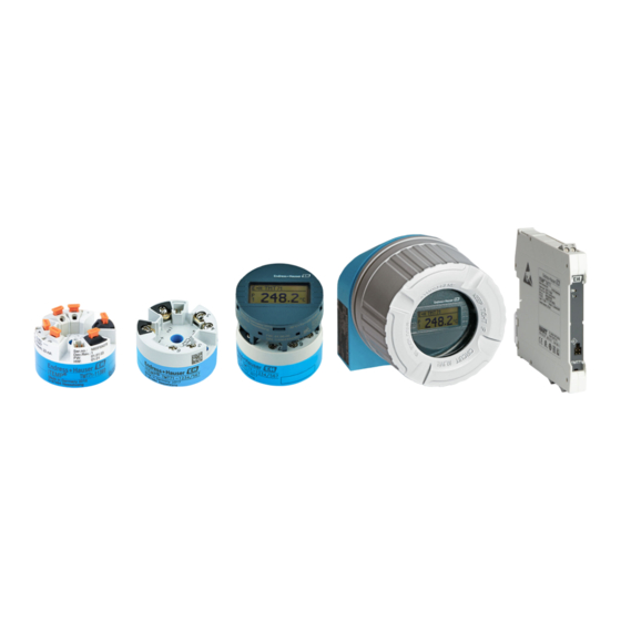
iTEMP TMT71, TMT72
Temperature transmitter
TMT71 with 4 to 20 mA analog output
TMT72 with HART® communication
These Instructions are Brief Operating Instructions; they are
not a substitute for the Operating Instructions pertaining to
the device.
For detailed information, refer to the Operating Instructions
and other documentation.
Available for all device versions via:
• Internet: www.endress.com/deviceviewer
• Smart phone/Tablet: Endress+Hauser Operations App
Solutions
Services
Advertisement
Table of Contents

Related Manuals for Endress+Hauser iTEMP TMT71


Summary of Contents for Endress+Hauser iTEMP TMT71
- Page 1 These Instructions are Brief Operating Instructions; they are not a substitute for the Operating Instructions pertaining to the device. For detailed information, refer to the Operating Instructions and other documentation. Available for all device versions via: • Internet: www.endress.com/deviceviewer • Smart phone/Tablet: Endress+Hauser Operations App...
- Page 2 TMT71, TMT72 Order code: XXXXX-XXXXXX Ser. no.: XXXXXXXXXXXX Ext. ord. cd.: XXX.XXXX.XX Serial number www.endress.com/deviceviewer Endress+Hauser Operations App A0023555 Endress+Hauser...
-
Page 3: Table Of Contents
TMT71, TMT72 Table of contents Table of contents About this document ............. . 3 Safety Instructions (XA) . -
Page 4: Symbols Used
About this document iTEMP TMT71, TMT72 on the nameplate. If the two numbers (on the Ex documentation and the nameplate) are identical, then you may use this Ex-specific documentation. Symbols used 1.2.1 Safety symbols Symbol Meaning DANGER! This symbol alerts you to a dangerous situation. Failure to avoid this situation will result in DANGER serious or fatal injury. -
Page 5: Tool Symbols
TMT71, TMT72 About this document 1.2.3 Symbols for certain types of information Symbol Meaning Symbol Meaning Permitted Preferred Procedures, processes or actions that Procedures, processes or actions that are permitted. are preferred. Forbidden Procedures, processes or actions that Indicates additional information. -
Page 6: Basic Safety Instructions
Basic safety instructions iTEMP TMT71, TMT72 Basic safety instructions Requirements for the personnel The personnel for installation, commissioning, diagnostics and maintenance must fulfill the following requirements: ‣ Trained, qualified specialists must have a relevant qualification for this specific function and task ‣... -
Page 7: Incoming Acceptance And Product Identification
TMT71, TMT72 Incoming acceptance and product identification Electromagnetic compatibility The measuring system complies with the general safety requirements as per EN 61010-1, the EMC requirements as per the IEC/EN 61326 series and the NAMUR recommendations NE 21. NOTICE ‣... -
Page 8: Product Identification
(www.endress.com/deviceviewer): All data relating to the device and an overview of the Technical Documentation supplied with the device are displayed. • Enter the serial number on the nameplate into the Endress+Hauser Operations App or scan the 2-D matrix code (QR code) on the nameplate with the Endress+Hauser Operations App: all the information about the device and the technical documentation pertaining to the device is displayed. - Page 9 TMT71, TMT72 Incoming acceptance and product identification Input: 11-42V Ser.no.: 012345678910 Dev.Rev: x Ext. ord. cd.: XXXXXXXXXXXXX# xx.yy.zz TMT82- XXXXX/XX iTEMP 12345678ABCDEFGH Made in Germany 201x 12345678ABCDEFGH D-87484 Nesselwang A0014561 1 Nameplate of the head transmitter (example, Ex version)
-
Page 10: Scope Of Delivery
Incoming acceptance and product identification iTEMP TMT71, TMT72 3.2.2 Name and address of manufacturer Name of manufacturer: Endress+Hauser Wetzer GmbH + Co. KG Address of manufacturer: Obere Wank 1, D-87484 Nesselwang oder www.endress.com Address of manufacturing plant: See nameplate Scope of delivery The scope of delivery of the device comprises: •... -
Page 11: Installation
TMT71, TMT72 Installation Installation Installation conditions 4.1.1 Dimensions 5 (0.2) A0036303 3 Head transmitter version with screw terminals. Dimensions in mm (in) Spring travel L ≥ 5 mm (not for US - M4 securing screws) Mounting elements for attachable measured value display Interface for contacting measured value display The same dimensions apply to the version with push-in terminals. - Page 12 Installation iTEMP TMT71, TMT72 12.5 (0.49) 116 (4.57) A0039296 The height of housing H varies depending on the terminal version: screw terminals = 114 mm (4.49 in), push-in terminals = 111.5 mm (4.39 in) 4.1.2 Mounting location • Head transmitter: •...
-
Page 13: Installation
TMT71, TMT72 Installation 4.1.3 Important ambient conditions • Ambient temperature: –40 to +85 °C (–40 to 185 °F), . • Head transmitter in accordance with climate class C1, DIN rail transmitter in accordance with B2 as per EN 60654-1 •... - Page 14 Installation iTEMP TMT71, TMT72 4.2.1 Mounting the head transmitter Item A Item B . 7 2 i n ) Item C . 7 2 i n ) A0039675-EN 4 Head transmitter mounting (three versions) Procedure for mounting in a terminal head, Fig. A: Open the terminal head cover (8) on the terminal head.
- Page 15 TMT71, TMT72 Installation . 5 1 i n ) 6.5 mm . 8 3 i n ) (0.25 in) . 7 2 i n ) A0024604 5 Dimensions of angle bracket for wall mount (complete wall mounting set available as accessory) Procedure for mounting in a field housing, Fig.
- Page 16 Installation iTEMP TMT71, TMT72 Mounting typical of North America A0008520 6 Head transmitter mounting Thermometer design with thermocouples or RTD sensors and head transmitter: Fit the thermowell (1) on the process pipe or the container wall. Secure the thermowell according to the instructions before the process pressure is applied.
-
Page 17: Post-Installation Check
TMT71, TMT72 Installation 4.2.2 Mounting the DIN rail transmitter NOTICE Wrong orientation Measurement deviates from the maximum accuracy rating when a thermocouple is connected and the internal reference junction is used. ‣ Mount the device vertically and ensure it is oriented correctly! A0039678 ... -
Page 18: Electrical Connection
Electrical connection iTEMP TMT71, TMT72 Electrical connection CAUTION ‣ Switch off the power supply before installing or connecting the device. Failure to observe this may result in the destruction of parts of the electronics. ‣ Do not occupy the display connection. An incorrect connection can destroy the electronics. -
Page 19: Quick Wiring Guide
TMT71, TMT72 Electrical connection Quick wiring guide Sensor input RTD, Ω 4-, 3- and 2-wire TC, mV Supply voltage/ bus connection white white Display connection/ CDI interface A0038010-EN 8 Terminal assignment of head transmitter Supply voltage 4...20 mA Sensor input RTD, Ω... -
Page 20: Connecting The Sensor Cables
Electrical connection iTEMP TMT71, TMT72 NOTICE ‣ ESD - electrostatic discharge. Protect the terminals from electrostatic discharge. Failure to observe this may result in the destruction or malfunction of parts of the electronics. Connecting the sensor cables 5.3.1 Connecting to push-in terminals A0039468 ... -
Page 21: Connecting The Transmitter
TMT71, TMT72 Electrical connection Fig. C, Releasing the connection: Press down on the lever opener. Remove the wire from the terminal. Release lever opener. Connecting the transmitter Cable specification • A normal device cable suffices if only the analog signal is used. - Page 22 Electrical connection iTEMP TMT71, TMT72 2- 1+ 2- 1+ A0039698 11 Connecting the signal cables and power supply Head transmitter installed in field housing Head transmitter installed in terminal head DIN rail transmitter mounted on DIN rail Terminals for HART ®...
-
Page 23: Special Connection Instructions
TMT71, TMT72 Electrical connection A0037914 12 Fitting the CDI connector of the configuration kit for configuration, visualization and maintenance of the head transmitter via PC and configuration software Configuration kit, e.g. TXU10 with USB connection CDI connector Installed head transmitter with CDI interface... -
Page 24: Post-Connection Check
Electrical connection iTEMP TMT71, TMT72 A0014463 13 Shielding and grounding the signal cable at one end with HART ® communication Optional grounding of the field device, isolated from cable shielding Grounding of the cable shield at one end Supply unit ®... -
Page 25: Operation Options
TMT71, TMT72 Operation options Operation options Overview of operation options SmartBlue FieldCare TMT72 RN221N HART® Modem A0036305 14 Operation options for the transmitter via HART® communication SmartBlue FieldCare TMT71/ Configuration TMT72 RN221N A0037893 15 Operation options for the transmitter via the CDI interface The transmitter' s optional Bluetooth interface is only active if a display unit is not attached or the CDI interface is not used for device configuration. - Page 26 Operation options iTEMP TMT71, TMT72 6.1.1 Measured value display and operating elements Option: Display TID10 for head transmitter The display may also be subsequently ordered at any time after purchasing the transmitter, see the ' A ccessories' section in the Operating Instructions for the device.
- Page 27 TMT71, TMT72 Operation options Item no. Function Description ' C onfiguration locked' symbol The ' c onfiguration locked' symbol appears when configuration is locked via the hardware. Status signals DIN rail transmitter Two LEDs on the front indicate the device status.
-
Page 28: Transmitter Configuration
The display can be rotated 180° using the "DISPL. 180°" DIP switch. Transmitter configuration ® The transmitter and measured value display are configured via the HART protocol or CDI (= Endress+Hauser Common Data Interface). The following operating tools are available for this purpose: Operating tools FieldCare, DeviceCare, Field Xpert SIMATIC PDM... -
Page 29: Commissioning
TMT71, TMT72 Commissioning A0037924 System requirements • Devices with iOS: • iPhone 4S or higher, from iOS9.0 • iPad2 or higher, from iOS9.0 • iPod Touch 5th generation or higher, from iOS9.0 • Devices with Android: Android 4.4 KitKat or higher Download the SmartBlue app: Install and start the SmartBlue app. -
Page 30: Switching On The Transmitter
Commissioning iTEMP TMT71, TMT72 Switching on the transmitter Once you have completed the post-connection checks, switch on the supply voltage. The transmitter performs a number of internal test functions after power-up. During this process, a sequence containing device information appears on the display. - Page 32 www.addresses.endress.com...
Need help?
Do you have a question about the iTEMP TMT71 and is the answer not in the manual?
Questions and answers