Table of Contents
Advertisement
Quick Links
Other products from Martindale:
G 16th Edition Testers
G All-in-one's
G Calibration Equipment
G Continuity Testers
G Electrician's Kits
G Full Calibration & Repair Service
G Fuse Finders
G Digital Clamp Meters
G Digital Multimeters
G Microwave Leakage Detectors
G Motor Maintenance Equipment
Martindale Electric Company Limited
CABLE JOINTS, CABLE TERMINATIONS, CABLE GLANDS, CABLE CLEATS
FEEDER PILLARS, FUSE LINKS, ARC FLASH, CABLE ROLLERS, CUT-OUTS
Metrohm House, Penfold Trading Estate, Imperial Way, Watford, WD24 4YY, UK.
Tel: +44(0)1923 441717 Fax: +44 (0)1923 446900
E-mail: sales@martindale-electric.co.uk
Website: www.martindale-electric.co.uk
© Martindale Electric Company Ltd. 2006
Registered in England No. 3387451. Rev 1
G Non-trip Loop Testers
G PAT Testers & accessories
G Phase Rotation Units
G Proving Units
G Socket Testers
G Thermometers & Probes
G Test Leads
G Voltage Indicators
G Specialist Metrohm Testers (4 & 5kV)
G Specialist Drummond Testers
11KV 33KV CABLE JOINTS & CABLE TERMINATIONS
FURSE EARTHING
www.cablejoints.co.uk
Thorne and Derrick UK
Tel 0044 191 490 1547 Fax 0044 191 477 5371
Tel 0044 117 977 4647 Fax 0044 117 9775582
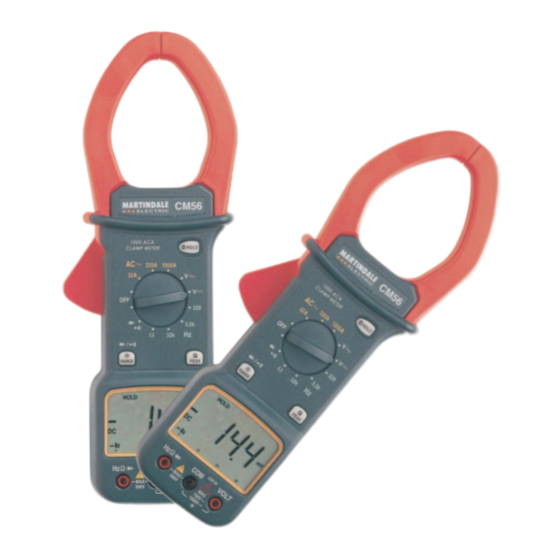
CM56
CLAMP METER
I
NSTRUCTION
M
ANUAL
MARTINDALE
E L E C T R I C
Trusted by professionals
Advertisement
Table of Contents

Related Manuals for T&D CM56


Summary of Contents for T&D CM56
- Page 1 Other products from Martindale: G 16th Edition Testers G Non-trip Loop Testers CM56 CLAMP METER G All-in-one’s G PAT Testers & accessories G Calibration Equipment G Phase Rotation Units G Continuity Testers G Proving Units G Electrician’s Kits G Socket Testers NSTRUCTION G Full Calibration &...
- Page 2 Particular attention should be paid to these warnings, the precautions, the technical specifications and the use of the CM56 in dry surroundings. Always inspect your clampmeter, test leads and accessories for any sign of damage before use.
-
Page 3: Table Of Contents
CONTENTS Introduction Description Unpacking & Inspection Replacing the Battery Safety Information Operation Voltage Measurement Current Measurement Resistance Measurement Continuity Testing Diode Testing Frequency Measurements Maintenance Cleaning Repair & Service Storage Conditions Warranty Technical Specifications... -
Page 4: Introduction
1. INTRODUCTION This manual contains information and warnings which must be followed to ensure safe operation of the clampmeter. WARNING READ "SAFETY INFORMATION" BEFORE USING THE METER This clampmeter is a handheld 3200-count instrument that is designed for use in the laboratory, field servicing and any circumstance where high current measurement is required. - Page 5 1. Volt - Input Terminal This is the positive input terminal for VOLT measurements. Connection is made to it using the red test lead. 2. COM - Common Terminal This is the negative (Ground) input terminal for all measurement modes except current.
-
Page 6: Unpacking & Inspection
9. Clamp Jaws AC Volts (Average sensing RMS indicating) Frequency Response: 50Hz to 300Hz Detect AC current flowing through the conductor on test. Range Resolution Accuracy Input Impedance 10. Trigger Press the lever to open the clamp jaws. When the lever is released, the jaws will 3.2V ±(1.5% rdg+4d) 11MΩ... -
Page 7: Safety Information
This meter is powered by a NEDA type 1604 or equivalent 9-volt battery. When * Accuracy is given as ± ([% of reading]+[number of least significant digits]) at the meter shows the " " the battery must be replaced to maintain correct 18°C to 28°C with relative humidity up to 70%. -
Page 8: Operation
3. OPERATION Specification WARNING CM56 Clamp Meter To avoid possible electric shock, instrument damage and / or equip- ment damage, do not attempt to take any voltage measurements if the voltage is above 1000V DC or 750VAC. These are the maximum voltages that this instrument is designed to measure. -
Page 9: Current Measurement
4.1 Cleaning The CM56 may be cleaned using a soft dry cloth. Do not use abrasives, The clamp jaws are overload protected up to 500VAC for up to 1 minute. solvents, or detergents, which can be conductive. Allow to dry completely Do not take current readings on circuits where the maximum current before using. -
Page 10: Continuity Testing
3.4 CONTINUITY TESTING 3.3 RESISTANCE MEASUREMENTS 1. Select the ( ) position by turning the rotary selector switch and WARNING press the "range" button to enter continuity testing. Attempting resistance or continuity measurements on live circuits can 2. Follow steps 2 & 4 as for resistance measurements cause electrical shock, damage to the instrument and damage to the equipment under test.
Need help?
Do you have a question about the CM56 and is the answer not in the manual?
Questions and answers