Table of Contents
Advertisement
Quick Links
Advertisement
Table of Contents

Related Manuals for T&D VR-71


Summary of Contents for T&D VR-71
- Page 1 User’s Manual Thank you for purchasing our product. Carefully read this instruction manual before using this unit. Distributed by MicroDAQ.com, Ltd. www.MicroDAQ.com (603) 746-5524 © Copyright T&D Corporation. All rights reserved. 2013.04 16504220004 4th Edition...
- Page 2 Distributed by MicroDAQ.com, Ltd. www.MicroDAQ.com (603) 746-5524...
-
Page 3: Table Of Contents
Contents Notices about this User’s Manual -------- 2 Viewing Current Data --------------------- 40 Software User’s Agreement --------------- 3 Saving Recorded Data -------------------- 41 Safety Precautions and Instructions ---- 4 Creating Text File --------------------------- 42 What is Voltage Recorder? ---------------- 8 Opening a Opening a Saved File ------ 43 Package Contents ------------------------- 10 Part Names and Functions -------------- 11... -
Page 4: Notices About This User's Manual
Notices about this User’s Manual In order to properly use this product, please carefully read this manual before using. T&D Corporation accepts no responsibility for any malfunction of and/or trouble with this product or with your computer that is caused by the improper handling of this product and will deem such trouble or malfunction as falling outside the conditions for free repair outlined in the attached warranty. -
Page 5: Software User's Agreement
Software User’s Agreement Escape Clauses T&D Corporation does not guarantee the operation of "Voltage Recorder for Windows". T&D Corporation shall not accept any responsibility for any damage, whether direct or indirect, that results from the usage of "Voltage Recorder for Windows". Specifications of "Voltage Recorder for Windows"... -
Page 6: Safety Precautions And Instructions
Safety Precautions and Instructions Please carefully observe the following safety measures when using our product. To prevent any loss or damage to our customers, other people and / or property, and to ensure the proper use of our products we ask that before using our product you carefully read, understand and follow the safety rules and precautions for our products as outlined below. - Page 7 DANGER While installing and using this product, make sure to always follow your com- puter manufacturer's warnings and cautions. Do not take apart, repair or modify the main unit. It may cause fire, electrocu- tion or damage. Ask the shop where you purchased the product or T&D Cor- poration to carry out any repairs.
- Page 8 If the unit gets dirty, wipe it with a clean cloth and a mild detergent. The VR-71 uses a common ground for both channels, so when connecting input cables be sure to connect the ground (black wire) for each channel to the same.
- Page 9 Remove batteries from any unit that will not be used for a long period of time. Batteries left in a unit not being used for a long time may leak and cause a malfunction. To prevent damage to the unit from static electricity, remove static electricity from your body by touching metal around you (door knob, window frame) before touching the unit.
-
Page 10: What Is Voltage Recorder
The expansion unit (optional) allows you to transmit a preheat signal that is synchronized with the VR-71 recording timing to turn sensors or other devices ON and OFF, and also allows you to simultaneously record with up to 4 VR-71 units. - Page 11 LCD as the unit of measurement. Current Data Display By communicating at a 1 second interval with a VR-71 logger connected to your computer it is possible to view the current data readings in real time graph form.
-
Page 12: Package Contents
Package Contents The following items are included in the package: Voltage Recorder VR-71 Input Cable VR-7101 x 2 Voltage Recorder for Windows® AAA Alkaline Battery x 2 Software (CD-ROM) x 1 User’s Manual (Warranty) x 1 Serial Communication Cable x 1 Distributed by MicroDAQ.com, Ltd. -
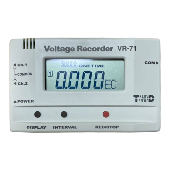
Page 13: Part Names And Functions
Part Names and Functions Appearance Diagram Front LCD Display DISPLAY INTERVAL REC/STOP Button Button Button Side Channel 1 Communication Input Cable Jack Cable Jack Channel 2 Power Switch Back Battery Case Button Operations DISPLAY Button : Press to switch to View Ch 1 only / View Ch 2 only/ View both channels alternately / View neither channel. - Page 14 LCD Display Channel Mark The channel number of the measurement being displayed will appear. REC Mark The recording status is displayed. ) : Recording in progress, BLINKING( ) : Waiting for programmed start. Recording Capacity After every 2000 readings the scale will be marked from left to right. Display Status If Endless...
- Page 15 Other Displays During the communication of settings or during the download of data the (COM) mark will appear in the space where read- ings usually appear. FULL When recording under the One Time mode and upon reach- ing capacity of 8,000 readings, “FULL” will appear in the LCD display and recording will automatically stop.
-
Page 16: Installing The Batteries
Installing the Batteries Remove the battery cover form the back of the unit. Insert 2 AAA alkaline batteries, making sure that the + and - are in the correct direction. Always use new batteries. Replace and close the battery cover. Changing the Batteries When battery power becomes low, a battery life warning signal will appear in the unit’s LCD display. -
Page 17: Connecting The Input Cable
<Main Unit> NOTE: The VR-71 uses a common ground for both channels, so when connecting input cables be sure to connect the ground (black wire) for each channel to the same point. A circuit to prevent shorts is included, but if you connect to different points it may cause damage to the logger or to the origin of the signal. -
Page 18: Turning The Power On
Turning the Power On Turn on the power by pushing up the power switch on the logger. Due to the back-up function, even if the power is turned OFF, data will not be lost. If you are in the process of measuring or recording, the measuring or recording will be stopped. -
Page 19: Installation
Installation Before installing, confirm the following Is Windows operating properly? If Windows is not operating properly, “ Voltage Recorder for Windows ” may not be installed correctly or it may not operate properly. Please quit all other applications If other programs are open, please close and quit all of them, making sure to quit all Quick Start programs such as a virus checker. -
Page 20: Software Operation
Software Operation How to Open Open "Voltage Recorder for Windows" from the Windows Start Menu or Start Screen. For details about how to use the software, please see the explanations in the Software Help Menu. In the Menu Bar, click [Help] - [Search by Topic] , then click on one of the tabs [Contents], [Index], or [Search] to search for the topic or term you are unsure about or have questions about. - Page 21 In the Menu Bar, click [Help] - [Data Display Format Settings], then select date display format. By clicking the help button in a dialog box, an explanation for that dialog box will appear. In the Graph Window, by clicking on the in the toolbar, you can have short explanations appear the next time you click on a menu, an icon, or anything in the main window.
-
Page 22: Connecting The Data Logger
Connecting the Data Logger Connecting the Data Logger to your Computer Connect the serial communication cable to your computer Connect the serial (RS-232C) communication cable to your computer Make sure to connect it to the correct place to ensure communication. Make sure that the cable is inserted fully, so as not to cause an improper connection. -
Page 23: Setting Up The Com Port
Setting up the COM Port Make necessary serial port settings to enable communication via the serial communication cable. With Voltage Recorder for Windows set the serial port you wish to use. There are two ways to make the port settings: [Auto-Detect] or [Specify Settings]. Using [Auto-Detect] * Make sure that the data logger is connected by the serial cable to the serial port you wish to use. - Page 24 UsingSpecify Settings In the [Communication] Menu, select [Serial Port Settings]. In the [Possible COM Ports] List, place a check next to the port you wish to use for the Voltage Recorder for Windows. Click the [OK] button to finish the settings. Check the COM Port you wish to use.
-
Page 25: Recording Start
Recording Start There are 2 ways to start recording Start recording by using the computer software..Recording will start on the specified date and time. Start Recording via Buttons on Logger..By pressing the REC button on the logger recording will start immediately. * When using the Expansion Unit, see the user’s manual that accompanies the Expansion Unit. - Page 26 Immediate Start: Recording will begin upon the completion of the settings. Expansion Unit Preheat:Transmits a preheat signal that is synchronized with the VR-71 recording timing to turn sensors or other devices ON and OFF. Simultaneous Recording : allows you to simultaneously record with up to 4 VR-71 units.
-
Page 27: How To Start Recording Via Buttons On Logger
How to Start Recording via Buttons on Logger If you wish to make settings to the Channel Name, Recording Mode, Input Voltage Range, Scale Settings or any others, it must be done first from the computer using the software. Click the INTERVAL button to select the Recording Interval By pressing in on the REC button for more than 2 seconds the REC mark will appear in the LCD and recording will start. -
Page 28: Scale Settings
Scale Settings Here is where you can make settings for the desired scale from the voltage readings and the unit display pattern for the logger LCD. Scale Settings Logger LCD Display Pattern Editing Area. The unit for display in the Graph Scale Settings Specify how you wish the values for the recorded data for each channel’s input voltage range to... -
Page 29: Creating Measuring Unit Patterns For Logger Display
Creating Measuring Unit Patterns for Logger Display Creating a Dot Pattern There are 2 ways to create dot patterns. Click the and select, or enter a new one directly. By clicking the [Display Pattern] button, the dot pattern editing area will appear. - Page 30 [Read Settings] [Save Settings] Button Button Read Settings Read the settings by calling up the scale settings file in which they have been saved. Save Settings t is possible to assign a name and save all scale settings, including logger LCD patterns, in the Scale Settings File.
-
Page 31: Downloading Data
Downloading Data Connect the data logger to your computer. For details about connecting the data logger, see [Connecting the Data Logger] on page 12. In the [Communication] Menu, select [Download Recorded Data]. If you are recording by msec, you cannot download data while recording. Please stop recording first and then download data. -
Page 32: Graph Display Names And Functions
Graph Display Names and Functions A and B Cursor Movement Buttons By clicking the arrow buttons, you can simultaneously move the A/B cursors. A and B Cursor Buttons Click and drag the A or B button to move the cursor to the left or right. The Vertical Axis Display ON/OFF Shift the vertical axis scale display ON/OFF. - Page 33 By dragging the gauge you can move left and right to the data you want to be displayed. Vertical Axis of Each Channel The vertical axis scale is displayed for each channel. By clicking , the axis can be scrolled for each channel. Button for Moving Vertical Axis The vertical axis moves up or down by clicking these arrow buttons.
- Page 34 Data List Display: [View] Menu This is a list of the data that was displayed in graph form. [Date / Time] Button y clicking this button, you can shift the display between the recorded date and the amount of elapsed time since recording started.
-
Page 35: Graph Maintenance
Graph Maintenance Making Changes to the Graph Display Selected Channels ON / OFF: [View] Menu By moving the mouse to [Selected Channels ON / OFF], the channel numbers are displayed. By clicking the channel No. of the channel you wish to view, the settings will be completed. * The same operation can be done by clicking on the channel number icons in the Toolbar. - Page 36 Re-order Channel Data: [Tools] Menu You can re-order the data during graph display. There are two methods to use when re-ordering channels:[Re-order by Dragging a Channel Number] and [Specify the Channel Numbers to be Moved]. Re-order by Dragging a Channel Number Drag the channel name / number you wish to move to the newly desired channel name / number position and drop it.
- Page 37 Set High, Low, Average Calculation Range: [Tools] Menu Enter the new calculation range in the [Set High, Low, Avg. Calculation Range] [OK] button [Entire Graph] Enter the button numerical values By clicking the [Entire Graph] button, the dates and times for the entire graph will be displayed. If in the graph display, you place the A cursor at the position for the beginning of the calculation range and the B cursor at the end of the range, those dates and times will appear as the new range in the [Set High, Low, Average Calculation Range] Display when it is opened.
- Page 38 Scale / Unit Conversion: [Tools] Menu It is possible to make settings for the conversion of units and scales for each channel of downloaded data. Select to use 2 voltage points to convert the scale or to use the conversion equation of y=Ax+B.
- Page 39 Change Graph Colors: [Tools] Menu Click the topic you wish to change. If you wish to change the colors: By clicking the button the color samples will appear. If you wish to change the line widths: Each click of the button will make the lines wider and each click of the button will make them thinner.
- Page 40 Vertical Axis Range Display Settings: [Tools] Menu You can set the upper and the lower limits of the graph's vertical axis scale for each channel. NOTE: If you have put a check on [Fixed], the lines in the graph may exceed the boundaries of the graph.Set the lower limit at more than –40,000 and set the upper limit at less than 40,000.
-
Page 41: Graph Graph Graph Operations: [Graph] Menu
Graph Operations: [Graph] Menu Return to Original Size Return from zooming in on one part of data to the original whole graph size. Zoom out step by step Return step-by step from zooming in on one part of data to show a larger range of data. Distributed by MicroDAQ.com, Ltd. -
Page 42: Viewing Current Data
Viewing Current Data By communicating at a 1 second interval with a VR-71 logger connected to your computer it is possible to view the current data readings in real time graph form. NOTE: It is impossible to save the data displayed in the current data readings. -
Page 43: Saving Recorded Data
Saving Recorded Data After downloading recorded data, please save any necessary data. Three Ways to Save Files In the [File] Menu, [Overwrite All Data] Will save any changes to file without changing File Name and Saving Location.The same operation can be carried out from [Save] in the Toolbar. In the [File] Menu, select [Save All Data as...] Save with a new File Name. -
Page 44: Creating Text File
Creating Text File By saving the recorded data as text file, you can create a file type that can be read by common spreadsheet software. Click [Save Data in Text File] in the [File] Menu. Select the [Text File Type] and [Range to be saved], and click [OK]. Comma, Tab, Space, and Semi-colon are codes used by common spreadsheet software, such as Excel and Lotus, when reading Text File to divide cells. -
Page 45: Opening A Opening A Saved File
Opening a Opening a Saved File To open a previously saved file, designate the file name to open it. Click [Open] in the [File] Menu. Select the name of the data you wish to open and click [Open] to view the data in graph form. Select a File [Open] button... -
Page 46: Troubleshooting
Troubleshooting I can not communicate with my computer using serial (RS-232C) communication, what should I do? Please confirm the following items. Check the Main Unit • Check to make sure that there is enough battery power and that the power of the main unit is ON. - Page 47 * How to check your Communication Port? In the Device Manager it is possible to check whether the communication port is usable or not. If Usable: If Not Usable: An "!", an "x" or an "arrow" will appear If you are using a USB-Serial Adaptor: If Usable: If Not Usable: Under "Other Devices"...
- Page 48 If an "!", an "x" or an "arrow" appears, the port is not usable. To find out details about any communication port with an "!", an "x" or an "arrow" mark, right click on the port and select [Properties]. Q:I can’t get the communication cable connected to the computer. What should I do? A: Please connect the communication cable provided with the Voltage Logger into the serial port of your computer (D-SUB 9 pin male connector).
-
Page 49: Specifications
Specifications Voltage Recorder VR-71 Measurement Item Voltage Number of Channels 2 (Common ground) Measurement Range Range:±1,2,6,15V Auto Range:Fixed Range Measurement Accuracy ±0.5%±5dgt [10°C~ 30°C] Display Resolution Min 1mV Recording Interval 20 selections : 0.02sec - 60min (Default : 10seconds) Recording Capacity... -
Page 50: Options
Options Unit:mm VR-7101 Input Cable Cable Length : about 1m VR-7102 Input Cable Cable Length : about 1m VR-7103 4-20mA Probe Maximum Current Input : 40mA Internal Resistance : 100 Output : 2V at 20mA / 0.4V at 4mA Conversion Accuracy : 0.5% Cable Length : about 1m Clip M3.5 Crimp Terminal Vinyl Coated Electrical Wire Stereo Mini Jack ( 2.5) VR-00P1 Expansion Unit... - Page 51 For product information or questions contact us at Shimadachi 817-1, Matsumoto, Nagano 390-0852 Japan T E L : + 81 - 263-40-0131 F A X :+81 - 263-40-3152 Office Hours : Monday to Friday 9:00 - 12:00 / 13:00 - 17:00 (GMT + 9:00 Tokyo Time) T&D Website ht tp://www.