Table of Contents
Advertisement
Quick Links
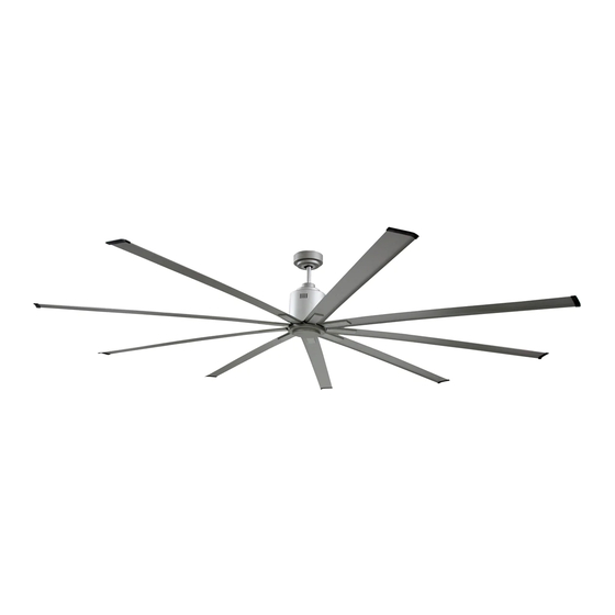
DC CEILING FAN
MODELS ICF72, ICF88, ICF96
-
INSTALLATION
-
OPERATION
-
MAINTENANCE
-
WARRANTY INFORMATION
Need more help with your install?
Scan the QR code at left to watch our installation
video, or visit the video directly by typing in the
following link into your browser:
https://youtu.be/b55PHe3E3rw
Or call our Customer Service Line at 1-800-433-1626
READ INSTRUCTIONS CAREFULLY FOR SAFE
READ AND SAVE THESE INSTRUCTIONS FOR
INSTALLATION AND FAN OPERATION.
SAFE INSTALLATION AND OPERATION.
CAUTION
CAUTION
Made in Taiwan.
Advertisement
Table of Contents

Subscribe to Our Youtube Channel
Related Manuals for Maxx air ICF72


Summary of Contents for Maxx air ICF72
- Page 1 DC CEILING FAN MODELS ICF72, ICF88, ICF96 Made in Taiwan. INSTALLATION OPERATION MAINTENANCE WARRANTY INFORMATION Need more help with your install? Scan the QR code at left to watch our installation video, or visit the video directly by typing in the following link into your browser: https://youtu.be/b55PHe3E3rw...
-
Page 2: Congratulations On Your Purchase
CONGRATULATIONS ON YOUR PURCHASE Congratulations on purchasing the latest in energy saving ceiling fans. This fan runs on DC (direct current) power which gives it the benefit of being super energy efficient whilst still maintaining high volume air-movement and silent operation. Energy Saving –... -
Page 3: Before Installation
BEFORE INSTALLATION Unpack your fan and check contents. You should have the following: Fig. 1 Mounting bracket x 1 Extra motor screws with spring washers x 7 1/4”-20 x 5/16” (not shown) Fan assembly with hanger cover, Blade screws with washers x 28 #10-24 x 1/4”... -
Page 4: Installing The Fan
INSTALLING THE FAN TOOLS REQUIRED: Phillips / flat head screwdriver Pair of pliers Adjustable spanner Step ladder Wire cutter Wiring, supply cable as required by local provincial and national wiring codes and regulations. INSTALLING THE MOUNTING BRACKET The ceiling fan must be installed in a location so that the blades are 1 ft. spacing from the tip of the blade to the nearest objects or walls. - Page 5 DOWNROD AND HANGER ASSEMBLY • Prior to assembly slide hanger cover (1A) and canopy cover (3A) onto downrod (2A). Hanger cover will be facing ceiling to cup over mounting bracket and canopy cover will face down to cover motor screws. Down Rod 2A Canopy Cover 3A Hanger Cover 1A...
- Page 6 • Adjust the safety cable to the desired length. It is recommended to attach a safety cable near the mounting bracket to a secure mounting point to allow the hanger cover to cover the safety cable as well as the hanger. Photo 5: Safety cable attached near hanger Photo 6:...
- Page 7 Mounting Bracket Stopper of bracket Notch of ball joint Fig. 4 Fig. 5 PREPARE AND COMPLETE THE ELECTRICAL WIRING — WIRING DIAGRAM (FIG. 6) WARNING: FOR YOUR SAFETY ALL ELECTRICAL CONNECTIONS MUST BE UNDERTAKEN BY A LICENSED ELECTRICIAN. NOTE: AN ADDITIONAL ISOLATING WALL SWITCH MUST BE INCLUDED IN THE FIXED WIRING. NOTE: IF THERE ARE TWO OR MORE DC CEILING FANS INSTALLED IN THE ONE LOCATION, AN ISOLATION SWITCH IS REQUIRED FOR EACH CEILING FAN.
- Page 8 INSTALL CANOPY COVER • Loosen 2 screws from the bottom of the mounting bracket. • Slide the canopy up to the mounting bracket and place the key hole on the canopy over the screw on the mounting bracket, turn canopy until it locks in place at the narrow section of the key holes, secure it by tightening the two set screws.
-
Page 9: Using Your Ceiling Fan
Fig. 11 Fig. 10 USING YOUR CEILING FAN Pairing Transmitter and Receiver – when 2 or more DC ceiling fans are installed in one location When two or more fans are located near each other, you may want to have the receiver/transmitter for each fan set to a different code, so that the operation of one fan does not affect the operation of the other fans. - Page 10 • Press and hold the SET button of transmitter 1 for 6 seconds within 60 seconds of switching the power to the receiver of ceiling fan 1. • Now the transmitter should be paired with the receiver of ceiling fan 1. Turn ON/OFF or change the speed of ceiling fan 1 by the transmitter to check the operation.
- Page 11 tes t 5-10 SECONDS IS REQUIRED TO ALLOW THE DC FAN TO RESPOND TO THE REMOTE’S SPEEDS OR FAN DIRECTION SELECTIONS, AS DC FANS INCORPORATE A SENSOR CONTROL WHICH CONTROLS THE POWER TO THE MOTOR. ○ 2 - FAN OFF BUTTON: Press the button to turn the fan off.
- Page 12 tes t Turn off the main power supply to the receiver for more than 30 seconds and turn on the main supply to receiver again. Press and hold the SET button on the remote for 6 seconds within 60 seconds of turning the power on to the receiver.
- Page 13 tes t Please repeat the (A)-(C) steps to check the function. If the issues still persist after following point (A) to (D) and there is still no control, then please contact the local retailer for a new remote or transmitter. NOTE: For your safety, a new receiver must be installed by a licensed electrician.
- Page 14 tes t FAN CARE AND WARRANTY INFORMATION • Periodic cleaning of your ceiling fan is the only maintenance required. Use a soft brush or lint free cloth to avoid scratching the paint/plated finish. Please make sure the fan is not operating when cleaning. •...
-
Page 15: Troubleshooting Checklist
tes t TROUBLESHOOTING CHECKLIST Always check the “Troubleshooting Checklist” included in this booklet before calling for service. For your safety, ensure the ceiling fan is OFF before carrying out any troubleshooting. TROUBLE PROBABLE CAUSES SUGGESTED REMEDY Check main and branch circuit fuses or circuit A. -
Page 16: Technical Information
TECHNICAL INFORMATION DC FAN models Rated Voltage Rated power (motor) Battery for remote ICF72 – 72 in. ceiling fan 110VAC 1 x 12V 23AE ICF88 – 88 in. ceiling fan 110VAC 1 x 12V 23AE ICF96 – 96 in. ceiling fan...
Need help?
Do you have a question about the ICF72 and is the answer not in the manual?
Questions and answers