
Related Manuals for Centroid M Series


Summary of Contents for Centroid M Series
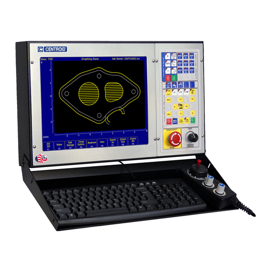
- Page 1 CENTROID ™ M-SERIES Operator's Manual Version 8.21 Rev. 030826 U.S. Patent #6490500 © 2003 Centroid Corp. Howard, PA 16841...
- Page 3 CNC Control Information Sheet Fill out the following and fax back to Centroid Tech support 814-353-9265. Date: _________ Company name: _________________________ Your name: ____________________________ Address: ______________________________ City: _________________ State:____ Zip: ________ Phone #: ________________ Fax #: __________________ Control Serial Number K_________ Software Version: _______ Approx. purchase date: __________...
- Page 4 Control Parameters Please fill in the parameter tables below. To get to the parameter screens: 1. Go to the Main screen of CNC7 software (this is the screen that appears when your system is first turned on). 2. Press <F1> to enter the Setup screen. 3.
-
Page 5: Table Of Contents
TABLE OF CONTENTS CHAPTER 1 - Introduction CHAPTER 9 - Engraving Window Description Quick Start Engraving Software Tutorial Conventions Machine Home CHAPTER 10 - Intercon Software Keyboard Operation Intercon Main Screen 10-1 Insert Operation 10-8 CHAPTER 2 - CNC7 Main Screen Graphics 10-42 Option Descriptions... -
Page 7: Chapter 1 - Introduction
CHAPTER 1 Introduction Window Description The CNC7 display screen is separated into five areas called windows. A sample screen is shown below for reference. The five windows are the DRO display window, the status window, the message window, the options window, and the user window. - Page 8 Status window The first line in the status window contains the name of the currently loaded job file. Below the job name are the Tool Number, Program Number, Feedrate Override, Spindle Speed, and Feed Hold indicators. The Feedrate Override indicator displays the current override percentage set on the Jog Panel. If your machine is equipped with a variable frequency spindle drive (inverter), the Spindle indicator will display the current spindle speed.
-
Page 9: Conventions
Conventions *Keystrokes are represented by enclosing the capitalized name of the key in "less than" and "greater than" symbols. For example, the A key is written as <A> and the enter key is written as <ENTER>. The "Escape" key is written as <ESC>. -
Page 10: Machine Home
Machine Home When the M-Series control is first started, the Main screen will appear as below. Before you can run any jobs, you must set the machine home position. If your machine has home/limit switches, reference marks or safe hard stops, the control can automatically home itself. If your machine has reference marks, jog the machine until the reference marks are lined up, (see below), before you press CYCLE START to begin the automatic homing sequence. -
Page 11: Keyboard Operation
Keyboard Operation A computer style keyboard is supplied with most systems. This keyboard can be used as a jog panel. See Chapter 14, “Operator Panels” for more information. The keyboard jog panel has many “hot keys”. Hot keys are keys that can be used at almost any time, with few exceptions. - Page 12 Mill M and G Codes This is a summary list of M and G codes. See Chapters 12 – 13 for more information. Stop for operator Rapid Positioning Optional Stop for operator Linear Interpolation Restart Program Circular or Helical Interpolation CW Spindle on CW Circular or Helical Interpolation CCW Spindle on CCW...
-
Page 13: Chapter 2 - Cnc7 Main Screen
CHAPTER 2 CNC7 Main Screen Option Descriptions F1 – Setup This will bring up the Setup menu as shown below. F1 - Part This key displays the Part Setup menus which are explained in Chapter 3. F2 - Tool This key displays the Tool Setup menus which are explained in Chapter 4. F3 - Config This key displays the Configuration menu which is explained in Chapter 15. - Page 14 F2 – Load Job This option allows you to specify the file name of the CNC program that you want to run next. On the Load Job screen, the available keys are: <F1> change to the Floppy drive (A:\ directory) <F2>...
- Page 15 CNC extension Using this ability is similar to using DIR and CD in DOS but leaving off the DIR or CD. If you can only remember part of the file name or it is located in another directory, these commands make it easier to locate. (See the DIR and CD commands in your PC-DOS manual for further information).
- Page 16 An extra option unique to the “Search and Run” screen is the <F1> “Do Last Tool Change” function. This key toggles the tool change option as shown on screen. A "YES" tells the control to perform a tool change so that the tool specified for the line or block has the tool indicated in the program.
- Page 17 F5 - CAM Choose <F5> from the Main Menu to load an installed CAM software package. Currently, the default CAM system is Intercon (Interactive Conversational) software. Your dealer can install other CAD/CAM packages. If more than one CAD/CAM program or on line software package has been installed, a menu will appear that allows you to choose the appropriate program.
-
Page 18: Canceling And Resuming Jobs
<F2> - Press this key to rotate your part. Use the keyboard arrow keys to rotate any direction. <F2> - Press this key to change the planar view of your part. The view is indicated by a TOP, RIGHT, or FRONT shown at the top of the screen. -
Page 19: Resuming A Canceled Job
EMERGENCY STOP (E-Stop) Pressing the EMERGENCY STOP key while a job is running will cause the control to abort the job currently being run. The control will stop movement immediately, clear all M-functions, and return to the main screen. Also, the power to all axes will be released. - Page 20 Pressing the <F1> key will display a complete list of editor functions and the key(s) that activate them. Press any key to return to editor screen. Editor Functions The following table contains a list of all available editor functions, the keys that activate them, and brief descriptions of their effects: Editor function Key(s)
- Page 21 See user dialog table below. Save current file to disk. Exit See user dialog table below. Quit using editor. See user dialog table below. Search forward Specify string to search for; this is Search forward again a case-sensitive search Replace Replace all occurrences of one text string with another string.
-
Page 23: Chapter 3 - Part Setup (F1 From Setup)
CHAPTER 3 Part Setup (F1 from Setup) General The Part Setup menu is used to set the part location or the coordinate system origin for the part. <F1> will display the position for the next axis. If changes were made to the current axis, but not yet accepted, they will be discarded. -
Page 24: Operation Description
For description of <F4> and <F5>, see Chapter 8. Operation Description Setting the part zeros establishes a coordinate system with an origin at the part zero. The <F1> Next Axis option selects the axis to be defined next. This field toggles between axis X, Y, Z and the fourth axis (if you have a 4-axis system). - Page 25 Example 1 (You are using the reference tool to find the Z-axis part zero): Set Tool Number to 0. Setting the Tool Number equal to zero tells the controller that you are using the reference tool. Example 2 (You are using a tool other than the reference tool, and not a ball nose cutter): Set Tool Number to the number this tool is assigned in the tool library.
-
Page 26: Part Setup Examples
Part Setup Examples Example 1: Setting the X-axis Part Zero with no offset (See diagram below) If you wanted the left edge of the part to be the origin for the X-axis: 1. Move the Edge Finder to the left edge of the part 2. -
Page 27: Work Coordinate Systems Configuration
Example 2: X-Axis origin offset into part 1 inch. If you wanted the origin offset 1 inch into the part: 1. Move the Edge Finder to the left edge of the part 2. Press <F1> until the axis field displays 'X' 3. - Page 28 When you enter the Work Coordinate System Configuration screen, the DRO display will automatically switch over to machine coordinates as an aid to entering numbers. All the values on this screen are represented in machine coordinates. F1 - Travel Limits and Reference Return Points The <F1>...
-
Page 29: Coordinate Systems Rotation
Coordinate System Rotation (CSR) Coordinate System Rotation saves you time when setting up your part. Rather than clamping your part and indicating the edge of the material to square it with the machine axes, you can use CSR to automatically rotate the coordinate system to the angle of the part or fixture that was probed. - Page 30 The instructions on how to perform a CSR measurement are numbered on the screen. Distance: The distance the X axis (in front or back orientation) or Y axis (in right or left side orientation) will move to probe the second point. If the distance is negative, the axis will be moved in the negative direction. Clearance Amount: The distance the Z axis will be moved upward when moving between the first probe point and the second probe point.
-
Page 31: Chapter 4 - Tool Setup (F2 From Setup)
CHAPTER 4 Tool Setup (F2 from Setup) Tool Setup allows you to specify information about the tools you will be using. Press <F1> to edit the Offset Library Height Offset and Diameter (H and D) values, or <F2> to edit the Tool Library tool descriptions. Offset Library The Offset Library file contains the values for the Height Offset and Diameter Numbers. - Page 32 To edit the Height Offset entries move to the desired height offset number with the arrow keys, <Page Up>, <Page Down>, <HOME>, and <END>. You can choose to manually edit or automatically measure the value. Height Offsets values are measured using the Z Reference position. The Z Reference position is the Z-axis position when the tip of the reference tool is touching the work surface.
-
Page 33: Automatic Tool Measurement
Automatic Tool Measurement Z-minus single-surface probing, using the TT-1 tool touch-off post, is available in the Tool Offset Library. NOTE: Make sure the proper parameters are set as per Chapter 8, and the detector is plugged in and is at the correct location on the table! WARNING: When first testing the TT-1, hold the TT-1 in hand and touch the unit off the tool to confirm correct setup. -
Page 34: Tool Library
1. Load the probe into the machine. 2. Jog the probe over the desired reference surface and press <F1>. 3. Press <F3> and then CYCLE START; the probe will find the Z Reference. At this point, the Z Reference is now entered into the Offset Library and is the reference height for all other tools. Remove the probe and measure any other tool offsets manually as described earlier in this chapter. - Page 35 Note: If enhanced ATC features are not on, the cursor cannot be moved into the bin column and the message “Bin fields are locked.” will appear where the tool in spindle display is located. In addition, the F1, F2, and F3 keys only appear if enhanced ATC features are on.
- Page 36 M-Series Operator’s Manual 10/29/03...
-
Page 37: Chapter 5 - Power Feed (F4 From Setup)
CHAPTER 5 Power Feed (F4 from Setup) The Power Feed screen is used to command axis movement. All the operations available on the Power Feed screen may also be performed in MDI with the appropriate M and G codes. F1 - Absolute Power Feed Press <F1>... - Page 38 M-Series Operator’s Manual 10/29/03...
-
Page 39: Chapter 6 - The Utility Menu
CHAPTER 6 The Utility Menu To get to the Utility Menu, press <F7> at the CNC7 Main Screen. The model number will vary depending on your M-Series Control model. F1 - Format Press <F1> to enter the Format Screen that gives you a choice of formatting either a high density or a low-density floppy disk. - Page 40 F2 - DD Pressing <F2> will perform the same function as above, except that the floppy disk will be formatted at double density (720K). F2 - Update To update your control software, put the update disk in the floppy disk drive and press <F2>. The new software will then be automatically loaded onto the hard drive.
-
Page 41: F4 - Restore
F4 - Restore Press <F4> to restore files that were previously saved with the Backup (<F3>) option. When restoring files be sure to have the proper back up disk. F1 - Config Press <F1> on this screen to restore the Controller's configuration from a floppy disk backup. F2 - CNC Press <F2>... - Page 42 F5 - File Ops Press <F5> to access an additional file options screen. These options operate on the CNC files stored on the Controller's hard drive. (The controller's CNC files are stored in the C:\CNC7\NCFILES directory.) F1 - Import Press <F1> to list files on the floppy drive. Make sure that the files on the floppy disk are CNC files. You can select the ones you want to import with <F1>...
- Page 43 CHAPTER 7 Digitize (F9 from Main Menu) The Digitize feature of CNC7 is used to digitize a rectangular surface area (grid), an inside circular bore area (radial), or a contour. The digitizing process creates a file with M & G codes that represent the digitized surface. If the digitizing probe tip is chosen to match the milling cutter size, the digitized file can be loaded and run to produce an exact copy of the digitized part.
-
Page 44: Grid Digitize
Grid Digitize (F1 from Digitize Screen) Grid Digitize Run Setup To set up a digitizing run, edit the parameters shown and then press CYCLE START. The control will move through the area to be digitized in a rectangular pattern. At each X-Y point in the pattern, it will measure the Z height of the sample surface, and record the coordinates in the data file. - Page 45 Z Maximum Depth: The maximum distance the Z-axis moves below the starting height. If the probe does not contact the surface at the maximum depth, that data point will be recorded as being at the maximum depth, and digitizing will proceed with the next point. Z Step Up: The distance the Z-axis moves up after making contact, before the control attempts to move X or Y.
- Page 46 Grid Digitize Notes 1. A guide to the possible grid digitizing paths is as follows: 2. A digitizing patch can be located anywhere in the coordinate system. The digitizing starting point is referenced from the part zero. For example, setting up digitizing, as shown in the figure on the right below, will record the first point at (X5, Y5, Z1) and the last point at (X7, Y7, Z1).
- Page 47 3. A good technique for calculating Z maximum depth is to touch off the lowest surface of the part to be digitized and set the part zero's Z value to Z0. Then jog the probe tip to a point higher than the highest surface of the part to be digitized.
-
Page 48: Radial Digitize
Digitizing the entire part and then adding multiple small patches along the walls can avoid vertical wall scalloping. A small rectangular patch extending the length of the vertical wall with the axis to move first set to the opposite axis along which the length of the wall extends is suggested (i.e. If a vertical wall extending along the X axis needs to be cleared of scallops, a small patch running the length of the wall with the Axis to Move First parameter set to Y would clear the scallops). - Page 49 Z Patch Depth: The depth of the patch to be digitized, along the Z-axis. A positive value will cause digitizing to proceed in the Z+ direction from the starting point; a negative value will cause digitizing to proceed in the Z- direction.
- Page 50 2. When radial digitizing, make sure the probe can fully retract to the center position without obstructions. Observe the two parts below. The cross section on the left has no obstructions that could keep the probe from full retraction to the center position. The cross section on the right does not allow the digitizing to retract to the center in Area A.
- Page 51 Partial Digitizing Sector Setup If you set the Radial Digitize Containment Angle to “Partial” then you must set up the Digitizing Setup by pressing <F2> from CNC7 Radial Digitize Screen. The partial sector can be by one of two methods: One method is by editing the start and end angles directly.
-
Page 52: Contour Digitize
Contour Digitize (F3 from CNC7 Digitize Screen) Contour Digitize Run Setup To set up a digitizing run, jog the probe tip to the center of the part and hit <F1> to assign that as your center point. Select CAM for a true CAM shape contour, or Wall for irregular shapes for wall following. Enter the rest of the parameters for the part and digitizing job as shown. - Page 53 Contour Digitize Parameters Copy Type: Toggle between CAM or Wall. Use CAM for precise replication of regular shapes and use Wall following for contours with irregular shapes. X Patch Length: The length of the contour to be digitized, along the X-axis. Y Patch Width: The width of the contour to be digitized, along the Y-axis.
- Page 54 Contour Digitize Notes Contour digitizing creates an M&G code file with a .CAM extension. The structure of the .CAM file starts with a header of comments indicating some of the parameters used when digitizing the contour, followed by the contour itself which is output as a subprogram.
-
Page 55: Chapter 8 - Probing
CHAPTER 8 Probing NOTE: Refer to the Probe Parameters section at the end of this chapter before using any probe. Part Setup with Probing Single axis, single surface probing is available on the Set Part 0/Position screen using the Auto (<F4>) key. This allows you to probe various surfaces to define the part coordinate system. -
Page 56: Calibrating The Probe Tip Diameter
1. Select the current work coordinate system by pressing <F6> or <F7>. Then select the axis you want to probe by pressing <F1>. <F1> , <F6> and <F7> are described in Chapter 4 (Part Setup). 2. Manually jog the probe about 1/2 inch away from the surface you wish to define. Make sure the approach direction to the part is set properly. - Page 57 The probing cycles will report the location and dimensions, as applicable, of the probed feature in a floating dialog box. The dimensions are adjusted to compensate for the probe tip diameter, entered in the Offset Library (see Parameter 12). For your convenience, you can edit the probe diameter on this screen, as long as the Tool Number, as set in Parameter 12, is not 0.
- Page 58 F3 - Slot Press <F3> to enter the Slot screen. A picture similar to the ones shown will appear along with instructions: 1. Press <F1> to select the orientation of the probe with respect to the Slot. 2. Slowly jog the probe to the approximate position shown in the picture. During this jog, make sure you have enough space between the probe and the part.
- Page 59 F5 - In Cnr (Inside Corner) Press <F5> to enter the Inside Corner screen. A picture similar to the following will appear, with instructions and an input field. The steps for this cycle are similar to that of a slot cycle. The main difference is that you need to enter a clearance amount.
-
Page 60: Probe Parameters
F7 - 1 Axis (Single Axis) Press <F7> to enter the Single Axis screen. Follow these steps: 1. Press <F1> to select the orientation of the probe. You will see one of the screens shown below. 2. Slowly jog the probe to the approximate position as shown in the picture. 3. -
Page 61: Chapter 9 - Engraving
Engraving Introduction Centroid offers an optional engraving package, which uses engraving software called Millwrite. Purchase of this option includes a user manual for the software. To launch the engraving software, press <F5> from the main screen, and select Millwrite from the options shown on the screen. - Page 62 Step 3: View the tool path Press <CTRL-V>. This will display the text in graphics mode. Press <ESC> and choose <Q>uit graphics. If you used the mouse go to B, otherwise press <ESC> then <ENTER> and type (without quotes) "V". Press <ENTER>. Step 4: Scale the symbol Drag the mouse to the right then to the bottom of the screen.
-
Page 63: Chapter 10 - Intercon Software
Intercon generates a G-code program from the geometric information you have entered. This is an advantage in several ways: 1. The G-code program generated by Intercon can be edited using the built-in Centroid G-code editor (<F6>) 2. Intercon programs can be interrupted and restarted even in the middle of a canned cycle. - Page 64 F1 - File Choosing <F1> File will display the screen below. Intercon stores part designs in files identified with the extension .ICN. For example, if you specify the name of a given part design as E_Z_CAM, this part design will be saved on disk in a file called E_Z_CAM.ICN.
- Page 65 the characters appear in the “File to load:” prompt above the function keys. Different drives and directories can be accessed by typing in the path at the “File to load:” prompt, or by pressing <F10> or <ENTER> on a bracketed directory name.
- Page 66 F7 – Copy Menus… Choosing <F7> will display these options: <F1> Copy Menu - allows a range of operations to be copied. Specify the Start Block, End Block, and Destination in the prompts that appear in the Copy Menu. The range of operations is copied into a location that precedes the destination block.
- Page 67 Comment Generation: When this field is set to Enabled, Intercon will put a comment describing the operation type before each block. Disabling Comment Generation will make the CNC files generated by Intercon smaller. Clearance Amount: This is the distance that Intercon raises the Z-axis above the programmed surface height in pockets, facing and frame mills when traveling across the work piece.
-
Page 68: Insert Operation
Insert Operation When you press <F2> from the Edit Operation screen, or when you choose New Part from the Main Screen, you will see the Insert screen: The new operation will be inserted right before the currently highlighted one. The block number of the new operation is shown on the right side of the screen. - Page 69 End: When you first access the rapid traverse screen, the cursor will be highlighting the first field, End X. This is the X coordinate of where the cutter will be after the rapid traverse has been completed. Similarly, Y and Z represent the coordinates of the cutter after the rapid traverse is completed.
- Page 70 The numbers in the different fields on the screen correspond to the following Linear Mill example shown here graphically: End: When you first access the linear mill screen, the cursor will be highlighting the first field, End X. This is the X coordinate of where the cutter will be after the linear move has been completed.
- Page 71 F3 - Arc Mill If you press <F3> for ARC MILL from the Insert Operation screen, you will see the following screen: The numbers in the different fields on the screen correspond to the following Arc Mill example shown here graphically: Operation Type: There are four ways to specify your ARC: using an endpoint and a radius (EP&R), using a center point and an angle (CP&A), using a center point and an end point (CP&EP), or using a mid-point and an end point...
- Page 72 Angle: Number of degrees through which the cutter will travel. This value must lie between 0 and 360 degrees. You will be able to edit this field only if you are specifying a center point and angle (CP&A) arc. Radius: Distance from the center of the arc to its edge. This value must be greater than 0. You will only be able to edit this value if you are specifying an end point and radius (EP&R) arc.
- Page 73 Tool Number: Number of the tool (between 1 and 200) to use. Entering this value pulls the current settings for this tool from the CNC7 tool library. You may then edit the length offset, diameter offset and diameter values if you wish to redefine your tool.
- Page 74 F5 - Canned Cycles When you choose the Canned Cycle operation by pressing <F5>, the following screen appears: Canned Cycle Introduction #1: Using Pattern and Repeat (Drilling, boring, tapping) Selecting the Drill, Bore or Tap canned cycle will give you four choices, selecting <F1> Drill is shown below. Bore and Tap will have the same menu selections as drill except with Drill is replace with Bore or Tap: All canned cycle operations using the Drill BHC (Bolt Hole Circle) or Drill Array are identical to their equivalent using the <F1>...
- Page 75 The bolt hole circle and array patterns are explained graphically in the following figure: Canned Cycle Introduction #2: Linear Repetition Of Operations (Drilling, Boring, Tapping) If you want to perform one operation several times in a linear pattern, simply define Position X, Y or both as incremental values.
- Page 76 The numbers in the fields on the screen correspond to the following example, shown here graphically: Drilling (F1 in the Canned Cycle Menu: option #1) If you press <F1> (Drill) from the Canned Cycle Menu, you will gain access to three types of drilling operations: Drilling, Chip Breaking, and Deep Hole drilling.
- Page 77 The numbers in the fields on the screen correspond to the following example, shown here graphically: Where: Cycle Type: Selects one of three drilling operations: Drilling, Chip Breaking, or Deep Hole drilling. Press <F3> or <SPACE> to toggle between the three choices. Position: Specifies the X and Y coordinates where the drilling will take place.
- Page 78 The numbers in the fields on the screen correspond to the following example, shown here graphically: Where: Cycle Type: Selects one of three drilling operations: Drilling, Chip Breaking, or Deep Hole drilling. Press <F3> or <SPACE> to toggle between the three choices. Position: Specifies the X and Y coordinates where the drilling will take place.
- Page 79 'Rapid To' Depth: The depth (below the Clearance Height but above the Surface Height) to which the cutter rapid moves before beginning to drill the hole at the specified Plunge Rate. Depth: Total: Depth of hole (incremental) as measured from Surface Height. Depth: Increment: Depth of each individual peck.
- Page 80 The numbers in the fields on the screen correspond to the following example, shown here graphically: Where: Cycle Type: Selects one of three drilling operations: Drilling, Chip Breaking, or Deep Hole drilling. Press <F3> or <SPACE> to toggle between the three choices. Position: Specifies the X and Y coordinates where the drilling will take place.
- Page 81 The numbers in the fields on the screen correspond to the following example, shown here graphically: Where: Position: Specifies the X and Y coordinates where the boring will take place. If either the X or Y coordinate is an incremental value, you will have the option to bore multiple holes in a linear pattern. (See Canned Cycle Introduction #2) Surface Height: Absolute Z-axis position from where each incremental depth is measured.
- Page 82 Hole Depth: Depth of hole (incremental) as measured from Surface Height. Plunge Rate: Z-axis speed of descent during drilling. The plunge rate can be toggled to modal, fixed or slave, this is indicated by the symbol beside the plunge rate field. If the plunge rate is modal then it will have the “M”...
- Page 83 The numbers in the fields on the screen correspond to the following example, shown here graphically: Where: Tap Head Type: Without rigid tapping, this selects either Floating tap head or Reversing tap head. If rigid tapping is enabled, you can select either rigid or reversing. Spindle Direction: Shows the current spindle direction.
- Page 84 Spindle Speed: Rate at which the spindle rotates. Used in conjunction with the Threads / Unit to calculate the plunge rate. * WARNING: The spindle speed must be set before performing this operation. Dwell Time: Delay at bottom of hole before starting ascent. This is used for a floating tap to allow the spindle time to reverse direction at the bottom of the hole.
- Page 85 The parameters in the previous screen correspond to the following dimensions: Start: X and Y coordinates of the starting corner of the area to be faced. Surface Height: Z coordinate of the top of the area to be faced. Length: X-axis dimension of the area to be faced. If a negative value is entered for the length, the facing will occur in the negative X-axis direction from the X-axis start position;...
- Page 86 The parameters on the screen correspond to the following dimensions: Where: Center: X and Y coordinates of the center of the RECTANGULAR POCKET. Surface Height: Z-axis position from which each incremental depth is measured. Length: X-axis dimension of the rectangular pocket. Width: Y-axis dimension of the rectangular pocket.
- Page 87 Depth: Plunge Type: Straight or Ramped. Straight plunge does a vertical Z plunge with no X, Y movement. Ramped plunge does a zigzag plunge limited by the Plunge Angle entered below. Depth: Plunge Angle: The maximum limit angle allowed for a ramped plunge. A special value of 0 means that there is no limit angle.
- Page 88 Where: Center: X and Y coordinates of the center of the circular POCKET. Surface Height: Z-axis position from which each incremental depth is measured. Diameter: Diameter of circular pocket. Cleanout: If cleanout is Yes, all the material in the pocket will be removed. If cleanout is No, a circular frame mill will result, with the cutter starting in the pocket center and arcing its way out and then going around the frame.
- Page 89 The parameters on the screen correspond to the following dimensions (rectangular frame): Where: Frame Type: Selects Inside Rectangle, Outside Rectangle, Inside Circle, and Outside Circle. Press <F3> or <SPACE> to toggle between them. Center: X and Y coordinates of the center of the frame mill. Surface Height: Z-axis position from where each incremental depth is measured.
- Page 90 Diameter: Diameter of the frame mill. (Circular frame only.) Corner Radius: Radius of curvature of the corners. On an Inside frame, corner radius must be greater than the current cutter radius. (Rectangular frame only.) Depth: Total: Total depth of the frame mill. Depth: Per Pass: Depth of each individual pass.
- Page 91 The parameters on the screen correspond to the following: Where: Center: X and Y coordinates of the center of the thread mill operation. Diameter: Major diameter of thread for external thread milling and minor diameter for internal thread milling. Thread / Unit: Number of threads per inch or mm. Used to calculate thread pitch. Thread Pitch: Thread pitch calculated from threads/unit field.
- Page 92 Cleanout (F9 in the Canned Cycle Menu) The cleanout cycle performs a horizontal zigzag pocket cleanout of a profile composed of lines and arcs. When you press <F9> (Cleanout) from the canned cycle menu, the following screen is displayed: Where: Rough Cuts: Selects type of rough cut: conventional or climb.
- Page 93 Depth: per Pass: The depth amount of cut to be taken to reach the total depth. This value must be greater than 0.0 and cannot exceed the total depth. Depth: Plunge Rate: The feedrate at which the Z axis is moved when plunging to a lower depth. After the cleanout parameters are accepted, the a screen similar to the following appears: To complete the contour to be cleaned out, choose <F2>...
- Page 94 F6 - Other Press <F6> to add a comment to your program, control flood, mist, spindle, and clamp; you can also send the tool to Z home or enter in any G code or M function available on your control. Pressing <F6> from the Insert Operation screen shows: Press <F1>...
- Page 95 This operation lets you directly enter M & G codes into your Intercon part program. Great care must be taken when using this function, as you could cause unpredictable results in the controller if you accidentally changed positioning modes in your program, or perhaps turned the spindle off during a cut. Rotary - Rapid Move If you have a fourth axis and it is rotary, then the OTHER screen will allow you to make rotary moves by pressing <F7>.
- Page 96 You can press <F3> or <SPACE> to select cutter compensation Left, Right, or Off. Cutter compensation may be used with Linear Mill, Frame Mill, and Rapid Traverse operations. For details on using cutter compensation, see Chapter 2 of the M-Series operator's manual. The Rectangular Pocket, Circular Pocket, and Frame Mill canned cycles perform cutter compensation automatically.
- Page 97 All subprogram operations contain the following fields: Start Block: Selects the first operation in the block of operations to repeat. This operation must lie before the place in your program where you are trying to repeat operations. End Block: Selects the last operation in the block of operations to repeat. Again, this operation must lie prior to place in your program where you are trying to repeat operations, but not precede the start block.
- Page 98 Repeat to Depth (F1 in the Insert Subprogram Menu) The Repeat to Depth feature is useful for repeating a part contour when the material being machined is too thick to cut in just one pass. The contour formed by these operations may either be a closed contour or an open one. If a non-vertical plunge to the start of the contour is desired, it must be programmed into the contour (a vertical plunge between passes will be provided if one is not programmed).
- Page 99 Increment: Specifies the X and Y distances between the start points of each copy of the contour. Number of Copies: The number of times to repeat the contour. Skip Copy: Prompt at which the list of skips may be modified. Entering positive integers adds skips to the list, while entering negative integers removes skips from the list.
- Page 100 Mirror Line: Specifies the type of mirror line to use. Choices are Horizontal, Vertical and Other (user-defined). X Offset: Specifies the X coordinate of a point on the Mirror Line. This field will not be visible if a horizontal mirror line is being defined. Y Offset: Specifies the Y coordinate of a point on the Mirror Line.
- Page 101 Skip Copy: Prompt at which the list of skips may be modified. Entering positive integers add skips to the list, while entering negative integers remove skips from the list. Multiple entries can be processed at the same time by separating them with commas. Skip List: List of skipped copies currently selected.
-
Page 102: Graphics
Graphics Intercon features three-dimensional previews of the tool path to be followed when milling the part. You may choose to display your project in one of two formats: a three-plane display, where the project is shown in each of the XY-, ZX-, and YZ-planes; an isometric display, which depicts the project three-dimensionally from an observer's point of view. - Page 103 F1 – 2D/3D Pressing <F1> selects the format of the project display. This may take the form of the three-plane display (2 - D) or the isometric display (3 - D). Three-plane (2D) Isometric (3D) F2 – View/Rotate In three-plane (2D) view, <F2> switches the point of view to a different plane. In isometric.(3D) view, <F2> enables the arrow keys to rotate the figure.
-
Page 104: Math Help
Math Help Intercon provides a math assistance function to solve the trigonometric problems common in part drawings. To enter Math Help, press <F6> from any Edit Operation screen. The first time that you invoke Math Help, the following screen appears which shows all available solvers: The figures on the right are a graphical representation of the highlighted solver on the left. - Page 105 F1 – Prev Soln F2 – Next Soln The Prev Soln and Next Soln options will cycle backward and forward, respectively, through the available solution sets for math solvers that may have multiple solutions. A status line near the bottom left of the screen appears once a valid solution has been found.
- Page 106 Other features common to all math help operations In some math help operations, there will be an asterisk ‘*’ character that appears immediately to the right of a field. This character marks the field as a “given” field, which means that the value of this field will be held constant in the process of solving the math equations.
- Page 107 F3 – Tangent: Line Arc Given the center (C1) and radius of an arc and 1 point (LP) on a line, find the lines tangent to the arc (defined by the tangent point (T1)). You must enter the X and Y coordinates for the circle's center point, the circle's radius, and the X and Y coordinates for a point on the line.
- Page 108 F5 – Tangent: Line Arc Arc Given the center points (CP1 and CP2) and radii (R1 and R2) of two arcs, find the lines (defined by T1 - T8) tangent to both arcs. You must enter the X and Y coordinates for the first circle's center point, the radius of the first circle, the X and Y coordinates for the second circle's center point, and the second circle's radius.
- Page 109 Given the center points (C1 and C2) and radii of two arcs and the radius of a third arc, find the center point of the third arc and the tangent points (T1 and T2). You must enter the radius of the tangent arc, the X and Y coordinates for the first circle's center point, the radius of the first circle, the X and Y coordinates for the second circle's center point, and the second circle's radius.
- Page 110 Given the center (CP) and radius (R) of an arc, 1 point (LP1) and either a second point (LP2) or one coordinate (LP2 X or Y) and the angle from horizontal, find the intersection point(s) (I1 and I2). You must enter the X and Y coordinates for the circle's center point, the circle's radius, the X and Y coordinates for one point on the line, and one of the following: * the X and Y coordinates of a second point on the line * the X coordinate of a second point and the angle from horizontal...
- Page 111 Given the center points (CP1 and CP2) and the radii (R1 and R2) of two arcs, find the intersection point(s) (I1 and I2) of the arcs. You must enter the X and Y coordinates for the first circle's center point, the radius of the first circle, the X and Y coordinates for the second circle's center point, and the second circle's radius.
-
Page 112: Intercon Tutorial #1
Intercon Tutorial #1 This is a step-by-step instructional example of going from blueprint to part with Intercon. The tool path to be created is for the part shown in Figure 1. For instructional purposes, this part will be programmed to cut into stock held in 3 fixtures, 6 inches apart along the X-axis. - Page 113 Part Creation Each feature of the part will become an operation in your program. Before beginning, decide where you want the X0 and Y0 reference. For this particular part, the center of the bolt hole pattern was selected. Now start the Intercon program (from the CNC7 Main screen, press <F5>...
- Page 114 N0030 Circular pocket Center: : 0.0000 : 0.0000 Surface Height : 0.0000 Diameter : 1.0000 Cleanout : Yes Depth: Total : 0.5000 Per Pass : 0.2500 Plunge Rate : 2.0000 Plunge Type : Ramped Plunge Angle : 0.00° Rough Cuts : Conventional Stepover : 0.2250...
- Page 115 FIG. 2 - Graphics screen showing bolt holes and circular pocket ESC/CANCEL Cancel Return to the editing screen. Accept Keep selected values. Cycles Access the list of available Canned Cycles. Frame Now add an outside frame to cut the flange out of the material. The flange is 3.0000 inches long by 3.0000 inches wide, and has rounded corners with 0.2500-inch radii.
- Page 116 FIG. 3 - Graphics screen showing part with bolt holes and outer frame ESC/CANCEL Cancel Return to the editing screen. Accept Keep selected values. Subpgm Access the Insert Subprogram screen. Repeat We programmed the part to cut one copy only. We now want to repeat the part 2 more times at an incremental distance of 6 inches along the X-axis.
- Page 117 If you do not wish to do this, press <ESC/CANCEL>. ESC/CANCEL Cancel Creation of the part is complete. Intercon programs automatically turn the spindle and coolant off at the end. File Press <F3> to save the part under its current name. Press <F4>...
- Page 118 Milling The Part Now that the part has been programmed, it is time to mill it. Take your material and clamp it to the table. Remember that the clamps must be positioned such that they do not interfere with the tool as it cuts. You may choose either to place the clamps around the edges of the material for the entire process and let the part drop through upon completion, or you may wish to pause after milling the circular pockets and place clamps through the holes to prevent the part from moving.
- Page 119 Tools Now you need to make sure that each tool uses the correct diameter and height offset values. Inspect the values for T001 and T002. T1 should use H001 and D001, while T002 should use H002 and D002. If any of these values are incorrect, use the arrow keys to select the incorrect values.
-
Page 120: Intercon Tutorial #2
Intercon Tutorial #2 This demonstration will show you how to create a tool path for a part from a blueprint using the Math Help function of Intercon. The tool path to be created is for the part shown in Figure 1 below. 4.0000"... - Page 121 PRESS ACTION COMMENTS Create a new program by filling in the appropriate program name (we recommend C_ROD) and your name. Press Enter or <F10> to accept the new name. Enter “Intercon Tutorial #2” for the description. Press <F10> to accept. Tool (M6) Describe the tool below.
- Page 122 FIG. 2 - Bolt Hole Circle N0030 Drill bolt holes Cycle Type : Drilling Center: : 0.0000 : 0.0000 Surface Height : 0.0000 Clearance Height : 0.5000 'Rapid To' Depth : 0.1000 Depth: Total : 0.5100 Plunge Rate : 2.0000[M] Dwell Time : 0.0000 Number of holes...
- Page 123 N0040 Tool change Tool Number Description : Tool #2 H002 D002 Position: X : 0.0000 Y : 0.0000 Tool H Offset (Tool Height : your tool) Tool D Offset Tool Diameter : 0.2500 Spindle Speed : 1000 Spindle Direction : CW (M3) Coolant Type : Flood (M8)
- Page 124 N0060 Circular pocket Center: : 4.0000 : 0.0000 Surface Height : 0.0000 Diameter : 0.7500 Cleanout : Yes Depth: Total : 0.5100 INC Per Pass : 0.2500 Plunge Rate : 2.0000 Plunge Type : Ramped ° Plunge Angle : 0.00 Rough Cuts : Conventional Stepover...
- Page 125 N0080 Rectangular pocket Center: X : 3.0000 Y : 0.0000 Surface Height : 0.0000 Length (X) : 0.7500 Width (Y) : 0.4250 Corner Radius : 0.1875 Depth: Total : 0.2500 Per Pass : 0.2500 Plunge Rate : 2.0000 Plunge Type : Ramped °...
- Page 126 N0110 Arc Arc Type: : EP&R X : 4.625 Y : 0.0000 Z : -0.0500 Center: Angle Radius : .5 Plane : XY Direction : CCW Connect Radius : 0.0000 Feedrate : 10.0000 Angle <= 180 You will see that after you enter in these values, the other points and arcs will be entered in automatically.
- Page 127 N0120 Arc Arc type : EP&R End: X : 4.6250 Y : 0.0000 Z : -0.0500 Center: Angle Radius : .625 Plane : XY Direction : CW Connect Radius : 0.0000 Feedrate : 10.0000 Angle <= 180° : Yes Math Help We are trying to find end points for the arcs that make up the outside edge of the part.
- Page 128 FIG. 4 - Screen showing Math Help Arc Tangent Arc solutions ARROWS Move Cursor If necessary, move the block cursor to the Tangent 1 X field as shown above. Note: Use only <↑> and <↓>. If you press the right arrow, press the left arrow to get back to the Math Help fields.
- Page 129 Arc type : EP&R X : 3.7746 Y : -0.5829 Z : -0.0500 Center: Angle Radius : 0.6250 Plane : XY Direction : CW Feedrate : 10.0000 Angle <= 180° : Yes Hide Math Hide Math Help temporarily. (We will return later to pick up the other tangent points.) Graph Observe Figure 5.
- Page 130 Accept Keep selected values. The other arc values were calculated for you. Arc (G2 & G3) The next arc to be cut is labeled as ARC 2 in Figure 3. The start point is labeled P2, the end point of the last arc. N0130 Arc ↑↓(UP/DOWN) Move Cursor...
- Page 131 ↑↓(UP/DOWN) Move Cursor Move down to the radius field and enter the radius of the arc labeled ARC 2 in Figure 3 (this radius is 3.1500 inches). Set the direction to “CCW”. Arc type : EP&R End: X : 0.7496 Y : -1.0003 Z : -0.0500 Center:...
- Page 132 FIG. 7 - Math Help solution for arcs 3 and 4. ↑↓( ARROWS) Move Cursor Press to highlight the needed tangent point X coordinate in Math Help. Tangent point T2 is the one you want this time. → (ARROW) Move Cursor Press to remove the graphic display and move the cursor to the arc operation.
- Page 133 Arc type : EP&R Mid: End: X : 0.7496 Y : 1.0003 Z : -0.0500 Center: Angle Radius : 1.2500 Plane : XY Direction : CW Feedrate : 10.0000 Angle <= 180° : No Accept Keep selected values. Arc (G2 & G3) The fourth arc to be cut is labeled as ARC 4 in Figure 3.
- Page 134 FIG. 8 - New arc 4 entry screen shown with solution for arcs 3 and 4 of Figure 3. ↑↓(UP/DOWN) Move Cursor Highlight the needed tangent point X. Tangent point T1 is the one you want this time. ARROWS Move Cursor If necessary, move the cursor to the arc operation and select the End X field.
- Page 135 N0160 Arc mill Operation type : EP&R Mid: End: X : 4.6250 Y : 0.0000 Z : -0.0500 Center: Angle Radius : 0.6250 Plane : XY Direction : CW Feedrate : 10.0000 Angle <= 180° : Yes Accept Keep selected values. Arc (G2 &...
- Page 136 DpthRpt We programmed the outer contour of the part so that our tool would only penetrate a small portion of the material per pass. We now want to repeat the outer contour operations until the tool has cut the entire way through the material (the assumed material thickness is 0.5 inches).
- Page 137 compensation is not represented except in pocket and frame displays). FIG. 9 - Draw screen showing complete part ESC/CANCEL Cancel Return to Main screen. File Go to the File Menu. Press <F3> to save under the current file name or press <F4> to save the program under a different name. Post The CNC file needed to run this part on your mill will be generated at this time.
- Page 138 As it processes each operation, it checks for values that, if used, will cause incorrect code to be produced. If such a value is found, a message will appear on the screen alerting you of the problem. For example, a problem with a rectangular pocket may produce this message: Changes to the part would then be required to allow proper code generation to proceed.
- Page 139 Milling The Part Now that the part has been programmed, it is time to mill it. Take your material and clamp it to the table. Remember that the clamps must be positioned such that they do not interfere with the tool as it cuts. You may choose either to place the clamps around the edges of the material for the entire process and let the part drop through upon completion, or you may wish to pause after milling the circular pockets and place clamps through the holes to prevent the part from moving.
- Page 140 NOTE: The tool heights used above are merely example heights. In order to accurately measure the heights of your tools, see the description of measuring tool heights on page 6 - 24 of this tutorial. Save Keep the updated tool offset library values. Tools Now you need to make sure that each tool uses the correct diameter and height offset values.
- Page 141 Measuring Tool Heights The following is a brief description of the method used to measure tool height values (offsets). You will need to insert a reference tool into the quill before beginning. PRESS ACTION COMMENTS Setup From the main screen enter the Setup. Tool Enter tool screen.
- Page 142 M-Series Operator’s Manual 10/29/03 10-80...
-
Page 143: Chapter 11 - Cnc Program Codes
Chapter 11 CNC Program Codes General The next three chapters contain a description of the CNC program codes and parameters supported by the M-Series Control. The M-Series Control has some G codes and parameters that are modal, and some that are "one shots." The G codes and parameters that are modal will stay in effect until a new G code or parameter is issued. - Page 144 H - Tool Length Offset Number H is used to select the Tool Length Offset Number. The H code offset amounts are stored in the file Offset Library. Tool Length Offsets can be specified anytime before a G43 or G44 is issued. Once specified the offset amount is stored and will only be changed when another H code is entered.
- Page 145 Q - Parameter Q is used as a depth parameter in canned drilling cycles. Example: G73 X1.5 Y2.0 Z-.75 R.25 Q.25 F5 ; Q Sets the depth cut at .25 R - Radius, Return Point, Parameter R can represent the radius, a return point, or a general parameter. This is used as a variable for any of those values in the NC file.
- Page 146 Example: : select absolute positioning : XY plane :Visible comments will be displayed on screen with the G-codes. ; - Internal Comment Identifier The semicolon (;) is used to indicate the start of an internal comment within a CNC program line. All characters after the semicolon are ignored when the program is run.
- Page 147 #, = - User or System Variable Assignment The ‘#’ character is used to reference a macro or a user or system variable. For variables that can be written, the ‘=’ is used to assign to them. Index Description Returns Macro arguments A-C Macro arguments I-K (1st set) Macro arguments D-F or 2nd set of I-K...
- Page 148 9000-9199 Parameter values 0 – 199 See Chapter 15. Index Description Returns 10000 Mill: Height offset amount, active H Floating point value 10001-10200 Mill: Height offset amount, H001 – H200 Floating point value 11000 Mill: Diameter offset amount, active D Floating point value 11001-11200 Mill: Diameter offset amount, D001 –...
- Page 149 Advanced Macro Statements (Optional) Warning: Branching and conditional execution are extremely powerful tools that, combined with access to system variables, allow you to do many things that would otherwise be impossible. Nevertheless, using branching and conditional execution can introduce undesirable and even unpredictable behavior into your programs.
- Page 150 Examples: ; Branch to N200 if machine position is okay, otherwise go to N300 N100 IF #5041 LE 5.0 THEN GOTO 200 ELSE GOTO 300 ; Force subprogram parameter #D to be within range. IF [#D LE 0.005] #[D] = 0.005 ;...
- Page 151 CHAPTER 12 CNC Program Codes: G-codes G-code Group Description Rapid Positioning Linear Interpolation Circular or Helical Interpolation CW Circular or Helical Interpolation CCW Dwell Exact Stop Parameter Setting Circular Interpolation Plane Selection XY Circular Interpolation Plane Selection ZX Circular Interpolation Plane Selection YZ Select Inch Units Select Metric Units Return to Reference Point...
-
Page 152: Chapter 12 - G-Codes
Boring Boring with Dwell Absolute Positioning Mode Incremental positioning Mode Set Absolute position Initial Point Return R Point Return G117 Rotation of Plane Selection XY G118 Rotation of Plane Selection ZX G119 Rotation of Plane Selection YZ NOTES: *All the default G-codes have been marked with the symbol " * ". *A given line of a program may contain more than one G-code. - Page 153 Example: G01 X2 Y3 Z4 W5 F10 G91 X6 Y7 Z3 W4 F20 G02 & G03 - Circular Or Helical Interpolation G2 moves in a clockwise circular motion, and G3 moves in a counterclockwise circular motion. This clockwise and counterclockwise motion is relative to your point of view, however. See the diagram below. The X, Y or Z position specified in the G2 or G3 command is the end position of the arc, and may be an absolute position (G90) or an incremental position (G91).
- Page 154 Example 1 (small arc solution: positive radius): G17 G90 F25 ;select XY plane and absolute positioning G00 X1.0 Y1.0 Z0 ;rapid to start position x1, y1, Z0 X2 Y2 Z0 R1 ;arc to X2 Y2 Z0 with radius of 1 ;...
- Page 155 Helical motion G17 G90 F30 ; select XY plane and absolute positioning G00 X3.0 Y2.0 Z1.0 ; rapid to start position X3, Y2, Z1 G02 X2.0 Y1.0 I-1.0 J0.0 Z0.0 ; CW XY arc from X3,Y2 to X2,Y1. Center at X2, Y2 Helical Z move from 1 to 0 Dwell G4 causes motion to stop for the specified time.
- Page 156 ; Offset Library G10 D3 R.25 ; Sets tool diameter offset #3 to .25 in the ; Offset Library G17, G18, G19 - Circular Interpolation Plane Selection G17, G18, and G19 select the plane for circular interpolation commands (G02 & G03). G17 is the default plane. See figure under G2 and G3.
- Page 157 ; move all axes back from reference point to ; intermediate point G29 X1 Y2 ; move all axes to intermediate point, then move to X1 Y2 * NOTE: As with G0 positioning moves, the Z-axis will move separately. If Z is moving up, Z will move first, then the other axes.
- Page 158 Example 1: G0X0Y0 ;Rapid tool to X0, Y0 G42 D3 ;Turn cutter compensation on, with a diameter of D3 G0X.5Y2 ;Rapid to X0.5, Y2 G1x4.1Y2 ;Linear cut to X4.1, Y2. ;Cut to X4.1 to clear material. ;Turn cutter compensation off. G0X5Y0 ;Rapid to X5, Y0.
- Page 159 Example 2: G0 X0Y0 G42 D5 G1 X.75Y-1 F5 X3.6 G0 X4Y-2 * NOTE: This problem could have been avoided by selecting a transitional point between X0 Y0 and X.75 Y-1. A transitional point such as X-1 Y-1 would properly modify the lead-in path, keeping the cutter from damaging the corner of the workpiece.
- Page 160 G0X0Y-1 G1X.75Y-1 X3.6 3. Lookahead. When the control machines any rapid traverse (G0), line (G1), or arc (G2, G3) with tool diameter compensation enabled, the program will look up to 10 consecutive events ahead of the current event in order to anticipate toolpath clearance problems.
- Page 161 For this G51, the following program lines were scaled 3:1 in the X direction, 2:1 in the Y direction, and 1:1 in the Z direction. If no scale factor is specified, the default is 1:1 for all axes. Example, Mirroring: G51 X-0.5 Y0.0 Z.0 I-1 J1 K1 ;turn mirror on.
- Page 162 Example: G0 X0 Y0 ; move to origin M98 P9100 ; call subprogram G52 Y4 ; shift coordinate system 4 inches in Y G0 X0 Y0 ; move to new origin M98 P9100 ; call subprogram again with new coordinates G52 Y0 ;...
- Page 163 Example: G0 X0 Y0 G64 X2 exact stop mode off: no stop at X2 continue to X4 without stop continue to X5 without stop G65 - Call Macro (Optional) G65 calls a macro with user-specified values. A macro is a subprogram that executes a certain operation (e.g. drill pattern, contours, etc.) with values assigned to variable parameters within the operation.
- Page 164 G1 X#7 Y#8 F#9 G1 X#10 Y#11 F#12 This call will produce G1 X5 Y3 F40 G1 X-1 Y2 G1 X0 Y0 Example 3: Suppose a piece is to have notches of different lengths and depths along the x-axis: The macro variables would handle the length in the Y direction and depth in the Z direction: O0002 G90 G1 Z0 F30 Z#Z F5...
- Page 165 :End program G73, G80, G81, G82, G83, G85, G89 - Canned Drilling Cycles G74, G84 - Canned Tapping Cycles -Z direction Operation G code (machine at bottom of +Z direction hole) hole Intermittent Rapid traverse High speed Feed ---------- peck drilling (Set with the cycle Q parameter)
- Page 166 Canned Cycle Operation Operation 1 Position the X, Y-axis. Operation 2 Rapid traverse to the position labeled R. Operation 3 Machine hole. Operation 4 Bottom hole operation. Operation 5 Return to point R. Operation 6 Rapid traverse to initial point. Canned cycle G-code syntax (Cycle codes do not have to be on the same line) G ____...
- Page 167 P ____ Sets the dwell time at the bottom of the holes for G74, G82, G84, and G89 cycles. The dwell time is measured in seconds (same as G04). F ____ Sets the feed rate. Remains the feedrate even after G80 cancel canned cycles. K ____ Sets the number of repeats for drilling cycles.
- Page 168 Example: (Part surface height is Z = 0, initial tool position is X.50 Y1.0 Z.625. Drill 0.50 deep hole at X1.0 Y1.0; clearance height (R) is 0.10 above surface.) ; Absolute ; Incremental G81 X1 Y1 R.1 Z-.5 G81 X.5 Y0 R-.525 Z-.6 G73 - High Speed Peck Drilling G73 is the peck drilling cycle.
- Page 169 G74 - Counter Tapping (Optional) G74 performs left-hand tapping using a floating tap head. The spindle speed and feedrate should be set and the spindle started in the CCW direction before issuing G74. By default, G74 uses M3 to select spindle CW (at the bottom of the hole) and M4 to re-select spindle CCW (after backing out of the hole).
- Page 170 G81 - Drilling and Spot Drilling G81 is a general purpose drilling cycle. The hole is drilled in a single feedrate move, and then the tool is retracted at the rapid rate. Example: ; Absolute positioning G01 X3.00 Y1.50 Z.5 ;...
- Page 171 A different M function may be used instead, but any M function used must be a macro file that uses the M103 and M104 commands to time the cycle (see the example in the M function section under M103). If the macro file does not use M103, the control will automatically cancel the job 1/2 second after starting G81.
- Page 172 G83 - Deep hole drilling G83 is a deep hole drilling cycle. It periodically retracts the tool to the surface to clear accumulated chips, then returns to resume drilling where it left off. The retract and return are performed at the rapid rate. Because there may be chips in the bottom of the hole, the tool does not return all the way to the bottom at the rapid rate.
- Page 173 ; cancel canned cycle G84 - Tapping (Optional) G84 performs right-hand tapping using a floating tap head. The spindle speed and feedrate should be set and the spindle started in the CW direction before issuing G84. By default G84 uses M4 to select spindle CCW (at the bottom of the hole) and M3 to re-select spindle CW (after backing out of the hole).
- Page 174 G85 – Boring G85 is similar to G81, except that the tool is retracted with a feedrate move instead of a rapid move. G85 may be used for tapping with reversing tap heads such as the Tapmatic NCR series. Example 1: G85 X1 Y1 R.1 Z-.5 ;...
- Page 175 G89 - Boring cycle with dwell G89 is similar to G85, except that it includes an optional dwell at the bottom of the hole before retracting the tool. Example: G89 X1 Y1 R.1 Z-.5 P.1 ; bore 0.5" hole at X1 Y1, dwell .1 seconds ;...
- Page 176 G98 - Initial Point Return G98 sets the +Z return level to point I as pictured in Figure 1 in the Canned Cycle Section. (G98 is the default setting) G99 - R Point Return G99 sets the +Z return level to point R as pictured in Figure 1 in the Canned Cycle Section. G117, G118, G119 - Rotation of Pre-set Arc Planes G117, G118 and G119 have the same functionality as G17, G18 and G19, respectively, except that they include 2 optional parameters P and Q to specify the arc plane rotation away from the pre-set arc plane: P specifies the arc...
-
Page 177: Chapter 13 - M Functions
CHAPTER 13 CNC Program Codes: M functions M functions are used to perform specialized actions in CNC programs. Most of the M-series Control M functions have default actions, but can be customized with the use of macro files. Macro M functions Most M-Series CNC M functions from 0 through 90 can be fully customized. - Page 178 M01 - Optional Stop for Operator M1 is an optional pause, whose action can be selected by the operator When optional stops are turned on, M1 will pause the currently running job until CYCLE START is pressed. However, if optional stops are turned off, M1 will not pause the program. *NOTE: If you plan to override the default action of M1 with a macro file, you may want to include a call to M1 within the macro file so that the default actions of M1 will still be effective in the overridden M1.
- Page 179 M95/16 ; turn off tool changer strobe M100/32 ; wait for acknowledge from changer Manual tool changes are selected by setting Parameter 6 to 0 in the Machine Parameters table. The automatic tool changer is selected by setting Parameter 6 to 1 (see Chapter 6). The PLC program must be involved in commanding an automatic tool changer and its associated strobe, BCD and ACKnowledge lines.
- Page 180 M26 - Set Axis Home M26 sets the machine home position for the specified axis to the current position (after the line's movement). If no axis is specified, M26 sets the Z-axis home position. Example: M91/X ; home X axis to minus home switch M26/X ;...
- Page 181 Example: M93/X ; releases the X axis. ; releases the motors on all axes. * NOTE: Any axis freed within a CNC program should not be used in that program afterwards. Incorrect positioning may result. M94/M95 - Output On/Off There are sixteen user definable M function requests. M94 and M95 are used to request those inputs to turn on or off respectively.
- Page 182 Subprograms can call other subprograms (up to 20 nested levels of calling may be used), Macro M-functions, and Macros. Macro M-functions and Macros can similarly call subprograms. Subprograms 9100-9999 can also be embedded into a main program, using O9xxx to designate the beginning of the subprogram and M99 to end it.
- Page 183 G1 Z0 F30 O9100 ;Beginning of subprogram G91 G1 Z-0.1 F5 G90 X2 F30 X0 Y0 ;End of subprogram 9100 M98 P9100 L3 ;Repeat O9100 3 times M25 G49 ;End main program M99 - Return From Macro or Subprogram M99 designates the end of a subprogram or macro and transfers control back to the calling program when executed. M99 may be specified on a line with other G codes.
- Page 184 M103 - Programmed Action Timer M103 starts a timer for the operations in a program. If M104 (stop timer) is not executed before the specified time expires, the program will be canceled and the message "Programmed action timer expired" will be displayed. This function detects the failure of a device connected to the PLC and prevents further programmed action.
- Page 185 Example: M107 ; send request for tool to changer M95/16 ; turn on tool changer strobe M101/5 ; wait for acknowledge on input 5 M95/16 ; turn off strobe M100/5 ; wait for acknowledge to be removed M108 - Enable Override Controls M108 re-enables the feedrate override and/or spindle speed override controls if they have previously been disabled with M109.
- Page 186 If pos is not specified, M115 will move axis in the negative direction, and M116 will move axis in the positive direction. Note that is pos is specified, then if does not matter whether M115 or M116 is used. If pos is not specified, the movement is bounded by the settings in the software travel limits. In the absence of software travel limits, movement is bounded by the maximum probing distance (Machine Parameter 16).
- Page 187 M122 - Record position(s) and optional comment in data file This M function will write the current expected position value to the data file, in the usual format (i.e. axis label before number, 4 decimal places in inch mode, 3 decimal places in millimeter mode. Any comment that appeared on the line with M122 will be output after the position(s).
- Page 188 M-Series Operator’s Manual10/29/03 13-12...
-
Page 189: Chapter 14 - Operator Panels
CHAPTER 14 Operator Panels M-Series Jog Panel The M-Series operator panel is a sealed membrane keyboard that enables you to control various machine operations and functions. The panel contains momentary membrane switches, which are used in combination with LED indicators to indicate the status of the machine functions. - Page 190 The M-Series operator panel is a sealed membrane keyboard that enables you to control various machine operations and functions. The panel contains momentary membrane switches. The M-Series jog panel can be customized as to the location of various keys. The jog panel displayed in the figure above is representative of a default configuration found on most M-series controls.
- Page 191 Tool Check Press TOOL CHECK while no program is running to move the Z-axis to its home position. Press TOOL CHECK while a program is running to abort the currently running program. The control will stop normal program movement, pull Z to its home position, clear all M-functions, and automatically display the Resume Job Screen. From the Resume Job Screen, you can change tool settings (height offsets, diameter offsets, etc.) and resume the job with the new tool settings.
- Page 192 In manual coolant control mode, flood coolant can be toggled off and on by pressing this key. The LED will be on when flood control is selected in either automatic or manual mode. Coolant Mist In manual coolant control mode, mist coolant can be toggled off and on by pressing this key. The LED will be on when mist control is selected in either automatic or manual mode.
- Page 193 Press the SPIN START key when manual spindle mode is selected to cause the spindle to start rotating. Press SPIN START when automatic mode is selected to restart the spindle if it has been paused with SPIN STOP. Spin Stop Press the SPIN STOP key when manual spindle mode is selected to stop the spindle.
-
Page 194: Keyboard Jog Panel
Keyboard Jog Panel The keyboard may be used as a jog panel. Press <Alt-J> to display and enable the keyboard jog panel. The jog panel appears as shown below: For full functionality of the keyboard jog panel, “Keyboard” must be selected as the console type in the Console Configuration menu. - Page 195 Legend Key(s) Function Description Availability (Notes) <Space> Feed Hold Turns Feed Hold on and off The space key may be used for editing <Alt H> and may not be available at all times. Alt-H is always available. <Alt J> Start/Exit Panel Invokes or exits the jog panel.
- Page 196 Legend Key(s) Function Description Availability (Notes) <[> Spindle Decreases the spindle override by 1%. Only in jog panel, Override and during a job. –1% (2,4) <]> Spindle Increases the spindle override by 1%. Only in jog panel, Override +10% and during a job. (2,4) <Alt O>...
- Page 197 MDI and the Keyboard Jog Panel Many of the keys used by the keyboard jog panel are also possible commands to MDI. To use the keyboard jog panel functions in MDI, you must press <Alt J>. You may jog, use the handwheels or any other jog panel function.
-
Page 199: Chapter 15 - Configuration
CHAPTER 15 Configuration (F3 from Setup) General The first five options, <F1> through <F4>, will display a set of parameters. Each option is explained in detail below. The <ESC> key will return you to the previous screen (Setup). The configuration option provides you with a means for modifying the machine and controller configuration. The majority of information in this section should not be changed without contacting your dealer. -
Page 200: Control Configuration
If you don't know the password, simply press <ENTER>. You will be given access to the configuration options so that you can view the information. However, you will not be able to change any of the data. Control Configuration Pressing <F1> from the configuration screen will display the Control Configuration screen in the edit window. The Control Configuration screen provides you with a method of changing controller dependent data. - Page 201 Maximum Spindle Speed (High Range) This field sets the high range maximum spindle speed for those machines that have a variable frequency spindle drive controller (VFD). All spindle speeds entered in a CNC program are output to the PLC as percentages of this maximum value.
- Page 202 User Specified Paths Operators can now specify paths for INTERCON files, posted INTERCON files, Digitize files and CAD files. These paths are specified in PATHM.INI. This file is automatically generated by CNC7 if it does not exist. The default PATHM.INI file is: INTERCON_PATH=C:\INTERCON\ ICN_POST_PATH=C:\CNC7\NCFILES\ DIGITIZE_PATH=C:\CNC7\NCFILES\...
-
Page 203: Machine Configuration
Machine Configuration Pressing <F2> from the configuration screen will display the machine configuration screen in the edit window. The machine configuration screen provides you with a method of changing machine dependent data. If you wish to change the Jog or Motor parameters, press <F1> or <F2> to select the Jog or Motor screens, use the arrow keys to move the cursor and select the desired field. - Page 204 Deadstart: Determines the speed to which an axis decelerates before stopping or reversing direction. A low setting will cause a large slowdown before reversals of direction, causing your machine to be more accurate. A high setting will cause less slowdown before reversals, but this may cause your machine to "bang" and you may lose accuracy.
- Page 205 Label: The letter you want to use to identify the axis. The first three axes should normally be X, Y, and Z. If a fourth axis is installed, it is usually named W or B. If you change a label, for example from X to A, the controller will then accept G-codes for axis A instead of X.
-
Page 206: Machine Parameters
Machine Parameters Pressing <F3> from the configuration screen will display the machine parameters screen. This screen provides you with a method of changing various parameters that are used by the control. If you wish to change a field, use the arrow keys to move the cursor and select the desired field. Type the new value and press <ENTER>. - Page 207 The following parameters are currently defined: Parameter Definition Default Y jog key orientation G-Code Interpretation Control Modal Tool and Height Offset Control Remote File Loading Flag Suppress Machine Home Setup Auto Tool Changer Installed Display Colors Available Coolant System(s) Display Language Macro M-Function Control Touch Probe PLC Input Touch Probe Tool Number...
- Page 208 Duration For Minimum Spindle Speed 1.25 Offset Library Inc/Decrement Amount .001"/.02mm Part Setup Detector Height Data M-Function Options Peck Drill Retract Amount 0.05 Spindle CCW M-Function Axis Summing Display Control Manual Input Unrestricted Distance Manual Input Movement Tolerance Display of Spindle Speed Auto Brake Mode PLC Bit for Uniconsole-2 Air Drill M-Function Spindle Drift Adjustment...
- Page 209 Enhanced ATC ATC Maximum Tool Bins axis properties 170-179 XPLC parameters 180-187 Inverter Parameters 188-199 Aux key functions Parameter 1 – Y jog key orientation This parameter is a 3 bit field where bit 0 is not used in the mill software. Bit 1 sets the direction of movement thet the Y+ and Y- jog keys would cause and bit 2 will swap the X and Y jog keys.
- Page 210 Value Meaning Job files are not copied or cached. They are run from whichever drives they reside on. Job files are copied to the C drive (C:\CNC7\NCFILES) when they are loaded. The local copy is used when the job runs. Turn on file caching.
- Page 211 Parameter 9 - Display Language This parameter determines what language will be used for menus, prompts and error messages. Value Meaning English Spanish French Traditional Chinese Simplified Chinese Parameter 10 - Macro M function handling This parameter is a 4-bit field that controls various aspects of M functions. The following table shows the functions performed by the value entered in this parameter.
- Page 212 Parameters 20-30 - Motor Temperature Estimation These parameters are used for motor temperature estimation. Parameters 20, 29 and 30 correspond respectively to the ambient temperature of the shop, the overheat warning temperature, and the job cancellation temperature, all in degrees Fahrenheit. Parameters 21 through 24 are the heating coefficients for each of the four axes. Parameters 25 through 28 are the cooling coefficients for each of the four axes.
- Page 213 Parameter 35 – Spindle Encoder Input This parameter specifies the axis input to which the spindle encoder is connected. Input from the spindle encoder is required for the spindle-slaved movements used in the Rigid Tapping cycles. So, if Rigid Tapping is used, this parameter must be set to the correct value.
- Page 214 Parameter 43 – Automatic tool measurement options If this parameter is set to 1, the height of the tool detector (parameter 71) will be subtracted from the measured height of the tool. Parameter 60 - Digital Filter Size This parameter defines the PID output filter size for the motor outputs. This parameter is meant to provide a software filter where no hardware filter exists in order to slow down the PID output frequency (normally 4000 times/sec.), or to supplement a hardware filter that appears to be inadequate.
- Page 215 High Medium High Medium Low INPUT Range Range Range Range INP63 INP64 Parameter 68 – Minimum Rigid Tapping Spindle Speed This parameter holds the value that the spindle slows down to from the programmed spindle speed towards the end of the tapping cycle. The lower the value, the more accurately the Z axis will land on target, but at the expense of possibly stalling the spindle motor which in turn will cause Z to fall short.
- Page 216 Digit Value Meaning Summing off 1 - 4 Axis to Sum (reserved) Disable display Display if moved Display if other moves (reserved) Here are some examples using the axis summing display parameter: Paramet Desired Display Sum Z axis (3) with M (4), display sum in Z DRO position Sum Z axis (3) with M (4), display sum in M DRO position.
- Page 217 Parameter 78 – Display of Spindle Speed This parameter specifies how the spindle speed is determined and displayed in the CNC7 status window. When set to 1.0, the spindle speed is determined from reading the encoder feedback from the axis specified according to parameter 35, which has the number of encoder counts/revolution specified in parameter 34.
- Page 218 Parameters 95-98 - Autotune Move Distance These parameters hold the maximum distance that the control will move each axis in either direction from the starting point when Autotune is executed. The default value for these parameters is 2.0 inches. Parameter 99 – Cutter Compensation Look-ahead This parameter sets the default number of line or arc events for the G-code interpreter to scan ahead when Cutter Compensation (G41 or G42) is active.
- Page 219 With Parameter 123 set to 2: When the probe encounters an unexpected probe contact, it will automatically move back to the defined center position (with probe detection turned off), at its present Z height. It will then move from the defined center position, towards the measurement position it was trying to approach when the unexpected probe contact occurred and continue digitizing.
- Page 220 Disabled Axis: One’s Digit Parameters 132 – 5 Axis Heating Coefficient This parameter sets the heating coefficient for the 5 axis. See parameters 20-30 for more information. Parameters 136 – 5 Axis Cooling Coefficient This parameter sets the cooling coefficient for the 5 axis.
- Page 221 Parameter 144 – Comparison Rounding This parameter determines the built in rounding for the comparison operators (‘EQ’, ‘NE’, ‘LT’, ‘GT’, etc.) in expressions. Rounding of comparison arguments is necessary due to extremely small errors that are part of every floating point calculation. The result of such errors is that two floating point values are rarely exactly equal. The value of parameter 144 represents the precision of comparison in places after the decimal point.
- Page 222 (2) The end of an M6, whether customized or not, performs the following: (a) The atc error flag is set to zero. (b) The tool number displayed on the screen is updated and this value is saved in the CNC7.JOB file. (c) The tool library bin fields are updated in this manner: If there was a valid tool in the spindle at the start of the M6, then the tool library bin field for this tool will be updated with either the “putback”...
- Page 223 Set Absolute Zero Jog Axis 2 (+) Set Incremental Zero Jog Axis 3 (+) One Shot - Drill Jog Axis 4 (+) One Shot - Circular Pocket Jog Axis 5 (+) One Shot - Rectangular Frame Jog Axis 1 (-) One Shot - Frame Jog Axis 2 (-) One Shot - Face...
-
Page 224: Pid Configuration
PID Configuration Pressing <F4> from the Configuration screen will bring up the PID Configuration screen. The PID Configuration screen provides qualified technicians with a method of changing the PID dependent data to test and configure your machine. The PID Parameters should not be changed without contacting your dealer. Corrupt or incorrect values could cause damage to the machine, personal injury, or both. - Page 225 F3 - Collect Data This option allows qualified technicians to collect data on the movement of one of the motors. It uses the values located in the axis and density fields at the bottom of the screen and the PID collection program to collect the data. When this option is selected, the controller executes the PID collection program and collects data on the selected axis.
-
Page 226: Handwheel Configuration
Handwheel Configuration If you are using a manual input as a handwheel (MPG) input, be sure to configure all handwheel/MPG parameters. This list serves as a guide to configuration of the handwheels. Motor Parameters do not apply to MPG’s that use the special MPG input. -
Page 227: Chapter 16 - Cnc7 Messages
CHAPTER 16 CNC7 Messages Cause: The time on the PC internal CNC7 Startup errors clock is earlier than the time 101. Message: Error initializing graphics... recorded in a previously stored cannot continue (text mode). file. Cause: Missing GFT files or no VGA Effect: None. - Page 228 Effect: Exit CNC7 with return code 65. Cause: M0, M1, M100/75, or Block Removed: By CNC7M4.BAT. Mode. Effect: 'Block Mode' message displayed if CNC program running in Messages and Prompts in the block mode. Operator Status Window Removed: After CYCLE START pressed. Status messages 310.
- Page 229 Effect: None. 406. Message: Emergency Stop detected. Cause: CPU7 stopped with no fault bits 317. Message: Waiting for automatic tool set. change. Effect: 'Fault: Job canceled.' prompt. Cause: M6 executing with automatic Removed: when Emergency Stop released. tool changer. Effect: None.
- Page 230 Setup screen or rerun Autotune in the motor jog parameters again to determine new values. screen to make sure it is set 3.If the problem is persistent lag equal to the maximum motor errors in normal operations it rate.) If the motor seems to indicates that the motors are too jump around rather than weak to handle the required...
- Page 231 see if it is tripped. If it is then Effect: Power down, then power up the the software is commanding a system. The error should move into the switch but the disappear. hardware is shutting the move Removed: Never - system must be powered down.
- Page 232 Effect: The current job is canceled and 430. Message: CPU7 PIC Offline. power is released. Cause: Power supply or hardware Removed: Start of new job (after motors problem. have cooled below warning Effect: Power down, then power up the temperature). system.
- Page 233 drive LEDs. Once the servo 445. Message: _ axis overcurrent detected. drive detects this error condition Cause: Overcurrent detected on axis. it stops all motion and removes Effect: No motor power. power to the motors. The Removed: Check motor power connection hardware indicates the presence and cycle start.
- Page 234 Removed: Start of new job. Cause: Brackets or parentheses are nested too deeply. 508. Message: Macro nesting too deep. Effect: Job canceled. Cause: Macro nesting limit exceeded on Removed: Start of new job. attempt to invoke a subroutine. Effect: Job canceled. 518.
- Page 235 effect. Remainder of line Cause: Error reading file used for processed. cutter comp look ahead. Effect: Job canceled. 602. Message: Arc as first comp. move on line Removed: Start of new job. NNNNN. Cause: Cutter compensation started with Parameter setting errors arc as first move.
- Page 236 803. Message: Error: No Z point on line Cause: I, J, or K specified with wrong NNNNN. plane (e.g. K with G17, or I with Cause: No Z value specified for canned G19). cycle. Effect: Job canceled. Effect: Job canceled. Removed: Start of new job.
- Page 237 Cause: Attempt to execute a Cause: Tried to rescale while scaling is subprogram or macro that calls turned on. itself, either directly or Effect: Job canceled. indirectly. Removed: Start of new job. Effect: Job canceled. Removed: Start of new job. 1005.
- Page 238 M-Series Operator’s Manual 10/29/03 16-12...
Need help?
Do you have a question about the M Series and is the answer not in the manual?
Questions and answers