
Related Manuals for Centroid M15


Summary of Contents for Centroid M15
- Page 1 M15 4 AXIS UPGRADE M15 removed from mill. New parts to be added. The tools that will be needed. Also a drill and a #23 or 5/32 or .154 in. drill bit.
- Page 2 1. Remove the keyboard tray. 2. With the keyboard tray upside down mark the location of the mounting holes for the 4 axis module. 3. Drill 4 holes using a #25 or 5/32 or .154 in. drill bit. Mount the 4 axis module by using the 4 6-32 by 3/8in.
- Page 3 6. With the top cover and drive removed remove the switch block from the back of the E-stop switch. Disconnect the cable for the MPG connector. 7. Remove the white wire with a black stripe that is connected between the E-stop switch block and the connector that plugs into H12 on the servo drive.
- Page 4 9. Carefully lay the back panel flat. Some of the wires and cables may have to be moved / rerouted to allow the panel to lay completely down flat. 10. With the back panel down, remove the DB25 connector for the printer port LPT1 and the plug from the hole for the optional Z axis brake.
- Page 5 3 fibers. Remove the CPU7 card. 13. Set the M15 on top of the keyboard tray and 4 axis module using something (a block of wood)to allow it to set level. Remove the DB9 connector cover and install the conduit and cables into the back panel.
- Page 6 15. Being careful that no wires or cables are in the way, move the back panel into position and install the top 2 side screws and the 1 in the back panel. Reinstall the keyboard and mouse connectors. (The mouse connector is under the conduit.) Reinstall the 4-40 standoffs for the CPU7 DB9 connectors.
- Page 7 Be extra careful that when the cover is closed the fiber optic cables will not be pinched. 19. Close the cover and remount the M15 on the mill. 20. After applying power use TB 11 to set up the rotary table.
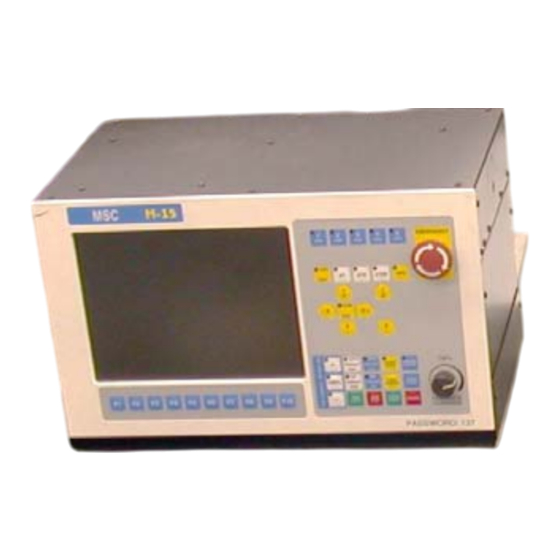
- Page 8 4th axis only. *Set the Machine Configuration as below for the *DO NOT CHANGE THE VALUES FOR 1, 2, 3 AXIS! Go to the proper screens as follows: F1<Setup>, F3<Config>, Password= 137 <Enter>; then F3<Params> or F2<Machine> as instructed below. Always be sure to use F10 <Save>...
- Page 9 The degree per minute is the input required for the feedrate. 4. From the main screen of CNC7, press F6<Edit> and open the file c:\cnc7\cnc7.hom. Add these lines at the end of the file for homing the rotary axis. If you have a home/limit switch add these lines - M92/B M26/B If you don't have a home/limit switch just add this line - M26/B Special Note For Golden Sun with DC brush motor:...
- Page 10 The final M-15 with 4 Axis Upgrade C:\My Documents\M15 4th AXIS UPGRADE.doc Rob Page 10 5/21/2004...
Need help?
Do you have a question about the M15 and is the answer not in the manual?
Questions and answers