
Related Manuals for Advansus i945GM3-DCQI

Summary of Contents for Advansus i945GM3-DCQI
- Page 1 Intel® 945GM μFC-PGA 478 Core Duo / Core Solo / Core 2 Duo Mini ITX Motherboard User’s Manual Ver. 1.00...
-
Page 2: Table Of Contents
Contents Safety Information ......................4 Technical Support ......................5 Conventions Used in This Guide ..................5 Packing List ........................6 Revision History .......................7 Specifications Summary....................8 Block Diagram.........................11 Production Introduction ....................13 Before you Proceed ....................13 Motherboard Overview....................14 1.2.1 Placement Direction ........................14 1.2.2 Screw Holes ........................... 14 Motherboard Layout ....................15... - Page 3 LCD Inverter Connector (JBKL1)....................40 1.8.12 Digital I/O Connector (JDIO1) ....................41 1.8.13 LVDS Connector (JLVDS1) ....................... 41 1.8.14 Serial ATA Connector [Red] (SATA1, SATA2) ................42 1.8.15 Digital Audio Connector (SPDIF_OUT1) ................... 42 1.8.16 USB 2.0 Connector (USB45, USB67)..................43 i945GM3-DCQI...
-
Page 4: Safety Information
Safety Information Electrical safety To prevent electrical shock hazard, disconnect the power cable from the electrical outlet before relocating the system. When adding or removing devices to or from the system, ensure that the power cables for the devices are unplugged before the signal cables are connected. If possible, disconnect all power cables from the existing system before you add a device. -
Page 5: Technical Support
If a problem arises with your system and no solution can be obtained from the user’s manual, please contact your place of purchase or local distributor. Alternatively, please try the following help resources for further guidance. Visit the Advansus website for FAQ, technical guide, BIOS updates, driver updates, and other information: http://www.advansus.com.tw/Support/Support.asp... -
Page 6: Packing List
Packing List Before you begin installing your single board, please make sure that the following materials have been shipped: 1 x i945GM3-DCQI Mini ITX Main board 1 x CD-ROM contains the followings: - User’s manual (this manual in PDF file) -... -
Page 7: Revision History
User’s Manual Revision History Revision Revision History Date V 1.0 First release for PCB 1.00 November 09, 2007 i945GM3-DCQI... -
Page 8: Specifications Summary
Specifications Summary Supports Intel® μFC-PGA 478 Core Duo / Core Solo / Core 2 Duo CPU with 65nm process technology Intel® 82945GME Express Chipset Two 240-pin DIMMs up to 4GB Dual Channel DDR2 533/667 SDRAM DVI, 2-CH 24-bits LVDS, Dual View... - Page 9 Dual channel 18/24-bit Chrontel CH7307C DVI transmitter up to 165M pixels/second Audio Audio Codec Realtek ALC888 5.1+2CH Audio Codec with two independent audio stream Mic in, Line in, Line out Audio Interface TPA3005D2 Stereo 5Watt per channel Audio Amplifier i945GM3-DCQI...
- Page 10 Specifications Summary Ethernet LAN1 Realtek RTL8111B Gigabit LAN Mechanical & Environmental Power Type Operating Temperature 0~60°C (32~140°F) 0%~90% relative humidity, non-condensing Operating Humidity 6.69" x 6.69" (170 mm x 170 mm) Size (L x W) Weight 0.88 lbs (0.4 Kg)
-
Page 11: Block Diagram
User’s Manual Block Diagram i945GM3-DCQI... - Page 12 This chapter describes the main board features and the new technologies it supports. Product Product introduction introduction...
-
Page 13: Production Introduction
Before you install or remove any component, ensure that the ATX power supply is switched off or the power cord is detached from the power supply. Failure to do so may cause severe damage to the motherboard, peripherals, and/or components. i945GM3-DCQI... -
Page 14: Motherboard Overview
1.2 Motherboard Overview Before you install the motherboard, study the configuration of your chassis to ensure that the motherboard fits into it. Refer to the chassis documentation before installing the motherboard. Make sure to unplug the power cord before installing or removing the motherboard. -
Page 15: Motherboard Layout
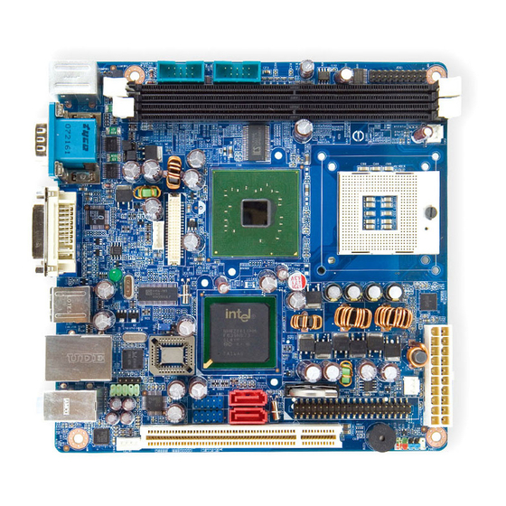
User’s Manual 1.3 Motherboard Layout i945GM3-DCQI... -
Page 16: Layout Content List
1.3.1 Layout Content List Slots Label Function Note Page Compact Flash connector (Rear side) DIMM1 240-pin SODIMM slot 1 DIMM2 240-pin SODIMM slot 2 PCI1 PCI slot Jumpers Label Function Note Page CLRTC Clear CMOS 3 x 1 header, pitch 2.54mm... - Page 17 HIROSE DF13S-40DP-1.25V SATA1,2 Serial ATA connectors 1,2 [red] 7-pin header SPDIF_OUT1 Digital Audio connector 4 x 1 header, pitch 2.54mm USB45 USB 2.0 connector 5 x 2 header, pitch 2.54mm USB67 USB 2.0 connector 5 x 2 header, pitch 2.54mm i945GM3-DCQI...
-
Page 18: Central Processing Unit (Cpu)
1.4 Central Processing Unit (CPU) The motherboard comes with a surface mount 478-pin socket designed for the Intel® Core Duo / Core Solo / Core 2 Duo CPU with 65nm process. Take one of the marked corner (with gold triangle) on the CPU. -
Page 19: Installing The Cpu
Installing the CPU Locate the CPU socket on the motherboard. Before installing the CPU, make sure that the socket box is facing towards you. The processor socket comes with a screw to secure the processor, please unlock the screw first. i945GM3-DCQI... - Page 20 Position the CPU above the socket and the gold triangular mark on the CPU must align with pin 1 of the CPU socket. Carefully insert the CPU into the socket until it fits in place ‘Gold mark’. Turn the screw to the lock position.
-
Page 21: Installing The Cpu Heatsink And Fan
Orient the heatsink and fan assembly such that the CPU fan cable is closest to the CPU fan connector. Make sure each fastener is oriented as shown, with the narrow groove directed outward. i945GM3-DCQI... - Page 22 Rotate each fastener clockwise to secure the heatsink and fan assembly in place. Connect the CPU fan cable to the connector on the motherboard labelled CPU_FAN. Do not forget to connect the fan cables to the fan connectors. Insufficient air flow inside the system may damage the motherboard components, and hardware monitoring errors can occur if you fail to plug this connector.
-
Page 23: Uninstalling The Cpu Heatsink And Fan
Pull up four fasteners to disengage the heatsink and fan assembly from the motherboard. Carefully remove the heatsink and fan assembly from the motherboard. Refer to the documentation in the boxed or stand-alone CPU fan package for detailed information on CPU fan installation. i945GM3-DCQI... -
Page 24: System Memory
1.5 System Memory 1.5.1 DIMM Sockets Location The motherboard comes with four 240-pin Double Data Rate 2 (DDR2) Dual Inline Memory Modules (DIMM) sockets. A DDR2 module has the same physical dimensions as a DDR DIMM but has a 240-pin footprint compared to the 184-pin DDR DIMM. -
Page 25: Memory Configurations
Recommended memory configuration Sockets Mode DIMM1 DIMM2 Single-channel Installed - Installed - Memory frequency/CPU FSB synchronization CPU FSB DDR2 DIMM Type Memory Frequency 533/667MHz DDR2 533 Max clock Freq: 266MHZ; 533Mb/s DDR2 667 Max clock Freq: 333MHZ; 667Mb/s i945GM3-DCQI... -
Page 26: Installing A Ddr2 Dimm
1.5.3 Installing a DDR2 DIMM Make sure to unplug the power supply before adding or removing DIMMs or other system components. Failure to do so may cause severe damage to both the motherboard and the components. Unlock a DIMM socket by pressing the... -
Page 27: Expansion Slots
After installing the expansion card, configure it by adjusting the software settings. Turn on the system and change the necessary BIOS settings if any. Assign an IRQ to the card if needed. Refer to the tables on the next page. Install the software drivers for the expansion card. i945GM3-DCQI... -
Page 28: Standard Interrupt Assignments
* There IRQs are usually available for ISA or PCI device. 1.6.4 PCI Slots i945GM3-DCQI has one PCI slots. The PCI slots support cards such as a LAN card, SCSI card, USB card, and other cards that comply with PCI specifications. -
Page 29: Jumpers
Hold down the <Del> key during the boot process and enter BIOS setup to re-enter data. Except when clearing the CMOS, never remove the cap on CLRTC jumper default position. Removing the cap will cause system boot failure! Normal (Default) Clear RTC i945GM3-DCQI... -
Page 30: Com1 Ri/+5V/+12V Selection (Jcompwr1, Jcompwr2)
1.7.2 COM1 RI/+5V/+12V Selection (JCOMPWR1, JCOMPWR2) JCOMPWR1 JCOMPWR2 (Default) +12V Ring JCOMPWR1 JCOMPWR2 1.7.3 COM2 RI/+5V/+12V Selection (JCOMPWR1, JCOMPWR2) JCOMPWR1 JCOMPWR2 (Default) +12V Ring JCOMPWR1 JCOMPWR2... -
Page 31: Com3 Ri/+5V/+12V Selection (Jcompwr3, Jcompwr4)
User’s Manual 1.7.4 COM3 RI/+5V/+12V Selection (JCOMPWR3, JCOMPWR4) JCOMPWR3 JCOMPWR4 (Default) +12V Ring 1.7.5 COM4 RI/+5V/+12V Selection (JCOMPWR3, JCOMPWR4) JCOMPWR3 JCOMPWR4 (Default) +12V Ring i945GM3-DCQI... -
Page 32: Connectors
1.8 Connectors 1.8.1 Rear Panel Connectors Label Function Description KBMS PS/2 mouse connector The standard PS/2 mouse DIN connector is for a PS/2 mouse. COM12 Serial port connector x 2 D-sub 9-pin, male VGA_DVI-D1 DVI port LAN_USB1 LAN (RJ-45) connector... - Page 33 These four 4-pin Universal Serial Bus (USB) ports are available for connecting USB 2.0 devices. VGA_DVI-D1 VGA port This 15-pin port is for a VGA monitor or other VGA-compatible devices. KBMS PS/2 KB connector This port is for a PS/2 keyboard i945GM3-DCQI...
-
Page 34: Front Panel Audio Connector (Aafp1)
1.8.2 Front Panel Audio Connector (AAFP1) This connector is for a chassis-mounted front panel audio I/O module that supports either HD Audio or legacy AC ‘97 (optional) audio standard. Connect one end of the front panel audio I/O module cable to this connector. -
Page 35: Atx Power Connector (Atxpwr1)
300W for a fully configured system. The system can become unstable and might experience difficulty powering up if the power supply is inadequate. You must install a PSU with a higher power rating if you intend to install additional devices. i945GM3-DCQI... -
Page 36: Chassis Fan Connector (Cha_Fan)
1.8.4 Chassis Fan Connector (CHA_FAN) 1.8.5 CPU Fan Connector (CPU_FAN) Do not forget to connect the fan cables to the fan connectors. Insufficient air flow inside the system may damage the motherboard components, and hardware monitoring errors can occur if you fail to plug this connector. -
Page 37: Serial Port 3 Connector (Com3)
User’s Manual 1.8.6 Serial Port 3 Connector (COM3) 1.8.7 Serial Port 4 Connector (COM4) i945GM3-DCQI... -
Page 38: System Panel Connector (F_Panel1)
1.8.8 System Panel Connector (F_PANEL1) This connector supports several chassis-mounted functions. System Power LED (2-pin PWRLED) This 2-pin connector is for the system power LED. Connect the chassis power LED cable to this connector. The system power LED lights up when you turn on the system power, and blinks when the system is in sleep mode. -
Page 39: Primary Ide Connector (Ide1)
User’s Manual 1.8.9 Primary IDE Connector (IDE1) Orient the red markings (usually zigzag) on the IDE cable to Pin 1.8.10 Amplifier Connector (JAMP1) i945GM3-DCQI... -
Page 40: Lcd Inverter Connector (Jbkl1)
1.8.11 LCD Inverter Connector (JBKL1) Signal Description Signal Signal Description For inverter with adjustable Backlight function, it is possible to control the LCD brightness through the VR signal. Vadj=0.75V ~ 4.25V (Recommended: 4.7KΩ, > 1/16W) ENBKL LCD backlight ON/OFF control signal... -
Page 41: Digital I/O Connector (Jdio1)
User’s Manual 1.8.12 Digital I/O Connector (JDIO1) 1.8.13 LVDS Connector (JLVDS1) i945GM3-DCQI... -
Page 42: Serial Ata Connector [Red] (Sata1, Sata2)
1.8.14 Serial ATA Connector [Red] (SATA1, SATA2) SATA1 SATA2 SATA1 SATA2 Install the Windows® 2000 Service Pack 4 or the Windows® XP Service Pack1 before using Serial ATA. When using the connectors in Standard IDE mode, connect the primary (boot) hard disk drive to the SATA1 connector. -
Page 43: Usb 2.0 Connector (Usb45, Usb67)
These USB connectors comply with USB 2.0 specification that supports up to 480 Mbps connection speed. USB45 USB67 USB67 USB45 Never connect a 1394 cable to the USB connectors. Doing so will damage the motherboard! The USB module is purchased separately. i945GM3-DCQI...
Need help?
Do you have a question about the i945GM3-DCQI and is the answer not in the manual?
Questions and answers