Table of Contents
Advertisement
Quick Links
Installation, Operation, and Maintenance Instructions
Instruction Manual Catalog No. 358013-07
This manual is for use only with the following catalog numbers:
358501-###-##
358502-###-##
358001
358002
358006
358007
20358024
20358028
The "#" symbol represents a variable in the catalog number.
See Section 1.6, Catalog Number Configurations on page 1-12.
For assistance in using or servicing this instrument contact:
Helix Technology Corporation
Colorado Operations
Customer Service Department
6450 Dry Creek Pkwy
Longmont, Colorado 80503-9501 USA
Telephone (303) 652-4400
FAX (303) 652-2844
email: salesco@helixtechnology.com
Granville-Phillips, Micro-Ion, and Convectron are registered trademarks of Helix Technology Corporation.
Series 358
1Granville-Phillips Micro-Ion
Vacuum Measurement System
358503-###-##
20358024-T1
358003
358004
20358018
20358023
20358029
20358031
GRANVILLE-PHILLIPS
HELIX TECHNOLOGY CORPORATION
© Copyright Helix Technology Corporation 1996-2002
All Rights Reserved
Revised: June 2002
®
358506-T2
358035
Advertisement
Chapters
Table of Contents
Troubleshooting

Related Manuals for Granville-Phillips 358 Series


Summary of Contents for Granville-Phillips 358 Series
- Page 1 6450 Dry Creek Pkwy Longmont, Colorado 80503-9501 USA Telephone (303) 652-4400 FAX (303) 652-2844 email: salesco@helixtechnology.com GRANVILLE-PHILLIPS HELIX TECHNOLOGY CORPORATION © Copyright Helix Technology Corporation 1996-2002 All Rights Reserved Revised: June 2002 Granville-Phillips, Micro-Ion, and Convectron are registered trademarks of Helix Technology Corporation.
- Page 2 Declaration of Conformity In accordance with ISO/IEC Guide 22 and EN45014 ® Product Name(s): Granville - Phillips Series 360/370 Stabil-Ion Vacuum Gauge Controllers 360101 360102 360187 360188 20360136 Product Number(s): 370101 370102 20360150 20360174 20360175 20360182 20360184 20360185 20370134 20370135 360###-###-## 370###-###-## 370505-010-T1...
-
Page 3: Table Of Contents
Table of Contents Safety..................v Safety Instructions . - Page 4 Table of Contents 2.4.4 Handshake Line Control Switches for RS-232 Module ....... 2-12 2.4.5 Invert RTS Switch for RS-232 Module .
- Page 5 Table of Contents 4.7.2 Manual Override ............4-16 4.7.3 To Display a Setpoint.
- Page 6 Table of Contents Series 358 Micro-Ion Vacuum Measurement System November, 2001...
-
Page 7: Safety
Safety Safety Instructions START BY READING THESE IMPORTANT SAFETY INSTRUCTIONS AND NOTES collected here for your convenience and repeated with additional information at appropriate points in these instructions. These safety alert symbols in this manual or on the Product rear panel, mean caution - personal safety, property damage or danger from electric shock. - Page 8 Safety Do not substitute parts or modify instrument. Because of the danger of introducing additional hazards, do not install substitute parts or perform any unauthorized modification to the product. Return the product to a service facility designated by Helix Technology for service and repair to ensure that safety features are maintained.
- Page 9 Safety Proper Grounding: All components of a vacuum system used with this or any similar high voltage product must be maintained at earth ground for safe operation. The power cord of this product shall be connected only to a properly grounded outlet.
- Page 10 Safety Do not operate in an explosive atmosphere. Do not operate the product in the presence of flammable gases or fumes. Operation of any electrical instrument in such an environment constitutes a definite safety hazard. Do not use the product to measure the pressure of explosive or combustible gases or gas mixtures.
-
Page 11: Certification
Helix Technology Corporation provides an eighteen (18) month warranty from the date of shipment for new Granville-Phillips Products. The Helix Technology Corporation General Terms and Conditions of Sale provides the complete and exclusive warranty for Helix Technology Corporation's products. This document is located on our web site at www.helixtechnology.com, or may be obtained by contacting Helix Technology... - Page 12 NOTES Series 358 Micro-Ion Vacuum Measurement System November, 2001...
-
Page 13: Chapter 1 System Components
Chapter 1 System Components The Series 358 Micro-Ion Vacuum Measurement System can operate one Micro-Ion Gauge along with two Convectron Gauges simultaneously. Pressure readout is via three front panel displays, analog output, and available computer interface. The Series 358 Micro-Ion Vacuum Measurement System is a modular instrument that can be easily customized to fit most user's exact needs. -
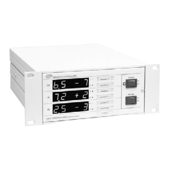
Page 14: Controller Front Panel
System Components 1.2 Controller Front Panel Figure 1-2 358 Controller Front Panel. 1. Micro-Ion display 6. Degas “momentary” On/Off switch 2. Convectron Gauge A display 7. Degas LED 3. Convectron Gauge B display 8. Process Control channel labels 4. Unit of measure label, Torr, mbar or Pascal, user selectable 9. -
Page 15: Controls Inside Front Panel
System Components 1.2.1 Controls Inside Front Panel Open the front panel door to access these controls. Figure 1-3 358 Controller Front Panel (door open). 1. Filament select switch: Filament 1, Filament 2, or both 2. Sensor adjustment 3. Pressure range selector 4. -
Page 16: Top View Of Controller (Cover Removed)
System Components 1.2.2 Top View of Controller (Cover Removed) Figure 1-4 358 Controller Top View (cover removed). 1. Power supply board 2. Process Control board 3. Convectron board 4. Electrometer board 5. Filament/Grid Supply board 6. RS-232 board Series 358 Micro-Ion Vacuum Measurement System November, 2001... -
Page 17: Options
System Components 1.3 Options 1.3.1 Process Control Relay A 2, 6 or 1-4 channel process control relay option can either be factory installed or added at any time by the user. The set points are adjustable from atmosphere to 1 x 10 Torr with override switches and front panel status indication. -
Page 18: Specifications
System Components 1.3.2.2 RS-232 Specifications Table 1-1 RS-232 Specifications. Item Specification Format EIA standard RS-232-C, half duplex, asynchronous. Data Rates 75,150,300,600,1200,2400,4800,9600 baud. Character length 7 or 8 bit ASCII, switch selectable. Parity Odd, even, or none, switch selectable. Stop bits 1 or 2. -
Page 19: Power On/Off
System Components 1.3.3 Power On/Off To turn on the Series 358 Micro-Ion Vacuum Measurement System depress the top half of the power switch located on the rear panel of the Controller (see Figure 1-5 on page 1-5). 1.3.4 Remote Input/Output Two TTL compatible inputs are provided through the rear panel allowing control of the Micro-Ion Gauge and degas. -
Page 20: System Specifications
System Components 1.4 System Specifications Table 1-4 Specifications for the Series 358 Micro-Ion Vacuum Measurement System. Micro-Ion System Pressure Range for N /Air Lower Measurement Limit <1 x 10 Torr (1.3 x 10 mbar) (1 x 10 Upper Measurement Limit Atmosphere 358 Controller Electronic Accuracy... - Page 21 System Components Controller Options Process Control Relay Configuration SPDT, Form C Contact Rating 5A @ 120 Vac, 4A @ 240 Vac resistive or 5A @ 30 Vdc Channels 6 maximum, 2 per operating gauge maximum Hysteresis Setpoint Adjustment Digital, 2 significant digits plus exponent Digital Interfaces RS-232 or RS-485/422 Dual Convectron Gauge...
-
Page 22: Dimensions
System Components Ion Gauge Pressure Range* Pressure Range Designation (medium vacuum) (high vacuum) (ultrahigh vacuum) 20 mA Emission Current 1 mA 4 mA Recommended Upper Limit, Torr 5 x 10 8 x 10 2 x 10 Recommended Lower Limit, Torr 1 x 10 1 x 10 less than 1 x 10... -
Page 23: Micro-Ion Gauge With Connector
System Components 1.5.2 Micro-Ion Gauge with Connector The dimensions of the Micro-Ion Gauge are shown in Figure 1-10. Dimensions are in cm (in.). H dimensions are given in Table 1-5. Figure 1-10 Micro-Ion Gauge Dimensions. 1.5.3 Convectron Gauge with Connector The dimensions of the Convectron Gauge are shown Figure 1-11. -
Page 24: Catalog Number Configurations
System Components 1.6 Catalog Number Configurations Series 358 Micro-Ion Gauge Controller with 3-line display (CE–Marked) Choose one of the basic controllers and add the options below to create your catalog number. Controller with half-rack mount brackets 358501 - # # # - # # Controller with left mount for 19-inch rack 358502 - # # # - # # Controller with center mount for 19-inch rack... -
Page 25: Chapter 2 Initial Setup Procedures
Chapter 2 Initial Setup Procedures 2.1 Controller Setup Now is a convenient time to make any required switch changes before mounting the Controller in its desired location. If the pressure display units of measure are correct (see Figure 2-1), and you do not wish to change the degas power timer from the factory setting of 10 minutes, skip to Chapter 3 Installation. -
Page 26: Pressure Units Setup
Initial Setup Procedures Remove the four Phillips head screws identified in Figure 2-2. If the unit is equipped with a rear bracket instead of one rear screw, unfasten the Phillips head screw on the bracket, and slide off the bracket. 2.2 Pressure Units Setup If units of measure are as desired (see Figure 2-1 on page 2-1), skip to Section 2.2.1.2 Changing the Display Update Rate on Electrometer Module on page 2-3. -
Page 27: Overpressure Shutdown Adjustment
Initial Setup Procedures 2.2.1.1 Overpressure Shutdown Adjustment This control is factory-set so the ion gauge will shut down when the pressure rises above the levels given in Table 2-1. Table 2-1 Relay Ratings. Pressure Range Designation (medium vacuum) (high vacuum) (ultrahigh vacuum) 20 mA Emission Current... -
Page 28: Changing Units Of Measure For The Convectron Gauge
Initial Setup Procedures 2.2.2 Changing Units of Measure for the Convectron Gauge Your instrument will have been shipped from the factory pre-set to display the units of measure, Torr, millibar, or Pa, that you requested. If you wish to change units, proceed as follows: Shut off power to the Controller. -
Page 29: Process Control Channel Identification Windows
Initial Setup Procedures 2.3.1 Process Control Channel Identification Windows A channel identification label is included in the accessory kit to enable you to customize your Series 358 Micro-Ion Vacuum Measurement System for your application (see Figure 2-6). Figure 2-6 Process Control Channel Identification Windows on 358 Controller Front Panel. 2.3.2 Developing a Logic Diagram of Control Logic Prior to connecting the Process Controls to the system, it is recommended that the following steps be followed. - Page 30 Initial Setup Procedures NOTE 1: Normally Open Common Channel 1 is user- Normally Closed assignable to IG1 or to IG2, or to IG1 Note 1 2 independent sets NO C NC and IG2. of relay contacts CH. 1 T W P Channel 2 is user- PROCESS CONTROL CH.
-
Page 31: Ion Gauge Assignment For Process Control
Initial Setup Procedures 2.3.3 Ion Gauge Assignment for Process Control A maximum of 6 Process Control channels are available depending on the particular option you have specified. A channel is defined as the combination of vacuum gauge indication setpoint circuitry and the associated relay which is actuated when the pressure indication corresponds to the setpoint. -
Page 32: Relay Polarity Setting
Initial Setup Procedures 2.3.4 Relay Polarity Setting The relays can be set to activate as pressure either rises above or falls below the setpoint. A DIP switch is provided for each channel. Refer to the numbers on the printed circuit board—not on the switch body— for the channel number. -
Page 33: Process Control Tips
Initial Setup Procedures 2.3.5 Process Control Tips The Process Control override switches can be used to hold relays on or off during initial turn on or during non-typical process conditions. When IG1 and IG2 are off, channels 1 and 2 are inoperative. When Convectron Gauges are disconnected, channels 3-6 are inoperative. -
Page 34: Connector Pinouts For The Rs-232 Computer Interface
Initial Setup Procedures 2.4.1 Connector Pinouts for the RS-232 Computer Interface This factory- or field-installed capability produces the signals shown in Table 2-6. A mating DB-25S connector is supplied in the hardware kit. Use shielded cable to minimize electromagnetic radiation or susceptibility. Table 2-6 RS-232 Connector Pin Assignments. -
Page 35: Character Framing For Rs-232 Module
Initial Setup Procedures 2.4.2.2 Character Framing for RS-232 Module Switches 3-5 control number of characters, parity, and number of stop bits: Table 2-8 Character Framing for RS-232 Module. Character Bits Parity Stop Bits None* 1* or 2 Even None Even Even factory setting Figure 2-14... -
Page 36: Handshake Line Control Switches For Rs-232 Module
Initial Setup Procedures 2.4.4 Handshake Line Control Switches for RS-232 Module Refer to Section 3.7, page 3-12, for more detailed information on the handshaking mechanism. Table 2-10 Inputs to 358 for RS-232. Internal Switch Factory Line Switch Description Function Setting CLEAR to SEND CTS=1 and DSR=1: Both ON*... -
Page 37: Invert Rts Switch For Rs-232 Module
Initial Setup Procedures 2.4.5 Invert RTS Switch for RS-232 Module As shipped from the factory, the request-to-send (RTS) control line is set to operate as a modem line per the RS-232 standard. In some implementations it is necessary to invert this line and hook it directly to the clear-to-send (CTS) line of the host computer. -
Page 38: Computer Interface Setup
Initial Setup Procedures 2.5 RS-485 Computer Interface Setup If your Controller does not have this capability, skip to Section 2.6 on page 2-17. RS-485 capability permits data output to, and gauge control by, a host computer. Output is by a command-response mechanism. -
Page 39: Address
Initial Setup Procedures Data Data TØ Data Figure 2-19 RS-485 Data Timing. TØ = 10 to 13 mS + 10 bits with S2.1 OFF. TØ = 700 µS with S2.1 ON. T1 = 300 µS minimum. 2.5.2 RS-485 Address The Address switch on the RS-485 module on the back of the Controller (see Figure 2-18 on page 2-14) and Switch S1 (see Figure 2-20) determine the RS-485 module's address. -
Page 40: Selecting The Byte Format For Rs-485 Module
Initial Setup Procedures 2.5.3 Selecting the Byte Format for RS-485 Module 2.5.3.1 Baud Rate for RS-485 Baud rate for the RS-485 computer interface is determined by S2.6, S2.7, S2.8. Table 2-14 Baud Rate for the RS-485 Module. S2.6 S2.7 S2.8 Baud Rate 19200* 9600... -
Page 41: Replacing Controller Cover
Initial Setup Procedures 2.6 Replacing Controller Cover Assuming you have completed the above instructions, the Controller setup is now complete. Replace the top cover. Make sure the door hinge pin is seated correctly. Replace the four top cover Phillips head screws (or three screws plus bracket screw). - Page 42 NOTES 2-18 Series 358 Micro-Ion Vacuum Measurement System November, 2001...
-
Page 43: Chapter 3 Installation
Chapter 3 Installation It is the installer's responsibility to ensure that the automatic signals provided by the product are always used in a safe manner. Carefully check the system programming before switching to automatic operation. Where an equipment malfunction could cause a hazardous situation, always provide for fail-safe operation. -
Page 44: Environmental Conditions
Installation 3.1.3 Environmental Conditions ■ Indoor Use. ■ Altitude up to 2000 meters. ■ Temperature 0 °C to 40 °C. ■ Maximum relative humidity 80% for temperatures up to 31 °C decreasing linearly to 50% relative humidity at 40 °C. ■... -
Page 45: Mounting Configurations
Installation 3.2.3 Mounting Configurations Figure 3-1 illustrates the various configurations available for mounting the Series 358 Micro-Ion Vacuum Gauge Controller. NOTE: The Series 358 Micro-Ion Vacuum Measurement System should be mounted in a location with free air flow and ambient temperature less than 40 Figure 3-1 358 Controller Mounting Configurations. -
Page 46: Line Voltage
Installation 3.2.4 Line Voltage The Series 358 Controller will operate over a line voltage range of 100 Vac to 240 Vac, 50-60 Hz. All that is required is that a line cord be selected to match your available power receptacle to the power input connector located on the rear of the Controller. -
Page 47: Convectron Gauge Installation
Installation 3.3 Convectron Gauge Installation When high voltage is present, all exposed conductors of a vacuum must be maintained at earth ground. Under certain conditions, dangerous high voltage can be coupled directly to an ungrounded conductor through a gas almost as effectively as through a copper wire connection. This hazard, which is not peculiar to this product, is a consequence of the ability of an electric current to flow through a gas under certain circumstances. -
Page 48: Mounting Options
Installation 3.3.1 Mounting Options 3.3.1.1 Compression Mount/Quick Connect Do not use for positive pressure applications. The gauge may be forcefully ejected. The gauge port is designed to fit a standard 1/2 in. compression/quick connect mounting such as an Ultra-Torr fitting. Remove the caplug from the gauge tube port, insert the gauge tube port into the compression fitting and finger tighten the press ring. -
Page 49: Grounding The System
Installation 3.4 Grounding the System Connect a heavy duty ground wire #12 AWG or larger from the ground lug on the back of the Controller (see Figure 1-5 on page 1-5) to your facility grounding electrode system. This will provide an earth ground for the Controller in the event the interconnect cables are not in place. -
Page 50: Procedure For Testing Grounding Of Systems
Installation 3.4.1.1 Procedure for Testing Grounding of Systems Use the following procedure to test each of your vacuum systems that incorporate an ionization gauge. NOTE: This procedure uses a conventional volt-ohm meter (VOM) and a resistor (10 ohm, 10 watt). With the Controller turned off, test for both DC and AC voltages between the metal parts of the vacuum chamber and the power supply chassis. -
Page 51: Connecting Analog Outputs
Installation If the voltage calculation in Step 3 is less than 0.83, due to the placement of the shunt, it complicates the measurement. The commonality of the grounds may be satisfactory and the coupling poor, or the commonality could be poor! Your electrician should be asked to check the electrical continuity between these two ground systems. -
Page 52: Convectron Gauge Analog Output Signal
Installation 3.5.2 Convectron Gauge Analog Output Signal If you have Convectron Gauge capability installed, signal voltages proportional to the logarithm of the Convectron Gauge display indications are provided on the back of the Convectron Gauge module via a standard 1/8” miniature phono jack. Two mating connectors are supplied with this capability. -
Page 53: Connecting Process Control Relays
Installation 3.6 Connecting Process Control Relays Instructions for setting up this module are in Section 2.3 Process Control Setup on page 2-4. The process control connector is embossed with letters identifying corner pins. Table 3-2 shows the letters designating the 3 pins assigned to each of the 6 setpoint channels. Table 3-2 Process Control Output Connector Pin Assignments. -
Page 54: Connecting The Rs-232 Computer Interface
Installation 3.7 Connecting the RS-232 Computer Interface Instructions for setting up this interface are in Section 2.4 on page 2-9. The DTR line is set true on power up to indicate it is on line. When the 358 receives a start bit on the received data line it will input and buffer a character. -
Page 55: Connecting The Rs-485 Computer Interface
Installation 3.8 Connecting the RS-485 Computer Interface Instructions for setting up this interface are in Section 2.5 on page 2-14. Connectors J1 and J2 on the rear panel are wired in parallel and are interchangeable. Connection can easily be made by “daisy chaining” gauge Controllers together with the signal from the host computer going into one connector then out the other to another gauge Controller and so on. - Page 56 NOTES 3-14 Series 358 Micro-Ion Vacuum Measurement System November, 2001...
-
Page 57: Chapter 4 Preparing For Operation
Chapter 4 Preparing for Operation 4.1 Preparing for Pressure Measurement The steps in this Section (4.1) assume: Your 358 Micro-Ion Vacuum Gauge System has been properly set up and installed per the instructions in Chapters 2 and 3. The gas in your vacuum system is air or N . -
Page 58: Alternate On/Off Gauge Control
Preparing for Operation 4.1.1 Alternate ON/OFF Gauge Control The 358 Gauges may be turned on and off in the following ways: ■ Using the front panel Micro-Ion Gauge “momentary” GAUGE On/Off switch. See Figure 4-2. ■ Automatically using the Auto On function of the Convectron Gauge module. -
Page 59: Preparing For Convectron Gauge Operation
Preparing for Operation Figure 4-4 Ionization Gauge Analog Output vs. Pressure. 4.3 Preparing for Convectron Gauge Operation Convectron Gauge pressures are indicated on lines A and B of the Controller display. Using the N calibration to pressurize a vacuum system above about 1 Torr with certain other gases can cause dangerously high pressures which may cause explosion of the system. -
Page 60: Understanding Pressure Measurement In Gases Other Than Nitrogen (Or Air)
Preparing for Operation 4.3.1 Understanding Pressure Measurement in Gases other than Nitrogen (or Air) Convectron Gauges are thermal conductivity gauges of the Pirani type. These gauges transduce gas pressure by measuring the heat loss from a heated sensor wire maintained at constant temperature. For different gases, the heat loss is different at any given true pressure and thus the pressure indication can be very different. - Page 61 Preparing for Operation Figures 4-5 through 4-10 show the true pressure vs. indicated pressure for eleven commonly used gases. The following list will help to locate the proper graph: Pressure vs. Indicated N Pressure Curve. Table 4-1 Fig. No. Pressure Range and Units Gases to 10 Torr to 1000 Torr...
-
Page 62: Examples
Preparing for Operation 4.3.2 Examples Example 1 – Maximum safe indicated pressure. Assume a certain system will withstand an internal pressure of 2000 Torr or 38.7 psia. For safety, you wish to limit the maximum internal pressure to 760 Torr during backfilling. Assume you wish to measure the pressure of Freon 22. - Page 63 Preparing for Operation , air freon 22 freon 12 Do not use this data with transducers other than the G-P Series 275 ® Convectron Gauge. Pressure units equivalence: µ m Hg = 1 mTorr = 1 x 10 Torr µ 1000 m Hg = 1 Torr Indicated Pressure (Torr)
- Page 64 Preparing for Operation 1000 freon 12 , air freon 12 Use only when gauge axis is horizontal Do not use this data with transducers other than the G-P Series 275 ® Convectron Gauge. Pressure units equivalence: µ m Hg = 1 mTorr = 1 x 10 Torr µ...
- Page 65 Preparing for Operation 1000 , air freon 22 Use only when gauge axis is horizontal Do not use this data with transducers other than the G-P Series 275 ® Convectron Gauge. Pressure units equivalence: µ m Hg = 1 mTorr = 1 x 10 Torr µ...
- Page 66 Preparing for Operation , air freon 22 freon 12 Do not use this data with transducers other than the G-P Series 275 ® Convectron Gauge. Pressure units equivalence: 1 mbar = 100 pascal Indicated Pressure (mbar) (nitrogen equivalent) Figure 4-8 Convectron Gauge Indicated vs.
- Page 67 Preparing for Operation 1000 freon 12 , air Use only when gauge axis is horizontal freon 12 Do not use this data with transducers other than the G-P Series 275 ® Convectron Gauge. Pressure units equivalence: 1 mbar = 100 pascal 1000 Indicated Pressure (mbar) (nitrogen equivalent)
- Page 68 Preparing for Operation 1000 , air freon 22 Use only when gauge axis is horizontal Do not use this data with transducers other than the G-P Series 275 ® Convectron Gauge. Pressure units equivalence: 1 mbar = 100 pascal freon 22 1000 Indicated Pressure (mbar) (nitrogen equivalent)
-
Page 69: Ionization Gauge Auto Turn On/Off
Preparing for Operation 4.4 Ionization Gauge Auto Turn On/Off Warning – If used improperly, Convectron Gauges can supply misleading pressure indications that can result in dangerous overpressure conditions within the system. For use with gases other than air or N , consult the gas type correction charts in Section 4.3.1 on page 4-4. -
Page 70: Adjustment Of Convectron Gauge Zero And Atmospheric Pressure Indications
Preparing for Operation 4.5 Adjustment of Convectron Gauge Zero and Atmospheric Pressure Indications Using the N calibration to pressurize a vacuum system above about 1 Torr with certain other gases can cause dangerously high pressures which may cause explosion of the system. See Section 4.3.1 on page 4-4 before using with other gases. -
Page 71: Convectron Gauge Analog Output Signal
Preparing for Operation 4.6 Convectron Gauge Analog Output Signal If the Convectron Gauge capability is installed, a voltage output signal proportional to the common logarithm of the pressure indication is provided on the rear panel of the Convectron Gauge module via a standard 1/8 in. -
Page 72: Preparing For Process Control Operation
Preparing for Operation If the offset has been adjusted to other than 0V at 10 Torr (10 Pa), then the exponent value must be forced to -4 (-2 for Pa) when the pressure is at 1.0 x 10 Torr (10 Pa) by adding or subtracting a number other than -4 from the value of V. -
Page 73: To Modify A Setpoint
Preparing for Operation 4.7.4 To Modify a Setpoint Set the selector switch to the number of the channel you wish to modify (see Figure 4-15). Press and hold one of the setpoint Set pushbuttons for the direction you wish the setpoint to change. - Page 74 Preparing for Operation Definition: Display degas status. Modifiers: None Response: ASCII 1 if degas is on, 0 if degas is off. Example: From computer: DGS CRLF (Note: Spaces may be omitted.) From 358: 1CRLF (Indicating degas is on.) Definition: Display pressure reading. Modifiers: IG1 or IG2 or IG or CG1 or CG2.
-
Page 75: Preparing For Use Of The Rs-485 Computer Interface
Preparing for Operation Modifier = single digit (1 through 6); response = single ASCII digit, 0 if the corresponding relay is inactive, 1 if active. See Example 1. Modifier = B; response = a byte of data with bits 0 through 5 set/clear according to whether the corresponding relay is active/inactive. -
Page 76: Command Syntax For The Rs-485 Computer Interface
Preparing for Operation 4.9.1 Command Syntax for the RS-485 Computer Interface Definition: Turn degas on or off. Modifiers: ON or OFF. Response: OK if command accepted, or INVALID if rejected. Example: From computer: #AADG ON CR From 358: OKCR NOTES: Command is INVALID if IG is OFF. - Page 77 Preparing for Operation NOTES: The IG1 ON command will be rejected as INVALID if IG1 is already on, and IG1 OFF will be rejected if IG1 is already off. A response to the IG1 ON command of OK indicates only that a signal requesting that IG1 be turned on has been sent to the electrometer.
- Page 78 NOTES 4-22 Series 358 Micro-Ion Vacuum Measurement System November, 2001...
-
Page 79: Chapter 5 Operation
Chapter 5 Operation The instructions in this chapter assume the instructions for Setup, Installation, and Preparing for Operation have been completed. See Chapters 2, 3, and 4. Theory of operation information for the Micro-Ion Gauge, Convectron Gauge, Electrometer, and Process Control modules begins on page 5-6. 5.1 Operation of the Series 358 Micro-Ion Vacuum Measurement System 5.1.1 Turning On the Controller Press the top half of the power ON switch on the rear panel of the Controller (see Figure 5-5). - Page 80 Operation If you have Convectron Gauge capability installed and have prepared your system for automatic operation of the Micro-Ion Gauge(s) per Section 4.4 on page 4-13, the ionization gauge will turn on and off automatically. For manual operation, press the front panel GAUGE momentary rocker switch (see Figure 5-2 on page 5-1).
- Page 81 Operation 5.1.2 Micro-Ion Gauge On/Off The Micro-Ion Gauge can be turned on or off by the front panel GAUGE “momentary” rocker switch or by the remote input, or by the Convectron Gauge set point. To turn on the Micro-Ion Gauge from the front panel, press the GAUGE momentary rocker switch (see Figure 5-2).
-
Page 82: Operation Of Micro-Ion Gauge Electrometer Module
Operation 5.2 Operation of Micro-Ion Gauge Electrometer Module 5.2.1 Displaying Sensitivity with the Calibration Switch This switch is used for displaying pressure or gauge sensitivity. It is activated by setting to the on position. The function depends on the state of the Micro-Ion Gauge tube: If the tube is off, setting the switch ON displays the tube sensitivity in the display. -
Page 83: Filament Selection For The Micro-Ion Gauge Electrometer Module
Operation Table 5-2 Relative Gas Sensitivities. 0.18 1.12 0.30 1.16 0.35 1.29 0.46 1.42 1.00 1.94 1.00 2.50 1.01 2.87 5.2.4 Filament Selection for the Micro-Ion Gauge Electrometer Module 5.2.4.1 Filament Select Switch The Filament Select switch (see Figure 5-4) is used to operate each filament individually or both in series. -
Page 84: Theory Of Operation
Operation 5.3 Theory of Operation 5.3.1 Micro-Ion Gauge Theory of Operation The functional parts of a typical ionization gauge are the filament (cathode), grid (anode) and ion collector, which are shown schematically in Figure 5-5. These electrodes are maintained by the gauge Controller at +30, +180, and 0 volts, relative to ground, respectively. -
Page 85: Convectron Gauge Theory Of Operation
Operation 5.3.2 Convectron Gauge Theory of Operation The Convectron Gauge transducer is represented in Figure 5-6 as R1, R2, R3, and R4. These four resistances form the legs of a bridge circuit, with R1 designating the sensor wire of the transducer. R2 is a resistive network in the tube that compensates for changes in the ambient temperature. -
Page 86: Process Control Theory Of Operation
Operation 5.3.4 Process Control Theory of Operation The Process Control module contains a dedicated microcontroller and a non-volatile memory chip for storage of the setpoints. This chip has a rated life of 10,000 erase/write cycles for each setpoint, and will retain data for 10 years. Since data is read/written to this chip serially, it is necessary to store working copies of the setpoints in internal RAM memory. -
Page 87: Chapter 6 Service And Maintenance
Chapter 6 Service and Maintenance 6.1 Service Guidelines Some minor difficulties are readily corrected in the field. Each module has fault indicator LEDs which help localize failures. If a Qualified Service Person makes repairs at the component level, repairs properly made with equivalent electronic parts and rosin core solder do not void the warranty. -
Page 88: Damage Requiring Service
Service and Maintenance 6.2 Damage Requiring Service Disconnect this product from the wall outlet and any other power sources, and refer servicing to Qualified Service Personnel if any the following conditions exist: ■ The gauge cable or plug is damaged. ■... - Page 89 Service and Maintenance Symptom Possible Cause IG will not turn on, or turns on IG at too high pressure. briefly then shuts off. Auto turn off circuit in Convectron Gauge module is shutting off IG. Emission current setting wrong for pressure in gauge. Improper IG connector hookup.
-
Page 90: Overpressure Shutdown
Service and Maintenance 6.3 Overpressure Shutdown As pressure increases, the ion current to the collector increases until the high density of gas molecules begins to interfere with the ionization process. When some electrons cannot acquire sufficient energy to ionize the gas molecules, the collector current no longer increases with increasing pressure. -
Page 91: Troubleshooting The Convectron Gauge Module
Service and Maintenance 6.4 Troubleshooting the Convectron Gauge Module Table 6-3 Convectron Gauge Module Troubleshooting. Symptom Possible Cause Pressure reading grossly in error. Controller out of calibration. Unknown gas type. Gauge not mounted horizontally (see Section 3.3 on page 3-5). Sensor damaged (e.g., by reactive gas). -
Page 92: Cleaning Contaminated Convectron Gauges
Service and Maintenance 6.4.2 Cleaning Contaminated Convectron Gauges The fumes from solvents such as trichloroethylene, perchlorethylene, toluene, and acetone can be dangerous to health if inhaled. If used, use only in well- ventilated area exhausted to the outdoors. Acetone and toluene are highly flammable and should not be used near an open flame or energized electrical equipment. -
Page 93: Troubleshooting
Service and Maintenance 6.6 RS-232 Troubleshooting Because the RS-232 “standard” is found in a bewildering array of configurations, the first thing to do if trouble arises is check the following configuration options: Check switch settings. Be sure baud rate, character format and framing, and interface protocol are matched to your host computer or terminal's requirements. - Page 94 Service and Maintenance 6.7 RS-485 Troubleshooting The first thing to do if trouble arises is check the following configuration options: Check switching settings. Be sure baud rate, character format and framing, and interface protocol are matched to your hose computer or terminal's requirements. Note that there may be several mismatched parameters.
-
Page 95: Field Installation Of Modules
Service and Maintenance 6.8 Field Installation of Modules Turn off power. With power off, remove any cables from the Controller rear panel. Observe antistatic precautions to avoid damaging static sensitive components inside the chassis. Use a grounded, conductive work surface. Do not handle MOS devices more than absolutely necessary, and only when wearing a high impedance ground strap. -
Page 96: Service Form
Service and Maintenance 6.9 Service Form Please photocopy this form, fill it out, and return it with your equipment: RA No. Contact Helix Technology Customer Service at 1-303-652-4400, or 1-800-776-6543 in the USA; FAX: 1-303-652-2844, or email: salesco@helixtechnology.com Model No. Serial No. - Page 97 Index Connectors Cleaning 1-11 Analog output, Convectron Dimensions 2-15 Address, RS-485 Gauge, Illustration Display formats Analog output 1-11 Analog output, Micro-Ion Fittings Connecting Gauge, Illustration Gases other than nitrogen or air Convectron Gauge Convectron Gauge cable, 3-10 Connecting Illustration Illustration 3-10 Convectron Gauge signal 2-10...
- Page 98 Index Rear panel with RS-232 option Electrometer module LED, DEGAS, blinking Rear panel with RS-485 Analog output signal Line voltage, Controller 3-12 option Calibration switch Logic diagram, Process Control 3-13 Display update rate Top view, cover removed Emission Range switch Pressure units setup Convectron Gauge Microcontrollers...
- Page 99 Index Illustration Process Control Pin functions RS-232 Part numbers 2-14 RS-485 2-16 Response delay, RS-485 Fuse Shutdown, overpressure RS-232 Installation hardware 2-10 Baud rate Slow Update switch Pinouts 2-10 Byte format Convectron module 3-11 Process Control connector 2-11 Character framing Electrometer module 2-10 RS-232...
-
Page 100: Index
Index Index-4 Series 358 Micro-Ion Vacuum Measurement System November, 2001...
Need help?
Do you have a question about the 358 Series and is the answer not in the manual?
Questions and answers