Sign In
Upload
Manuals
Brands
Granville-Phillips Manuals
Measuring Instruments
358 Series
Granville-Phillips 358 Series Manuals
Manuals and User Guides for Granville-Phillips 358 Series. We have
1
Granville-Phillips 358 Series manual available for free PDF download: Installation, Operation And Maintenance Instructions
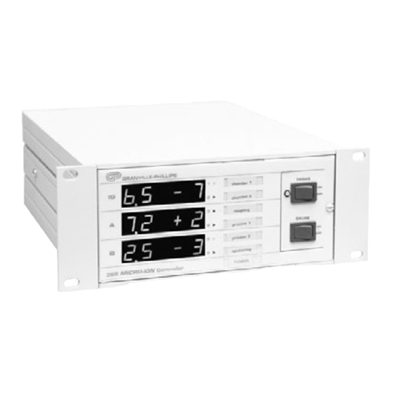
Granville-Phillips 358 Series Installation, Operation And Maintenance Instructions (100 pages)
Vacuum Measurement System
Brand:
Granville-Phillips
| Category:
Measuring Instruments
| Size: 1 MB
Table of Contents
Table of Contents
3
Safety
7
Safety Instructions
7
Certification
11
FCC Verification
11
Service Guidelines
11
Warranty Information
11
Chapter 1 System Components
13
System Components
13
Controller Front Panel
14
Controls Inside Front Panel
15
Top View of Controller (Cover Removed)
16
Options
17
Or RS-485/422 Computer Interface Module
17
Process Control Relay
17
Rear Panel with RS-232 Option
17
Specifications
18
IG Cables
19
Mounting Options
19
Power On/Off
19
Remote Input/Output
19
System Specifications
20
Dimensions
22
Controller
22
Convectron Gauge with Connector
23
Fittings
23
Micro-Ion Gauge with Connector
23
Catalog Number Configurations
24
Chapter 2 Initial Setup Procedures
25
Controller Setup
25
Top Cover Removal
25
Pressure Units Setup
26
Changing Units of Measure for the Electrometer Module
26
Changing the Display Update Rate on Electrometer Module
27
Overpressure Shutdown Adjustment
27
Changing Units of Measure for the Convectron Gauge
28
Display Update Rate Switch on Convectron Module
28
Process Control Setup
28
Developing a Logic Diagram of Control Logic
29
Process Control Channel Identification Windows
29
Ion Gauge Assignment for Process Control
31
Relay Polarity Setting
32
Process Control Tips
33
Computer Interface Setup
33
Connector Pinouts for the Rs-232 Computer Interface
34
Selecting the Byte Format for RS-232 Module
34
Baud Rate for RS-232 Module
34
Character Framing for RS-232 Module
35
Table
35
Handshake Line Control Switches for RS-232 Module
36
Talk-Only Mode for RS-232 Module
35
Clear to Send (CTS)
36
Data Carrier Detect (DCD)
36
Invert RTS Switch for RS-232 Module
37
Data Set Ready (DSR)
36
Table
37
Computer Interface Setup
38
Connector Pinouts for the RS-485 Computer Interface
38
Address
39
Character Framing for the RS-485 Computer Interface
40
Off off on
40
Off on off
40
Off on on
40
On off off 1200
40
On off on 2400
40
On on off 4800
40
On* On* On* 9600
40
Response Delay for the RS-485 Computer Interface
40
Selecting the Byte Format for RS-485 Module
40
Figure
41
Replacing Controller Cover
41
Chapter 3 Installation
43
Gauge Installation Tips
43
Cable Installation Statement
43
EMC Compliance
43
Environmental Conditions
44
Controller Installation
44
Installation Hardware Part Numbers
44
Installing the Controller
44
Figure
45
Mounting Configurations
45
Fuse Replacement Instructions
46
Line Voltage
46
Convectron Gauge Installation
47
1/8 NPT Mount
48
Compression Mount/Quick Connect
48
Conflat Flange Mount
48
Mounting Options
48
NW10KF, NW16KF, NW25KF and NW40KF Flange Mount
48
VCR ® /VCO ® Mount
48
Grounding the System
49
System Ground Test Procedure
49
Procedure for Testing Grounding of Systems
50
Connecting Analog Outputs
51
Electrometer Module Analog Output Signal
51
Convectron Gauge Analog Output Signal
52
Connecting Process Control Relays
53
Connecting the RS-232 Computer Interface
54
Command Summary
54
Reversing the Polarity of RTS
54
Connecting the RS-485 Computer Interface
55
Chapter 4 Preparing for Operation
57
Preparing for Pressure Measurement
57
Alternate ON/OFF Gauge Control
58
Micro-Ion Analog Output Signal
58
Preparing for Convectron Gauge Operation
59
Understanding Pressure Measurement in Gases Other than Nitrogen (or Air)
60
Examples
62
Ionization Gauge Auto Turn On/Off
69
Filament Auto Turn-On
69
Adjustment of Convectron Gauge Zero and Atmospheric Pressure Indications
70
Convectron Gauge Analog Output Signal
71
Preparing for Process Control Operation
72
Manual Override
72
Setpoint Display and Adjustment
72
To Display a Setpoint
72
To Modify a Setpoint
73
Preparing for Use of the RS-232 Computer Interface
73
Command Syntax for the RS-232 Computer Interface
73
Preparing for Use of the RS-485 Computer Interface
75
Command Syntax for the RS-485 Computer Interface
76
Chapter 5 Operation
79
Operation of the Series 358 Micro-Ion Vacuum Measurement System
79
Degas On/Off
79
Torr
79
Turning on the Controller
79
Operation of Micro-Ion Gauge Electrometer Module
82
Displaying Sensitivity with the Calibration Switch
82
Emission Range Switch
82
Relative Gas Sensitivities
82
Sensitivity Adjustment
82
Filament Select Switch
83
Filament Selection for the Micro-Ion Gauge Electrometer Module
83
Theory of Operation
84
Micro-Ion Gauge Theory of Operation
84
Convectron Gauge Theory of Operation
85
Microcontrollers and Bus Structure
85
Process Control Specifications
86
Process Control Theory of Operation
86
Chapter 6 Service and Maintenance
87
Service Guidelines
87
Damage Requiring Service
88
Overpressure Shutdown
90
Troubleshooting the Convectron Gauge Module
91
Convectron Gauge Test Procedure
91
Cleaning Contaminated Convectron Gauges
92
Process Control Troubleshooting
92
Troubleshooting
93
Field Installation of Modules
95
Service Form
96
Index
100
Advertisement
Advertisement
Related Products
Granville-Phillips Series 354
Granville-Phillips Micro-Ion 354 E Series
Granville-Phillips Micro-Ion 354010E-YD-T
Granville-Phillips Micro-Ion 354001E-YD-T
Granville-Phillips 352001
Granville-Phillips 352016
Granville-Phillips 352017
Granville-Phillips 352018
Granville-Phillips 352019
Granville-Phillips 350 Series
Granville-Phillips Categories
Controller
Measuring Instruments
Control Unit
Vacuum Cleaner
Laboratory Equipment
More Granville-Phillips Manuals
Login
Sign In
OR
Sign in with Facebook
Sign in with Google
Upload manual
Upload from disk
Upload from URL