
Related Manuals for Granville-Phillips Mini-Convectron 275 Series


Summary of Contents for Granville-Phillips Mini-Convectron 275 Series
- Page 1 Series 275 Mini-Convectron Vacuum ® Gauge Module with DeviceNet Digital Interface ® GRANVILLE-PHILLIPS ® Installation, Operation and Service Instructions...
- Page 3 1–303–652–2844 Email: co-csr@brooks.com © 2003, 2006, Brooks Automation. All rights reserved. Granville-Phillips, Micro Ion, Conductron, Convectron, and Stabil-Ion are registered trademarks of Brooks Automation. All other trademarks and registered trademarks are the properties of their respective owners. Installation, Operation, and Maintenance Instructions...
-
Page 5: Table Of Contents
Table of Contents Chapter 1 Before You Begin ......... Receiving Inspection . - Page 6 Table of Contents Chapter 4 Installation, Configuration ........Introdution .
- Page 7 Table of Contents Tables Table 3-1 Vacuum Connection Height Dimensions ... . . Table 3-2 Performance Specifications ..... . . Table 3-3 Physical Specifications .
- Page 8 ® ® Mini-Convectron Module with DeviceNet Digital Interface...
- Page 9 Certification Granville-Phillips certifies that this product met its published specifications at the time of shipment from the factory. Granville-Phillips further certifies that its calibration measurements are traceable to the National Institute of Standards and Technology to the extent allowed by the Institute’s calibration facility.
- Page 10 Granville-Phillips will supply return packaging materials at no charge upon request. This equipment has been tested and found to comply with the limits for a FCC Verification Class A digital device, pursuant to Part 15 of the FCC Rules.
- Page 11 Chapter 2 Safety WARNING Read this instruction manual before installation, using, or servicing this equipment. If you have any doubts about how to use this equipment safely, phone customer service at 1–303–652–4400 or 1–800–776–6543. These symbols are associated with the handling of poisons and acids. Follow all local and state codes when working with caustic materials and liquids.
- Page 12 Granville-Phillips equipment. Refer to Safety Instructions and Chapter 4, for additional information. If you have questions, or wish additional labels or literature, please contact one of our service personnel.
-
Page 13: General Description
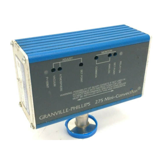
Chapter 3 Introduction General Description The Model 275 Mini-Convectron Vacuum Gauge Module, shown in Figure 3-1, is a modular instrument that is capable of measuring vacuum pressures from less than 1 x 10 Torr to 1000 Torr N equivalent (or air). The 275 Mini-Convectron Vacuum Gauge Module does not have external controls or adjustments and is available in RS-485 and DeviceNet digital interface and analog versions. -
Page 14: Specifications
Chapter 3 Specifications Figure 3-1 Dimensions 4.3 in 0.07 in 1.6 in (40.64 mm) (17.78 mm) (109.2 mm) RELAY ON S.P.1 S.P.2 PROCESS CONTROL TORR CONNECTOR 2.5 in mTORR COMMUNICATIONS CONNECTOR (63.5 mm) CALIBRATED FOR N Refer to Table 1-1 2.2 in (55.88 mm) Table 3-1... -
Page 15: Table 3-2 Performance Specifications
Introduction Refer to Table 3-2 and Table 3-3 for performance and physical specifications of the 275 Mini-Convectron Vacuum Gauge. Table 3-2 Performance Specifications Parameter Specification Measurement Range 1 x 10 to 1000 Torr for N or air. Operating Voltage and +24 VDC, nominal, 0.2 Amperes, 5 Watts maximum. -
Page 16: Power Supply Requirements
Chapter 3 Power Supply The customer supplied power supply should provide operating voltage and Requirements current to the 275 Mini-Convectron Vacuum Gauge Module as specified in Table 3-4. Surge current is the maximum momentary current when power is first applied. Operating current is the steady-state current during normal operation. -
Page 17: Component Description
Introduction Component The front, rear and side panels of the 275 Mini-Convectron Vacuum Gauge Description Module are shown in Figure 3-2 and described in the following paragraphs. Figure 3-2 275 Mini-Convectron Vacuum Gauge Module End Plate RELAY ON S.P.1 S.P.2 PROCESS CONTROL TORR CONNECTOR... -
Page 18: Front Panel
Chapter 3 Front Panel Digital Display The 7-segment digital display on the side of the 275 Mini-Convectron Module provides a viewable pressure reading. Pressure can be displayed in Torr or mTorr. The two LEDs next to the display indicate whether the pressure reading is in Torr or mTorr. -
Page 19: Rear Panel
Introduction Rear Panel Data Rate Switch The Data Rate Switches select the rate at which data is sent and received on the DeviceNet network. When the 275 Mini-Convectron Vacuum Gauge Module power is turned ON or reset by the network, the data rate switch position will be read by the gauge firmware. -
Page 20: Mounting Flange
Chapter 3 Table 3-7 DeviceNet Network (NET) LED States Network State LED State Description Not Powered, Not On- Module is not on-line Line • The module has not completed the DUP_MAC_ID test yet. • The module may not be powered, look at module status LED. Self Test Flashing Module is in self-test. -
Page 21: Theory Of Operation
Introduction Theory of Operation The transducer is a convection enhanced Pirani gauge providing rapid response, six decades of pressure transduction, stable calibration and good accuracy. The R1 Pirani sensing element shown in Figure 3-5, is one leg of a Wheatsone Bridge. Figure 3-5 Gauge Tube Schematic PIN 1... - Page 22 ® ® Mini-Convectron Module with DeviceNet Digital Interface...
-
Page 23: Chapter 4 Installation, Configuration
Chapter 4 Installation, Configuration Introdution This chapter provides you with the information required to install the 275 Mini-Convectron Vacuum Gauge Module. The flowchart in Figure 4-1 highlights the major tasks for installing the 275 Mini-Convectron Vacuum Gauge Module (with DeviceNet digital interface) and refers to the appropriate installation procedures within this section. - Page 24 Chapter 4 7. Do not mount the 275 Mini-Convectron Vacuum Gauge in a manner such that the deposition of process vapors, upon the internal surfaces of the gauge tube, may occur through line-of-sight access to the interior of the gauge tube. 8.
-
Page 25: Figure 4-1 275 Mini-Convectron Vacuum Gauge Module Installation (Devicenet Digital Interface)
Installation, Configuration Figure 4-1 275 Mini-Convectron Vacuum Gauge Module Installation (DeviceNet Digital Interface) START Install 275 Mini-Convectron Vacuum Gauge Module on Vacuum Chamber (Refer to Page 18) Install Trip Point Cable (Refer to Page 19) Connect DeviceNet network cable to the 275 Mini-Convectron Vacuum Gauge Module (Refer to Page 20) -
Page 26: Installation
Chapter 4 Installation CAUTION Reasonable care should be taken to install the 275 Mini-Convectron Vacuum Gauge Module where it is protected from physical damage. Compression Mount The 275 Mini-Convectron Vacuum Gauge is designed to fit a standard 1/2 inch compression (quick-disconnect) mount. WARNING A compression mount should not be used in positive pressure applications. -
Page 27: Other Mounts
Installation, Configuration Other Mounts Follow standard installation procedures for all other mount types. WARNING If an NW type flange is being used, ground the 275 Mini-Convectron Vacuum Gauge Module to the vacuum chamber by installing a metal flange clamp. Trip Point Cable 1. -
Page 28: Devicenet Digital Interface Installation
Chapter 4 DeviceNet Digital Use the following procedure to install the 275 Mini-Convectron Vacuum Interface Gauge (with DeviceNet digital interface) on the vacuum system and obtain Installation a vacuum chamber pressure. 1. Set the MAC ID switches on the 275 Mini-Convectron Vacuum Gauge Module to the correct address position for the vacuum chamber on which it is installed. -
Page 29: Configuring Polled I/O Data Format
Installation, Configuration Configuring Polled The 275 Mini-Convectron Vacuum Gauge Module can input data to the I/O Data Format network in two data types and status information can be included. The default format inputs one byte of status data and floating point pressure. See Table 5-5 on Page 35 for status bit definitions. -
Page 30: Table 4-6 Configuring Trip Point Relays
Chapter 4 Table 4-6 Configuring Trip Point Relays Parameter Service Class Instance Attribute Data Disable Trip Point Relay 1 Normal Polarity Trip Point 1 Reversed Polarity Trip Point 1 Trip Point Pressure 00 00 AF 43 Trip Point 1 350 Torr Set Trip Point 1 CD CC 4C 3E Hysteresis... -
Page 31: Checking Module Status
Installation, Configuration Checking Module Check the status if the 275 Mini-Convectron Vacuum Gauge Module will not Status read pressure due to a fault (alarm). Table 4-7 Checking 275 Mini-Convectron Vacuum Gauge Module Status Parameter Service Class Instance Attribute Data Check Status Unsigned integer, 1 byte* * Refer to the Series Mini-Convectron and MICRO-ION Vacuum Gauge Module DeviceNet Programmers Guide, P/N 354022, for... -
Page 32: Atmospheric Adjustment
Chapter 4 Atmospheric 1. Allow the chamber pressure to rise to atmospheric pressure. Adjustment 2. Use Table 4-10 to determine the atmospheric pressure (Torr) for your altitude and enter the data value for the Atmospheric Adjust Service. Table 4-10 Atmospheric Adjustment Parameters Altitude Above Sea Level (feet) Air or N Pressure (Torr) -
Page 33: Table 4-13 Uint Counts Versus Pressure
Installation, Configuration Use Table 4-13 to convert UINT counts to pressure. The counts are proportional to voltage and non-linear with respect to pressure. Table 4-13 UINT Counts versus Pressure Pressure UINT Count Pressure UINT Count 0.0001 5490 0.001 5986 0.01 6246 0.015 6523... -
Page 34: Use With Gases Other Than N Or Air
Chapter 4 Use with Gases other than N or Air WARNING Do not use the gauge tube to measure the pressure of combustible gas mixtures. The sensing element normally operates at only 125º C but it is possible that momentary transients or controller malfunction can raise the sensor above the ignition temperature of combustible mixtures which may explode causing injury to personnel or equipment damage. -
Page 35: Example 1 - Maximum Safe Indicated Pressure
Installation, Configuration Example 1 – Maximum Safe Indicated Pressure Assume a certain system will withstand an internal pressure of 1000 Torr or 19.3 psia. For safety, you wish to limit the maximum internal pressure to 760 Torr during backfilling. Assume you wish to measure the pressure of Argon (Ar). -
Page 36: Figure 4-2 Gas Pressures, 1 X
Chapter 4 –4 Figure 4-2 Gas Pressures, 1 x 10 to 1 Torr Convectron gauge axis must be horizontal Pressure unit equivalents: 1 µm Hg = 1 mTorr = 1 x 10 –3 Torr 1000 µm Hg = 1 Torr Indicated pressure in Torr (Nitrogen equivalent) ®... -
Page 37: Figure 4-3 Gas Pressures, 1 X
Installation, Configuration –2 Figure 4-3 Gas Pressures, 1 x 10 to 1000 Torr, First Gas Set Convectron gauge axis must be horizontal Pressure unit equivalents: 1 µm Hg = 1 mTorr = 1 x 10 –3 Torr 1000 µm Hg = 1 Torr Indicated pressure in Torr (Nitrogen equivalent) ®... -
Page 38: Figure 4-4 Gas Pressures, 1 X
Chapter 4 –2 Figure 4-4 Gas Pressures, 1 x 10 to 1000 Torr, Second Gas Set Convectron gauge axis must be horizontal Pressure unit equivalents: 1 µm Hg = 1 mTorr = 1 x 10 –3 Torr 1000 µm Hg = 1 Torr Indicated pressure in Torr (Nitrogen equivalent) ®... -
Page 39: Vacuum Gauge Module Process Chamber Baking
Installation, Configuration 4.10 Vacuum Gauge The 275 Mini-Convectron Vacuum Gauge tube can be removed from the Module Process module electronics without interrupting the vacuum within the process Chamber Baking chamber. CAUTION The temperature of the 275 Mini-Convectron Vacuum Gauge Module electronics cannot exceed 85º... -
Page 40: Figure 4-5 Module Removal For Baking The Process Chamber
Chapter 4 Figure 4-5 Module Removal for Baking the Process Chamber ® ® Mini-Convectron Module with DeviceNet Digital Interface... -
Page 41: Chapter 5 Troubleshooting
Chapter 5 Troubleshooting Introduction The problems presented in Table 5-1 are followed by possible causes and corrective actions. Troubleshooting Procedures Table 5-1 DeviceNet Digital Interface Troubleshooting Procedures Problem Possible Cause Corrective Action No Power Indication No input power. Verify that there is + Correct reason for lack of power. -
Page 42: Status Information
Chapter 5 Table 5-1 DeviceNet Digital Interface Troubleshooting Procedures (Continued) Problem Possible Cause Corrective Action Readout cannot be calibrated to the 1. Gauge incorrectly calibrated out of 1. Use restore factory calibration specified value using Zero_Adjust or operating range. command (Service 32 , Class Gain_Adjust service. -
Page 43: Table 5-4 Identity Object Status, Class 1, Instance 1, Attribute 5
Troubleshooting Table 5-4 Identity Object Status, Class 1, Instance 1, Attribute 5 Definition An object is allocated, unrelated to error condition Configured, unrelated to error condition Minor recoverable fault, same as bit 3, Analog Sensor Status Major unrecoverable fault, same as bit 1, Analog Sensor Status Table 5-5 I/O Status Byte and Device Supervisor Exception Status, Class 30... - Page 44 ® ® Mini-Convectron Module with DeviceNet Digital Interface...
-
Page 45: Chapter 6 Service
Chapter 6 Service Introduction The procedures in this section provide instructions for normal service issues that may be required during use of the 275 Mini-Convectron Vacuum Gauge Module. Phone customer service at 1–303–652–4400 or 1–800–776–6543 if there are questions pertaining to the service of the 275 Mini-Convectron Vacuum Gauge Module. -
Page 46: Figure 6-1 Gauge Tube Removal From Module
Chapter 6 Figure 6-1 Gauge Tube Removal from Module ® ® Mini-Convectron Module with DeviceNet Digital Interface... -
Page 47: Figure 6-2 Adding And Draining Solvent
Service 4. Hold the PC board/gauge tube assembly and carefully remove the gauge tube from the tube socket in the direction of the arrow shown in Figure 6-1. 5. Hold the gauge tube with body at a 45º angle as shown in Figure 6-2. CAUTION Do not shake the gauge tube while the solvent is in the tube. -
Page 48: Mini-Convectron Gauge Tube Test And Replacement
Chapter 6 Mini-Convectron This procedure can be used to test and/or replace the gauge tube if you Gauge Tube Test and suspect it has failed. Replacement WARNING To prevent electrical shock, shut down electrical power before servicing the 275 Mini-Convectron Vacuum Gauge Module. Do not touch any gauge pins while the gauge tube is under vacuum or connected to a controller. - Page 49 Service 6. If any of the resistance values in Table 6-1 are not within specification, the gauge tube should be replaced. 7. Phone customer service at 1–303–652–4400 or 1–800–776–6543 to order a new gauge tube. 8. Hold the PC board/gauge tube assembly and carefully push the end of the replacement gauge tube into the tube socket until it stops.
- Page 50 Street address _______________________________________________________________________________ City _________________________________________ State _________________ ZIP __________________ Please help Granville-Phillips provide the best possible service by giving us information that will help us determine the cause of the problem and protect our analysis and calibration equipment from contamination.
- Page 52 Series 275 Mini-Convectron Vacuum ® Gauge Module with DeviceNet Digital Interface ® GRANVILLE-PHILLIPS ® 6450 Dry Creek Parkway Longmont, CO, U.S.A. 80503 Phone 303–652–4400 15 Elizabeth Drive Chelmsford, MA, U.S.A. 01824 Phone 978–262–2400 To obtain a copy of this instruction manual online, visit our website at www.brooks.com...
Need help?
Do you have a question about the Mini-Convectron 275 Series and is the answer not in the manual?
Questions and answers