Table of Contents
Advertisement
Quick Links
Advertisement
Table of Contents

Subscribe to Our Youtube Channel
Related Manuals for Apollo RIGHT ARM 3

Summary of Contents for Apollo RIGHT ARM 3
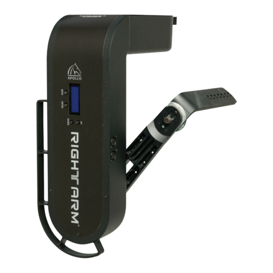
- Page 1 RIGHT ARM ® Pan and Tilt System...
-
Page 3: Table Of Contents
1 – Pipe Clamp 1 – M-16 x 30 Hex-head Bolt with 1 Flat and 1 Lock Washer 2 – Safety Cables 1 – User Manual Optional Parts: See the RightArm at ApolloDesign.net ® Apollo Design Technology, Inc. 260.497.9191 • ApolloDesign.net... -
Page 4: Introduction
Introduction Since 1992, Apollo Design Technology, Inc. has been one of the world’s leading innovators, manufacturers and distributors of gobos, color filters, lights and related equipment and accessories for the lighting industry. We are continually engineering new products to help you create and execute the designs of your dreams for theaters, bands, advertising, touring companies, television, motion pictures, museums, retail and architecture. -
Page 5: Safety
• The Right Arm is not intended for residential use. ® • Safety cables must be used when installing the Right Arm . Apollo is not ® responsible for damage or injury resulting from improper use of safety cables. Apollo Design Technology, Inc. -
Page 6: Compatible Fixtures
• Snow Machines • PAR Fixtures • Projectors • Ellipsoidal Fixtures • Video Cameras • Fresnel Fixtures CAUTION! The Right Arm is designed for use with fixtures that do not ® exceed 40 lbs. Apollo Design Technology, Inc. 260.497.9191 • ApolloDesign.net... -
Page 7: Installation
This cable is used to power ® devices attached to the Right Arm . This cable has 16 gauge conductors and can ® be plugged into a dimmed or non-dimmed source to power fixtures up to 15 amps. Apollo Design Technology, Inc. 260.497.9191 • ApolloDesign.net... -
Page 8: Hang The Right Arm
WARNING! Securely tighten bolt that fastens the clamp to the Right Arm . Use the safety cable provided to prevent the unit ® from falling in the event the hanging clamps or brackets fail. Apollo Design Technology, Inc. 260.497.9191 • ApolloDesign.net... -
Page 9: Attach A Fixture
• Connect the lamp power cable to the wire that exits at the tilt shaft. • Secure the lamp power cable so it does not interfere with the tilt motion. Holes to Attach Fixture on Tilt Arm. Apollo Design Technology, Inc. 260.497.9191 • ApolloDesign.net... -
Page 10: Balance The Fixture
Fixture Yoke Tilt same height as the tilt bolt. Tilt Axis Height Tilt Axis Adjustment Bolt ETC Source Four Ellipsoidal ETC Yoke Measures 9 ⁄ " Adjust Tilt Arm to 9 ⁄ " Apollo Design Technology, Inc. 260.497.9191 • ApolloDesign.net... - Page 11 Use approved safety cables and mounting methods to secure these devices. Install safety cables in such a way as to not inhibit the movement of the Right Arm ® Apollo Design Technology, Inc. 260.497.9191 • ApolloDesign.net...
-
Page 12: Data Cable
22 AWG. Length 1,000' Maximum DMX Receiving Devices per Line 32 Maximum Termination 120W Resistor (Last DMX device on the line.) Data In Connector XLR 5-pin Male Data Out Connector XLR 5-pin Female Apollo Design Technology, Inc. 260.497.9191 • ApolloDesign.net... -
Page 13: Operation
❱ ### Pan Range • ###° (10° to 300°) Tilt Range • ###° (10° to 270°) Pan And Tilt Range Test Factory Defaults • Confirm? • Demo Mode • Recalibrate Motors Both Tilt Apollo Design Technology, Inc. 260.497.9191 • ApolloDesign.net... -
Page 14: Channel Assignments And Reset Channel
, other DMX devices will not be affected. ® Loss of DMX If the DMX data to the Right Arm is lost, the unit will hold the last position. ® When the DMX signal is restored, normal operation will resume. Apollo Design Technology, Inc. 260.497.9191 • ApolloDesign.net... -
Page 15: Dmx Output And 24Vdc/Data Accessory Output
• If no DMX signal is present, the Right Arm will move to the home position of 0% ® tilt and 50% pan. • The Right Arm will wait in this position until DMX information is received. ® Apollo Design Technology, Inc. 260.497.9191 • ApolloDesign.net... -
Page 16: Specifications
Material / Color Aluminum, Black or White Textured Matte Powder Coat. Custom Colors Available. Ports XLR 5-pin Female and XLR 5-pin Male Safety Cable Continued Product specifications shown are subject to change without notice. Apollo Design Technology, Inc. 260.497.9191 • ApolloDesign.net... - Page 17 Pin 1: 0 Volts DC (14 Gauge) Pin 2: Negative Data (22 Gauge) Pin 3: Positive Data (22 Gauge) Pin 4: Positive 24 Volts DC (14 Gauge) Chassis: Ground Bounding (24 Gauge) Apollo Design Technology, Inc. 260.497.9191 • ApolloDesign.net...
-
Page 18: Warranty
• Products being returned for warranty repair must display the original serial number. Removal of the serial number voids the product’s limited warranty. • Despite the care taken for the compilation of this manual, Apollo Design Technology, Inc. cannot be held responsible for any damages resulting from errors that may appear in this manual. - Page 20 RIGHT ARM ® Pan and Tilt System Apollo Design Technology, Inc. 260.497.9191 ApolloDesign.net © Copyright 2015 Apollo Design Technology, Inc. 11/15...
Need help?
Do you have a question about the RIGHT ARM 3 and is the answer not in the manual?
Questions and answers