
Subscribe to Our Youtube Channel
Summary of Contents for UNISource Corporation FG-8102
- Page 1 Operation Manual FG-8102 2MHz Function Generator FG-8103 3MHz Function Generator FG-8105 5MHz Function Generator FG-8110 10MHz Function Generator UNISOURCE CORPORATION...
- Page 2 WARRANTY Warranty service covers a period of one year from the date of original purchase. In case of technical failure within one year, our service center or sales outlet free of charge will provide repair service. We charge customers for repair after the one-year warranty period has been expired.
- Page 3 Introduction Thank you for purchasing our product.Electronic measuring instruments produced by us are high technology products made under strict quality control. We guarantee their exceptional precision and utmost reliability. For proper use of the product, please read this operation manual carefully. Note 1.
- Page 4 Safety Symbols Protective earth (ground) To identify any terminal which is intended for connection to An extemal conductor for protection against electric shock In case of a fault, or the terminal of a protective earth (ground) electrode. Functional earth terminal on the rear panel. “IN”...
-
Page 5: Table Of Contents
CONTENTS 1. PRODUCT DESCRIPTION 1-1. Introduction ----------------------------------------------------------------- ( 1-2. Technical Specifications ------------------------------------------------- ( 1-3. Equipment Ratings -------------------------------------------------------- ( 1-4. Supplied Accessories ---------------------------------------------------- ( 2. INSTALLATION 2-1. Initial Inspection ----------------------------------------------------------- ( 2-2. Connecting Ac Power ---------------------------------------------------- ( 2-3. Cooling And Ventilation -------------------------------------------------- ( 2-4. -
Page 6: Product Description
VCF(voltage controlled frequency) produces precision sine, square and triangle waves over the 0.02 Hz to 10 MHz (FG-8102; 0.02Hz to 2MHz, FG-8103: 0.03Hz to 3MHz, FG-8105; 0.05Hz to 5MHz, FG-8110; 0.1Hz to 10MHz) for sub-audible, audio, ultrasonic and RF applications. A continuously variable DC offset allows the output to be injected directly into circuits at the correct bias level. - Page 7 WAVEFORM CHARACTERISTICS Sine wave -Flatness : ± 3dB to 2 MHz(8102), 3 MHz(8103), 5MHz(8105), 10MHz(8110) -Distortion : Less than 1% at 0.2 Hz to 100 KHz Square wave -Rise and Fall Time : Less than 120 nS Triangle wave -Linearity : More than 99% at 0.2 Hz to 100 KHz TTL Output -Rise and Fall time : Less than 25 nS...
-
Page 8: Equipment Ratings
1-3. Equipment Ratings Power & Fuse Ratings Input Voltage Fuse Power Max. 115VAC +/-10%, 50/60Hz F 0.5A 250V F 0.2A 250V (8102/8103) 230VAC +/-10% , 50/60Hz F 0.25A 250V (8105/8110) NOTE: AC Power is preset to 115V or 230V in factory according to the request of customer. -
Page 9: Installation
2. INSTALLATION 2-1. Initial Inspection This instrument was carefully inspected both mechanically and electrically before shipment. It should be physically free of damage. To confirm this, the instrument should be inspected for physical damage in transit. Also, check for supplied accessories are present and correct. -
Page 10: Operation
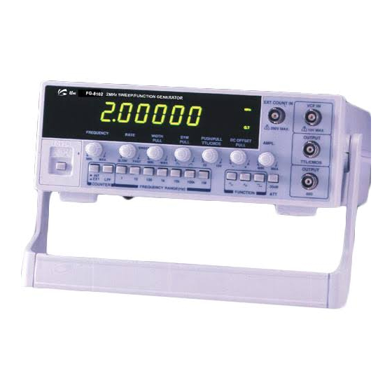
3. OPERATION 3-1. Controls, indicators and connectors 15 19 FIG 1-1. FRONT PANEL OPERATOR’S CONTROLS(8102,8103) FIG 1-2. FRONT PANEL OPERATOR’S CONTROLS(8105,8110) - Page 11 LED DISPLAY. Displays Internal or External Frequency. INTERNAL/EXTERNAL SWITCH. PUSH IN : External Frequency Counter. PUSH OUT: Internal Frequency Counter. RANGE SWITCHES. Frequency Range Selector. FUNCTION SWITCHES. Select Sine wave, Triangle Wave Or Square Wave Output. ATTENUATOR. Selects Output Level By -20 dB. GATE TIME INDICATOR.
-
Page 12: Operating Instruction
TILT STAND. Pull Out to Adjust Tilt. POWER SWITCH. Push type switch. turning on the power when pressed. LOW PASS FILTER VOLTAGE FUSE POWER MAX 115V ~ 0.5A F 230V ~ 0.2A F S/N : Made in Korea FIG 2-1. REAR PANEL(8102,8103) VOLTAGE FUSE POWER MAX... -
Page 13: Use As Function Generator
Range switch setting of 1M produces 2 MHz output(2.0x1M = 2M). E. And also it can display the desired frequency by 6 digit LED display FG-8102/FG-8103 – 7digit LED display for FG-8105/FG-8110. F. Select sine, square, or triangle wave output by pressing the corresponding FUNCTION button. - Page 14 H. Adjust the 50Ω output to the desired amplitude with the AMPLITUDE control. TTL Pulse 0V Triangle 0V Sine Square FIG. 3 OUTPUT WAVEFORMS AND PHASE RELATIONSHIPS I. A positive or negative DC component can be added to the signal at the 50Ω BNC by use of the DC OFFSET control, as required by the circuit into which the signal is being injected.
- Page 15 desired combination is obtained without clipping. Keeping the Amplitude control in the lower half of its adjustment range reduces the probability of clipping. B. To set the DC offset to zero or a specific DC voltage, depress the Function Switches slightly so that all switches are released(all buttons out). This removes signal from the output and leaves the DC only.
-
Page 16: Use As Pulse Generator
constant terminating impedance may be maintained while injecting signal into moderate and high impedance circuits(500Ω and up)by adding a coaxial tee in the output cable and connecting a 50Ω termination to one leg. Remove the 50Ω termination when injecting into a 50Ω circuit. Also keep DC injection point, the DC offset should be set to match the circuit voltage, or blocking capacitor may be required to avoid DC loading with 50Ω. - Page 17 Adjust Period Of Shorter Duration With Freq. Controls Pulse (Square) Ramp (Triangle) Skewed (Sine) Adjust Period Of Longer Duration With SYNC Symmetry Controls FIG 5. PULSE, RAMP, AND SKEWED SINE WAVE GENERATION C. If both a specific pulse width and repetition rate (specific rise time and fall time for ramp wave), :are required, The waveform may be obtained as follows: a.
-
Page 18: Ttl/Cmos Output
DESIRED FREQUENCY = DESIRED PULSE WIDTH x 2 3-5-1. TTL/CMOS OUTPUT(FG-8102/FG-8103 only) TTL/CMOS output is specifically designed for compatibility with TTL/CMOS digital logic circuits. Set-up time is considerably reduced because the fixed logic levels and polarity are ready for direct injection into TTL/CMOS circuits. there is a need for protection from accidental Application of too high amplitude or incorrect DC offset which might damage semiconductors. -
Page 19: Ttl/Sync Output
A. Using the square wave generator or pulse generator modes, clock pulses can be generated for testing, troubleshooting or circuit analysis. The instrument could even be used as a substitute master clock generator as TTL/CMOS circuits can be driven from the TTL/CMOS BNC. B. - Page 20 2) Considerations A. The approximate frequency deviation for a given VCF IN signal can be determined as follows, The 0.1 V change at the VCF IN BNC produces a frequency change of 1% of the highest frequency obtainable on a given range.
-
Page 21: External Control Of Vcf
3-7. External Control Of VCF Within a given range, the FREQ. dial setting normally controls the output frequency of generator. However, applying voltage at the VCF IN BNC on the front panel also may control it. There are three basic possible modes of external VCF control as detailed below, A. -
Page 22: Programmed Frequency Selection
C. The FREQ. dial is usually set to 0.02 when using external VCF control. This reduces the dialed VCF voltage to zero and allows the external VCF voltage to exercise complete control. It also reduces the effects of dial setting inaccuracy. -
Page 23: Use As Externally Controlled Sweep Generator
2) Considerations Minimum FREQ. dial setting is recommended for most sweep generator operation. The dial setting determines the lowest frequency of generator. The sweep generator will sweep upward from that point. However, it will sweep upward only to the range limit(highest frequency to which the dial can tune on the selected range). -
Page 24: Maintenance
decimal points display the max. 50 MHz of external frequency. E. PUSHED-IN FREQ.RANGE S.W X1. F. LOW PASS FILTER : If necessary, engage the LPF (low pass filter) switch. This route the input through a low pass filter (-3 dB point of approximately 100 KHz) before application to the frequency counter. -
Page 25: Fuse Replacement
4-1. Fuse replacement Disconnect and remove all connections from any live power source. Unscrew fuse holder by screw driver. Locate the defective fuse and remove it by gently pulling-out. Install a new fuse of the SAME SIZE AND RATING. Screwing fuse holder. CAUTION MAKE SURE THAT THE RATED AND SPECIFIED FUSES ARE USED FOR REPLACEMENT. -
Page 26: Troubleshooting By Signal Substitution
Inject the type of signal normally used by the equipment being tested. This instrument can generate almost any type of signal normally required in the frequency range (FG-8102:0.02Hz to 2MHz, FG-8103:0.03Hz to 3MHz, FG-8105: 0.05Hz to 5MHz, FG-8110: 0.1Hz to 10MHz). -
Page 27: Amplifier Overload Characteristics
5-4. Amplifier Overload Characteristics The overload point for some amplifiers is difficult to determine by using sinewave input. The triangle waveform is ideal for this type of test because any departure from absolute linearity is readily detectable. By using the triangle output, the peak overload condition for an amplifier can be readily determined. -
Page 28: Amplifier Performance Evaluation Using Square Waves
5-5. Amplifier Performance Evaluation Using Square Waves The standard sinewave frequency reopens curves do not give a full evaluation of the amplifier transient response. the square wave, because of the high harmonic content, yields much information regarding amplifier performance when used in conjunction with an oscilloscope. - Page 29 Dual Trace Oscilloscope Preferred Square Wave Selected...
- Page 30 FIG 7. AMPLIFIER PERFORMANCE EVALUATION USING SQUARE WAVES. A. Test Set-up B. Equivalent Circuit Of Test Set-Up GENERATOR C. Graph Of Results...
-
Page 31: Testing Speakers And Impedance Networks
FIG 8. TESTING SPEAKER SYSTEMS AND IMPEDANCE NETWORKS. 5-6. Testing Speakers and Impedance Networks This instrument can be used to provide information regarding the input impedance of a speaker or any other impedance network vs. frequency. In addition, the resonant frequency of the network can be determined. A. -
Page 32: Digital Frequency Selection
5-7. Digital Frequency Selection Frequencies can be switched electronically by using the set-up shown in FIG. 9. The preset voltages can be digitally selected and applied to the VCF IN BNC. Although provision for two frequencies are shown, additional frequencies can be added using redundant circuits. - Page 33 exercised from zero to full scale to observe defective deflection such as sticky meter movements. This is marking shown on the product or its literature, indicates that it should not be disposed with other household wastes at the end of its working life. To prevent possible harm to the environment or human health from uncontrolled waste disposal, please separate this from other types of wastes and recycle it responsibly to promote the sustainable reuse of material resources.
Need help?
Do you have a question about the FG-8102 and is the answer not in the manual?
Questions and answers