
Subscribe to Our Youtube Channel
Related Manuals for Wallenstein BXTR6438F


Summary of Contents for Wallenstein BXTR6438F
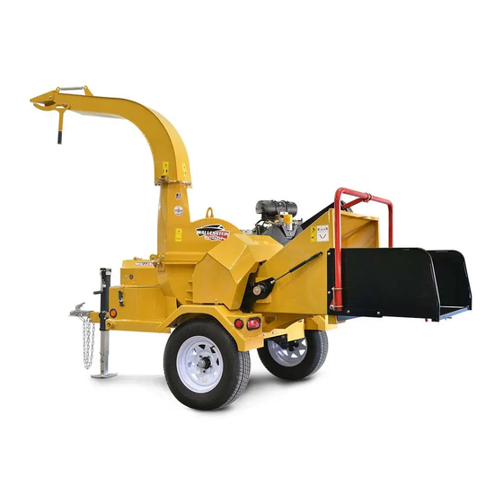
- Page 1 OPERATOR'S MANUAL Serial number 2E9US1111KS091353 and up BXTR 6438F / P Trailer Wood Chipper ™ TECHNOLOGY Rev Apr-2021 Document Number: Z97073_En...
-
Page 2: Foreword
W034 Review all safety, operation and maintenance information contained in this manual. Wallenstein Equipment Inc. • © 2021. All rights Safe, efficient and trouble-free operation of this reserved. Wallenstein product requires that anyone using or... -
Page 3: Table Of Contents
BXTR6438 Table of Contents 1. Foreword ..............2 5. Service and Maintenance ........42 1.1 Introduction ............2 5.1 Fluids and Lubricants ........42 1.2 Delivery Inspection Report ........4 5.2 Greasing ............42 1.3 Serial Number Location ........5 5.3 Service Illustration ..........43 1.4 Types of Decals on the Machine ......6 5.4 Service Record ..........45 5.5 Maintenance .............46 2. -
Page 4: Delivery Inspection Report
BXTR6438 1.2 Delivery Inspection Report Wallenstein BXTR6438 Trailer Wood Chipper To activate warranty, register your product at: www.wallensteinequipment.com This form must be filled out by the dealer at the time of delivery, then signed by the dealer and customer. The product manuals have been received by me... -
Page 5: Serial Number Location
Record Product Information Here BXTR6438 Model: Serial Number: 01264 Manufactured by: Wallenstein Equipment Inc., 7201 Line 86, Wallenstein ON N0B2S0, Canada MODEL: ########## TYPE OF VEHICLE/TYPE DE VEHICLE: TRA / REM GAWR/PNBE (KG): GVWR/PNBV (KG): DIMENSION- RIM/JANTE... -
Page 6: Types Of Decals On The Machine
They can be either vertical or horizontal. Product Decals indicate machine model and serial number, and other important information. Manufactured by: Wallenstein Equipment Inc., 7201 Line 86, Wallenstein ON N0B2S0, Canada MODEL: ########## TYPE OF VEHICLE/TYPE DE VEHICLE: TRA / REM GAWR/PNBE (KG):... -
Page 7: Safety
• Accidents Can Be Avoided DANGER – The policy of Wallenstein Equipment Inc. is to produce products that are safe and reliable. However, even Indicates an imminently hazardous situation that, when using well-engineered equipment, there is if not avoided, will result in death or serious injury. -
Page 8: Safety Rules
BXTR6438 2.4 Safety Rules • DO NOT allow riders during transport. • DO NOT risk injury or death by ignoring good safety • DO give operating instructions to operators or employees practices. before allowing them to operate the machine, and REVIEW annually thereafter. -
Page 9: Being Prepared
BXTR6438 There is no substitute for a cautious, safe-minded • Train all new personnel and review instruc tions frequently operator who recognizes potential hazards and follows with existing workers. Only properly trained and physically reasonable safety practices. This machine must be able operators should use this equipment. -
Page 10: Feed Roller Safety
BXTR6438 • Stop engine when leaving the machine unattended. • Before transporting, perform a walk-around inspection to ensure everything is safe. 2.9 Feed Roller Safety 2.11 Refueling Safety • Do not overreach into the hopper. Keep proper balance and footing at all times. •... -
Page 11: Hydraulic Safety
BXTR6438 • Avoid contact with battery electrolyte: • If injured by a concentrated high-pressure stream of hydraulic fluid, seek medical attention immediately. Serious • External Contact: Flush immediately with water. infection or toxic reaction can develop from hydraulic fluid • Eye Contact: Flush with water for 15 minutes. Get piercing the skin surface. - Page 12 BXTR6438 • DO NOT operate engine with an accumulation of grass, leaves, dirt or other combustible materials in the muffler area. • DO NOT use this engine on any forest covered, brush covered, or grass covered unimproved land unless a spark arrester is installed on the muffler.
-
Page 13: Sign-Off Form
BXTR6438 2.16 Sign-Off Form The design and manufacture of this product conforms to relative provisions in the following standards: Anyone using this machine must read and thoroughly ISO 4254-1 Agricultural machinery – Safety understand all Safety, Operation and Maintenance information in this manual. An untrained operator ASABE S318 Safety for Agricultural Field Equipment should never use this machine. -
Page 14: Safety Sign Explanations
BXTR6438 2.17 Safety Sign Explanations Practicing good safety means becoming familiar with The top (or left-hand) panel shows the safety alert (the safety signs and warnings and being aware of the potential hazard), and the bottom (or right-hand) panel situations that require alertness. shows the message (how to avoid the hazard). - Page 15 BXTR6438 Safety Signs Z94207 Z94120 Z94419 Z94203 7.0” 175mm Z94237 Z94120 Z94207...
- Page 16 BXTR6438 1. Caution! 4. Warning! Risk of injury from flying objects. Risk of explosion. Stay clear of material discharge Do not jump start / charge a chute. Machine can expel wood frozen battery. Frozen batteries chips fast enough to cause injury. can explode and result in serious 0°...
- Page 17 BXTR6438 7. Caution! 10. Caution! Risk of serious injury or death Risk of personal injury or if hands or limbs are caught in equipment damage. rotating parts. Do not put material larger than 7.0" Do not operate machine with out (175 mm) diameter into the chipper.
-
Page 18: Replacing Damaged Safety Signs
• Replacement safety signs are available from your authorized Distributor, Dealer Parts Department, or Wallenstein Equipment. Procedure 1. Be sure that the installation area is clean and dry. IMPORTANT! If parts are replaced that have 2. -
Page 19: Controls
BXTR6438 3. Controls Please review this section to familiarize yourself with the location and function of each control before starting. The BXTR6438 control panel is laid out so that the controls are easy to see and use. Familiarizing yourself with the controls will enable you to take advantage of all the features available on the BXTR6438 and apply them as conditions demand. -
Page 20: Machine Components
Major components of the BXTR6438 are illustrated here. Please review this section, many of the component descriptions here are used throughout the manual to explain function and safety. For a detailed parts breakdown, see your dealer or visit the Wallenstein website to download the BXTR6438 Parts Manual. Upper Rotor... -
Page 21: Discharge Chute
BXTR6438 3.4 Discharge Chute: The discharge chute is designed with a spring- Latch Handle loaded latch handle that allows the chute to be positioned 360° then locked into position with the latch. 1. Lift the latch handle till the chute lock pin disengages. -
Page 22: Roller Feed Control Bar
BXTR6438 3.5 Roller Feed Control Bar The feed roller control bar controls the forward, reverse and stop action of the feed rollers. IMPORTANT To quickly stop the feed rollers in an emergency situation, the bar can be rapidly pulled or pushed to its maximum position and will immediately stop the roll- ers. -
Page 23: P3 Pulse Electronic Control System
Navigating through the menus is done with the four soft keys below the display screen. Icons in the display The Wallenstein P3 PULSE Electronic Control System above the soft keys indicate menu selection options. optimizes the capacity of the chipper. Operators can... - Page 24 BXTR6438 3.6.3 User Interface 1. Display Screen The Display Screen is the user interface for the P3 PULSE Electronic Control System. The screen is an anti-glare coated, 4.3 in (109 mm) color display. The system is controlled by navigating through the soft key buttons. 2.
- Page 25 BXTR6438 3.6.4 Menus Main screen 0:00 HOURS FEED POSITION The Main screen is the default screen with the ignition NEUTRAL key in the ON position. Pressing the key below ROTOR SPEED 0000 Home icon in any sub menu takes you back to the Main screen.
- Page 26 BXTR6438 Settings screen Press the soft key button below the icon to access 0:00 HOURS FEED POSITION Settings. This is the main screen to set up all your NEUTRAL ROTOR SPEED 0000 machine parameters. All settings are retained when the machine is shut down. The Settings screen menu contains: •...
- Page 27 BXTR6438 Max Feed Speed MAX FEED SPEED FEED SETTINGS MAX FEED MIN FEED FEED START MIN ROTOR SPEED SPEED SPEED 0000 0000 Sets the maximum feed roller speed in 5% increments. The value is shown as a percentage of the maximum speed (100%).
- Page 28 BXTR6438 Reset Defaults screen P3 PULSE setup parameters can be returned to the SETTINGS FEED SETTINGS factory settings if desired. RESET DEFAULTS DIAGNOSTICS SELECT MACHINE ENTER PASSWORD • From the Settings screen, use the Up or Down arrows to navigate to Reset Defaults. •...
- Page 29 BXTR6438 Machine Select screen IMPORTANT! Machine model must be selected during initial setup before operating the machine. SETTINGS FEED SETTINGS RESET DEFAULTS DIAGNOSTICS SELECT MACHINE ENTER PASSWORD Machine Select must be done when the P3 PULSE is set up for the first time. Once you have selected your machine, P3 sets up the default settings for that model.
-
Page 30: Ball And Coupler
BXTR6438 3.7 Ball and Coupler 3.7.1 Coupling for transport Review the transport safety section (2.7) before proceeding. The Wood Chipper should always be located on a level, dry area that is free of debris and other foreign objects. When attaching the machine to a tow vehicle, follow this procedure: 6. -
Page 31: Operating Instructions
Important 4.2 To the New Operator or Owner Ensure all operators understand how to put the The Wallenstein Trailer Wood Chippers are designed machine in safe condition before working with this to chip and chop scrap lumber, small trees, brush, machine. -
Page 32: Pre-Operation Checklist
4.3 Pre-operation Checklist with all operating and safety procedures and following them. Efficient and safe operation of the Wallenstein Trailer Wood Chipper requires that each operator reads and Although the Trailer Wood Chipper is easy to use, understands the use procedures and all related safety each operator should review this section to familiarize precautions outlined in this section. -
Page 33: Machine Set-Up
BXTR6438 4.4 Machine Set-up Follow this procedure to prepare and set-up the machine at the work site: 1. Use the tow vehicle to position the Wood Chip- 4. Open the latch on the feed table and carefully per at the work site. lower the feed table. -
Page 34: Machine Break-In
BXTR6438 4.5 Machine Break-In 4.6 Engine Controls Refer to the Kohler® engine manual for further Although there are no operational restrictions on the explanation on engine controls. Wood Chipper when used for the first time, it is rec- ommended that the following mechanical items be checked: A. - Page 35 BXTR6438 4.6.1 Starting Procedure Choke Please review the engine controls section (4.5.1) and This left/right slider controls the engine owners manual for starting and stopping the position of the choke. the engine. Slide the choke to the right to close the choke for 1.
-
Page 36: Chipping Operation
BXTR6438 4.7 Chipping Operation The BXTR6438 Wood Chipper is a strong, rugged machine that is built to a straight-forward design which provides consistent chipping of logs up to 7" (177 mm) in diameter. Always wear personal protective equipment (PPE) whenever operating the machine. This includes but is not limited to a hard hat, protective shoes with slip re- sistant soles, protective goggles or face shield, heavy gloves, hearing protection and protective clothing. -
Page 37: Unplugging
BXTR6438 4.8 Unplugging: 7. Check that everyone is clear of machine before restarting engine. Although the machine is designed to handle a wide 8. Start the engine and resume working. variety of material without any problem, occasionally it may plug. If the machine plugs, follow this procedure to 4.8.1 Severe plug: unplug: 1. - Page 38 BXTR6438 10. Once the roller assembly is up, the gas springs will keep 15. Check that everyone is clear of machine before restarting the assembly up in position, and you will have access to engine. the roller housing. 16. Start the engine and resume working. 11.
-
Page 39: Refueling
BXTR6438 4.9 Refueling: BXTR6438 fuel tank holds 12 gal US (50 L) of fuel, and is located in front of the engine. Avoid running the tank dry. Use the appropriate grade of fuel, and use caution to prevent spilling. Do not smoke while Fuel Gauge refueling. -
Page 40: Transporting
BXTR6438 4.10 Transporting 4.10.1 Prepare for Transport: Follow these instructions: 8. Inspect and replace any axle dust caps that are damaged or leaking. 1. Stow feed table and secure the latch. 9. Turn the discharge hood and point toward the feed table to 2. -
Page 41: Storage
BXTR6438 4.11 Storage 5. Inspect all rotating parts for entangled mate- STORAGE SAFETY rial. Remove all entangled material. 6. Remove all remaining material and debris from the machine. • Store the chipper in an area away from hu- man activity. 7. -
Page 42: Service And Maintenance
BXTR6438 5. Service and Maintenance MAINTENANCE SAFETY 5.1 Fluids and Lubricants • Good maintenance is your responsibility. Poor maintenance is an invitation to trouble. 1. Grease: Use an SAE multipurpose high tem- perature grease with extreme pressure (EP) • Follow good shop practices. performance. -
Page 43: Service Illustration
BXTR6438 5.3 Service Illustration This illustration shows the general location of service points for BXTR6438 Refer to the manufacturers instruction manual for specific maintenance See Service Record Chart instructions / requirements regarding the Engine. Engine Service: refer to engine owners manual for service: • Air Cleaner. - Page 44 BXTR6438 WARNING On a regular basis check the condition of all hydraulic lines, hoses and fittings. Replace any that are dam- Machine is shown with guard removed aged. Re-route those that are rubbing, pinched or for illustrative purposes only. Do not operate machine with guard removed.
-
Page 45: Service Record
BXTR6438... -
Page 46: Maintenance
BXTR6438 5.5 Maintenance 5.5.2 Hydraulic Oil Fill The BXTR6438 hydraulic tank is located next to By following a careful service and maintenance pro- the fuel tank and is equipped with a site glass that gram for your machine, you will enjoy many years shows the level of the oil in the tank. -
Page 47: Hydraulic Oil Drain
BXTR6438 5.6 Hydraulic Oil Drain 5.7 Hydraulic Oil Filter The hydraulic tank may occasionally need to be drained. The hydraulic filter needs to be cleaned at least every The drain plug is located at the bottom of the hydraulic 100 hours or annually. The filter is located on top of the tank. -
Page 48: Servicing The Battery
BXTR6438 5.8 Servicing the Battery Jump Starting Battery Read Section 2.14 on battery safety for safe handling WARNING: frozen batteries can explode and of the battery result in death or serious injury. DO NOT charge a frozen battery. Let battery thaw before charging. -
Page 49: Drive Belt Replacement
BXTR6438 5.9 Drive Belt Replacement 5. Check the tension by pushing on the belt with your fore finger and measure its defection. Drive belt should deflect no more than 3/8 to 7/16". (10 mm This procedure is for models BXTR6438 and to 12 mm) BXTR6438P 6. - Page 50 BXTR6438 5.9.1 Belt Tension The machine is designed with a fluid coupling on the engine shaft to drive the rotor plate sheave. When the belt is in disrepair or loose, the ability to efficiently drive rotor may be affected. Therefore it is important to periodically check the condition as well as the tension of the belt. Frayed, cracked or worn drive belts should be replaced.
-
Page 51: Sheave Alignment
BXTR6438 5.10 Sheave Alignment 6. Check to see if there is a gap between the straight edge and the sheaves, measure the gap (A). A set of V-belts transmits rotational power to the rotor. 7. If there is more than 1/32" (.8 mm) offset then ad- They must be kept properly tensioned and the sheaves justment is required. -
Page 52: Rotor Blades
BXTR6438 The rotor and ledger blades need to be sharp for the Chipper to perform as expected. Periodic inspec- tion is recommended. Keep the blades sharp to reduce the amount of power required during operation. Watch the sharpness of the blades when processing material with a lot of sand, soil or dirt mixed with it. -
Page 53: Ledger Blades
BXTR6438 5.12 Ledger Blades: Each machine is equipped with a ledger (stationary) blade that acts as a shear for the moving rotor blades. The ledger blade is designed with 4 usable corners. When the corner facing the rotor blade rounds over, remove the blade and re-install with a different corner facing the rotor blade. -
Page 54: Fluid Coupling
BXTR6438 5.14 Fluid Coupling If the fusible plug releases, there will be a sudden loss of power to the rotor, and a noticeable puddle of fluid will appear under the machine The BXTR6438 series machines are designed with fluid coupling that converts the rotational power of the The temperature at which the fusible plug activates is engine to the rotor in an efficient controlled manner. -
Page 55: Spill Basin
BXTR6438 5.15 Spill basin: 2. Support the spill basin and carefully remove the 3 bolts that hold the basin in place. In the event a fluid coupling release occurs, the chipper 3. Remove the basin and carefully dump the contents is equipped with spill basin to catch the fluid before it into a container. -
Page 56: Troubleshooting
BXTR6438 6. Troubleshooting The Wallenstein Trailer Wood Chipper is designed with please call your local distributor or dealer. Have your chip- blades on a rotor to cut, shear and shred wooden materi- per serial number handy. al. It is a simple and reliable system that requires minimal maintenance. - Page 57 Engine related issues. Refer to the Transfluid Fluid Coupler installation & maintainance manual for specific trouble shooting instructions / Clutch related issues. Broken or missing requirements. BXTR6438 Replace broken/missing blade. Ensure machine is off. blade . Brakes / wheel bearing Refer to the Dexter Axle Torflex 3500 lb Axle, Brake and Hub Ass'y operation, maintenance, service manual for specific trouble Unusual vibration while shooting instructions / requirements.
- Page 58 Engine related issues. Inspect sheaves and bearings, Ensure machine is off, call Refer to the Transfluid Fluid Coupler installation & maintainance manual for specific trouble shooting instructions / Sheaves worn Clutch related issues. requirements. replace if required. technician for repair BXTR6438 Brakes / wheel bearing Refer to the Dexter Axle Torflex 3500 lb Axle, Brake and Hub Ass'y operation, maintenance, service manual for specific trouble...
-
Page 59: Accessories
Engine related issues. Refer to the Kohler CH980 engine operators manual for specific trouble shooting instructions / requirements. Replace oil. Refer to the Transfluid Fluid Coupler installation & maintainance manual for specific trouble shooting instructions / Clutch related issues. Check battery, engine charging BXTR6438 requirements. -
Page 60: Product Warranty
BXTR6438 8. Product Warranty LIMITED WARRANTY Wallenstein products are warranted to be free of defects in materials and workmanship under normal use and service, for a period of Five Years for Consumer Use Two Years for Commercial/Rental Use from the date of purchase, when operated and maintained in accordance with the opera�ng and maintenance instruc�ons supplied with the unit. -
Page 61: Specifications
BXTR6438 9. Specifications 9.1 Machine Specifications BXTR6438F BXTR6438P Specifications Kohler® CH980 999 CC (38 hp) Engine Rotor: Dual Belt, Drive System Auto Engage Centrifugal Clutch 7" H x 11" W Chipper Housing Opening 18 cm x 28 cm 7" Dia. (Max. 11" Slab) Capacity 17 cm Dia. -
Page 62: Common Bolt Torque Values
BXTR6438 9.2 Common Bolt Torque values Checking Bolt Torque Imperial Bolt Torque Specifi cations The tables shown give correct torque values for Torque Value various bolts and capscrews. Tighten all bolts to Bolt the torque values specified in the table, unless SAE Gr. 2 SAE Gr. -
Page 63: Hydraulic Fitting Torque
BXTR6438 9.3 Hydraulic Fitting Torque Hydraulic Fitting Torque Tightening Flare Type Tube Tube Size Flats From Fittings Size Torque value Across Finger Tight Flats 1. Check flare and flare seat for defects that might lbf•ft Inches Inches N•m Flats Turns cause leakage. -
Page 64: Index
BXTR6438 10. Index Machine Set-up ..............33 Maintenance................ 46 Ball and Coupler..............30 Drive Belt Replacement ..........49 Battery ................. 41 Engine................46 Belt Tension ................. 50 Hydraulic Oil Drain ............47 Bolt torque ................62 Hydraulic Oil Fill ............. 46 Hydraulic Oil Filter ............ - Page 65 Safety Notice Decals ............. 6 Safety Rules ................8 Safety Sign Explanations ............ 14 Safety Signs Safety Sign Locations ............ 14 Safety Training ..............8 Serial number location ............5 Service and Maintenance............ 42 Fluids and Lubricants............. 42 Greasing ................ 42 Service Illustration ............
Need help?
Do you have a question about the BXTR6438F and is the answer not in the manual?
Questions and answers