Table of Contents
Advertisement
READ THIS MANUAL
PLEASE KEEP FOR PERMANENT REFERENCE
This manual covers the installation, operation and general maintenance requirements for Aquafine Ultraviolet
Water Treatment equipment.
DISINFECTION • TOC REDUCTION • OZONE DESTRUCTION • CHLORINE/CHLORAMINE DESTRUCTION
CSL Series
Installation & Operation Manual
Part No. 115-1 Rev D 09/10
It is imperative that those responsible for the installation of this equipment,
as well as operating personnel, read this manual and carefully follow all
instructions and guidelines.
ERS MUST COMPLY WITH OPERATIONAL SAFETY REQUIRE-
MENTS.
EQUIPMENT OPERATORS AND INSTALL-
Advertisement
Table of Contents

Related Manuals for Trojan Technologies Aquafine CSL Series


Summary of Contents for Trojan Technologies Aquafine CSL Series
- Page 1 READ THIS MANUAL PLEASE KEEP FOR PERMANENT REFERENCE Part No. 115-1 Rev D 09/10 This manual covers the installation, operation and general maintenance requirements for Aquafine Ultraviolet Water Treatment equipment. DISINFECTION • TOC REDUCTION • OZONE DESTRUCTION • CHLORINE/CHLORAMINE DESTRUCTION CSL Series Installation &...
-
Page 3: Table Of Contents
TABLE OF CONTENTS TABLE OF CONTENTS ............................1 INSTRUCTION ................................3 PURPOSE & SCOPE ............................3 WARNING ................................3 DESCRIPTION ............................... 5-6 QUARTZ SLEEVES & LAMPS ..........................6 STANDARD CONTROL PANEL ........................... 6 INSTALLATION ..............................7-14 LOCATION ................................7 ELECTRICAL POWER ............................7 PLUMBING ................................ -
Page 5: Instruction
INSTRUCTION PURPOSE & SCOPE The purpose of this manual is to provide instructions for the installation and operation of the CSL Series models and intended for personnel that have a working knowledge of servicing electrical and mechanical equipment. • Remove all electrical power to the unit before servicing the unit. - Page 6 This document is not to be copied, electronically stored or reproduced without written permission from Aquafine Corporation.
-
Page 7: Description
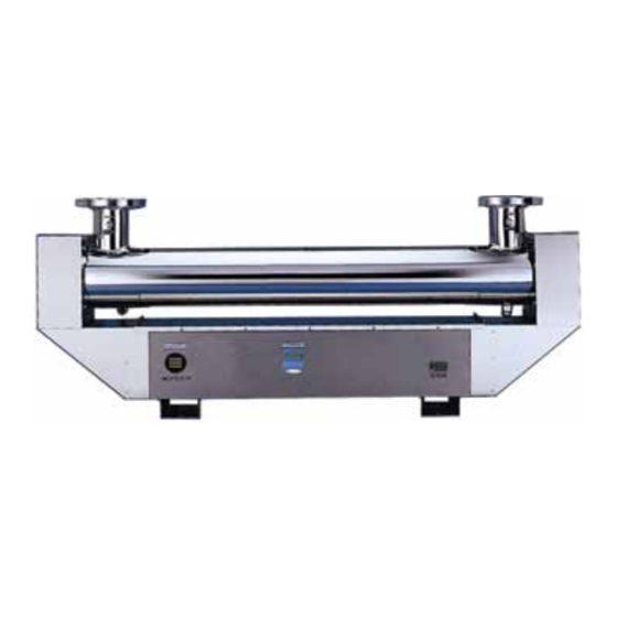
DESCRIPTION THE CSL SERIES The CSL Series has been designed to offer low pressure UV technology over a wide range of application flow rates. The models in this series combine the electrical enclosure and the treatment chamber in one integral unit. The CSL series is the appropriate choice for many treatment applications, offering a more compact footprint and easy installation. -
Page 8: Quartz Sleeves & Lamps
DESCRIPTION QUARTZ SLEEVES & LAMPS STANDARD CONTROL PANEL The quartz sleeves and lamps fit inside the UV chamber. The The control panel contains the ballast(s) and controller for the lamp sockets connect to the lamps, creating a water resistant unit. Different electrical configurations are available. The UV seal and a vibration proof grip. -
Page 9: Installation
INSTALLATION C. The power requirements for each unit depends on INSTALLATION GUIDELINES the number and type of lamps used in the treatment The following are the guidelines and procedures for installing chamber. the CSL Series. D. The units incoming power (120VAC or 240VAC) location requires a single phase, grounded neutral source. - Page 10 INSTALLATION B. Verify the location is free from vibration, which could be caused by proximity to heavy equipment and the erratic or improper pumps. Excessive vibration will damage internal electrical components and cause premature failure of the UV lamps. C. Install a drain valve and pipe to drain. D.
-
Page 11: Quartz Sleeve Install
INSTALLATION QUARTZ SLEEVE INSTALLATION The quartz sleeves designed for this series is open on both ends, N. Retest until a leak-free installation is verified. for USD/CSL style, on one end. The following are the guidelines O. You are now ready to install the lamps. and procedure for quartz sleeve installation. - Page 12 This document is not to be copied, electronically stored or reproduced without written permission from Aquafine Corporation.
-
Page 13: Lamp Install
INSTALLATION DE UV LAMP INSTALLATION The following procedures are for units manufactured with Double- ended lamp design prior to 1999. Once it has been verified that there are no leaks in the system, the unit is ready for UV lamp installation. Remove all power to the UV unit. -
Page 14: Se Lamp Install
SE UV LAMP INSTALLATION SE UV LAMP INSTALLATION The following procedures are for units manufactured with Single-ended (SE) lamp design. Once it has been verified that there are no leaks in the system, the unit is ready for UV lamp installation. -
Page 15: Ht Lamp Install
INSTALLATION HT LAMP INSTALLATION firm connection of all lamps and lamp sockets. The following procedures are for units High Temperature (HT) units. Since it has been verified that there are no leaks in the Secure the PVC alignment plate into postion with the lock system, the unit is ready for UV lamp installation. - Page 16 This document is not to be copied, electronically stored or reproduced without written permission from Aquafine Corporation.
-
Page 17: Operation
OPERATION OPERATIONAL GUIDELINES owering Prior to turning on the UV unit, the following must be verified: Release the pressure in the UV treatment chamber before attempting to remove the protective covers A. The UV chamber should be filled with water. The flow and sealing items. - Page 18 This document is not to be copied, electronically stored or reproduced without written permission from Aquafine Corporation.
-
Page 19: Analog Controller
ANALOG CONTROLLER ANALOG The S-254 is a discrete photo-optical sensing probe placed in the treatment chamber, which monitors the relative change in The following is a description of the LAMP STATUS DISPLAY lamp output through the fluid. Initially, when the UV system featured on your system. -
Page 20: 4-20Ma
ANALOG CONTROLLER Verify the quartz sleeves are clean. If the Gradually start at the normal flow rate. fouling of the quartz sleeve is the cause of the alarm activation, the quartz must be cleaned Bring the unit up to normal operating pressure and at the same time, the UV sensor probe and temperature. -
Page 21: Uv & Temperature Monitoring System
UV & TEMP MONIT. SYSTEM OPERATION UV & TEMPERATURE MONITORING SYSTEM Alarm Display Screen The first line of the alarm display indicates the relative UV There will be an BEEP sound as the unit is initialized. The intensity alarm set point. The second line indicates temperature Monitoring station is a combination UV and temperature alarm set point. -
Page 22: Setting Parameters
UV & TEMP MONIT. SYSTEM OPERATION menu indicating “UV DISPLAY” The UV intensity alarm set point (“UV ALARM”) Use the UP/DOWN arrows to scroll to “RETURN” A. ON (set point) – To enable UV alarm – “ENTER” (DEFAULT) B. EDIT – Select UV alarm set point The display should be at the main operating screen 20-90% indicating UV intensity and temperature... -
Page 23: Setting Temp. Units (°F Or °C)
UV & TEMP MONIT. SYSTEM OPERATION Then again scroll to “RETURN” – “ENTER” The main menu will indicate “UV LEVEL”, the sub menu will display an actual UV intensity value The display should be at the main operating screen – “ENTER” indicating UV intensity and temperature The “MAIN MENU”... - Page 24 This document is not to be copied, electronically stored or reproduced without written permission from Aquafine Corporation.
-
Page 25: Maintenance
MAINTENANCE RECOMMENDED MAINTENANCE • Water quality (tap water, DI water, pH level, chemical content, solids, etc.) GUIDELINES The following provides users of Aquafine UV treatment equipment • Entering water temperature with recommendations and procedures that will maximize the • Flow rate (high, low or constant) efficiency, consistency, reliability and longevity of the equipment. -
Page 26: Safety Requirements
MAINTENANCE SAFETY REQUIREMENTS cleaning tHe unit The following safety requirements are mandatory. Failure to Depending on the environment of the installation, clean carefully follow them can cause injury to the operator and the exterior surfaces of the UV treatment chamber, and damage to the UV unit. -
Page 27: Cleaning The Quartz Sleeves
MAINTENANCE inSpection for leakS cleaning tHe quartz SleeVeS To ensure there are no leaks, a visual inspection of the treatment Visually inspect the quartz sleeve thirty days after use to see chamber should be made. The source of any leaking should be if any debris or film has settled on the outside. -
Page 28: Inspection For Lamp Operation
MAINTENANCE • Replace O-ring and then reassemble all components lamp Socket inSpection in reverse order. When replacing lamps, inspect the lamp socket contacts and related hardware. They should be inspected for corrosion of the metal contact, deterioration of the metal or burning. Be sure all power to the equipment is disconnected. - Page 29 MAINTENANCE Isolate the old ballast from the rest of the system by Remove the lamps socket(s) from the faulty UV lamp disconnecting the ballast connector. base. Remove and discard the old or defective ballast. Use a voltmeter and set an operating range at >700VAC.
- Page 30 MAINTENANCE meaSuring performance Every UV unit should be tested periodically to verify actual efficiency. Regardless of the intended application or any optional equipment that may have been provided with the unit, the most accurate and dependable procedure is to conduct post-UV sample analysis in accordance with standard testing methods.
-
Page 31: Troubleshooting
ANALOG TROUBLESHOOTING SYSTEM NOT OPERATING SYMPTOM PROBABLE CAUSE REMEDY T-120 Temperature Controller If T-120 Option: If the unit is equipped with a System not operating. T-120, the unit will automatically shut OFF when the temperature exceeds 120°F. When the water temperature cools down to below less than 100°F, the unit will turn back ON. -
Page 32: Analog
TROUBLESHOOTING ANALOG LEAKING SYMPTOM PROBABLE CAUSE REMEDY Compression nut Inspect the compression nut and O-ring to insure Leaking that they are installed properly. Over pressure limit System pressure greater than the design pressure will cause the sealing material to fail. Gasket failure The gasket and O-rings should be inspected for deterioration. - Page 33 ANALOG TROUBLESHOOTING LAMP FAILURE SYMPTOM PROBABLE CAUSE REMEDY Ballast power The ballast controls the current to the lamps. The Premature lamp failure lamps current should be measured to determine if within specification. Magnetic ballast should produce 0.425A Electronic ballast should produce 0.35A HE ballast should produce 0.8A Lamp cycling Systems in which the UV is turned ON and OFF...
- Page 34 TROUBLESHOOTING ANALOG LAMP SOCKET BURNING SYMPTOM PROBABLE CAUSE REMEDY Lamp Socket A defective lamp socket can cause a lamp socket Lamp socket burning to fail and burn. Within the lamp socket assembly are metallic receptacles. If the receptacles do not make proper contact with the lamp pins, a high resistance short will occur, eventually resulting in heat build up in the interior of the socket.
- Page 35 ANALOG TROUBLESHOOTING UV SENSOR SYMPTOM PROBABLE CAUSE REMEDY Temperature UV output of the lamps is sensitive to temperature. UV Sensor declining If the UV sensor is set with a water temperature of 70°F and the operational temperature is 50°F, the sensor reading will be less. The sensor should be set to the “normal”...
-
Page 36: Uv & Temperature Monitoring System
TROUBLESHOOTING ANALOG UV & TEMPERATURE MONITORING SYSTEM NOT OPERATING SYMPTOM PROBABLE CAUSE REMEDY Check Power Check the supply voltage to the unit. No Display Voltage Selector Switch The Voltage Selector Switch on the printed on the Printed Circuit Board (PCB) must be selected to the supply voltage. - Page 37 ANALOG TROUBLESHOOTING TESTING THE DETECTOR SYMPTOM PROBABLE CAUSE REMEDY Check the temperature output Measure the voltage between the WHITE wire and Measure with Voltmeter the BROWN wire. The voltage should be between on DC 0-2.5V DC. At 70°F, V=0.7V DC At 80°F, V=0.8V DC At 90°F, V=0.9V DC Check the UV output...
- Page 38 This document is not to be copied, electronically stored or reproduced without written permission from Aquafine Corporation.
- Page 39 UV & TEMP. MONIT. SYSTEM TROUBLESHOOTING RED SCREEN SYMPTOM PROBABLE CAUSE REMEDY Screen is flashing RED Water temperature is above Set Point If the water temperature is above the Set Point, the screen will flash RED. Loose connection on cable A loose or disconnected connection can result in a false reading.
- Page 40 TROUBLESHOOTING UV & TEMP. MONIT. SYSTEM TESTING THE DETECTOR SYMPTOM PROBABLE CAUSE REMEDY Check the temperature output Measure the voltage between the WHITE wire and Measure with Voltmeter the BROWN wire. The voltage should be between on DC 0-2.5V DC. At 70F°, V=0.7V DC At 80F°, V=0.8V DC At 90F°, V=0.9V DC...
-
Page 41: Warranty
WARRANTY NOTE: To register your UV system for warranty, go online to The following installation and operating conditions are considered hazardous and damaging to the equipment,compromising the www.aquafineuv.com ability of the Aquafine unit to perform as intended. REMEMBER, ALWAYS USING GENUINE AQUAFINE PARTS Any of the following conditions will void the equipment KEEPS YOUR WARRANTY, UL, CE &... - Page 42 This document is not to be copied, electronically stored or reproduced without written permission from Aquafine Corporation.
- Page 43 AQUAFINE EQUIPMENT WARRANTY The following terms and conditions will govern the equipment warranty provided by Aquafine Corporation Inc. to the Owner/Operator: Aquafine Corporation (“Aquafine”) warrants to the Owner/Operator noted above (the “Customer”) that if within 12 months from equipment start-up or 18 months from the date of delivery, whichever comes first, equipment manufactured by Aquafine (the “Equipment”) will be free from defects in material and workmanship and will function in accordance with the specifications agreed to by Aquafine for the Equipment.
- Page 44 This document is not to be copied, electronically stored or reproduced without written permission from Aquafine Corporation.
- Page 46 Pure Quality The principles of customer dedication, product quality and reliability are essential in ensuring the purity of water. With innovation and advanced expertise, Aquafine continues to be the world leader in UV water treatment systems for Industrial & Commercial applications. Aquafine is an ISO 9001:2008 certified company.
Need help?
Do you have a question about the Aquafine CSL Series and is the answer not in the manual?
Questions and answers