Table of Contents
Advertisement
Quick Links
PLEASE KEEP FOR PERMANENT REFERENCE
DISINFECTION • TOC REDUCTION • OZONE DESTRUCTION • CHLORINE/CHLORAMINE DESTRUCTION
TrojanUVLogic Series
Installation & Operation Manual
A TROJAN TECHNOLOGIES COMPANY
READ THIS MANUAL
Part Number 127 Rev E
It is imperative that those responsible for the installation
of this equipment, as well as operating personnel, read this
manual and carefully follow all instructions and guidelines.
EQUIPMENT OPERATORS AND INSTALLERS MUST COM-
PLY WITH OPERATIONAL SAFETY REQUIREMENTS.
Advertisement
Chapters
Table of Contents

Related Manuals for Trojan Technologies Aquafine TrojanUVLogic Series


Summary of Contents for Trojan Technologies Aquafine TrojanUVLogic Series
- Page 1 A TROJAN TECHNOLOGIES COMPANY READ THIS MANUAL PLEASE KEEP FOR PERMANENT REFERENCE Part Number 127 Rev E DISINFECTION • TOC REDUCTION • OZONE DESTRUCTION • CHLORINE/CHLORAMINE DESTRUCTION TrojanUVLogic Series Installation & Operation Manual It is imperative that those responsible for the installation of this equipment, as well as operating personnel, read this manual and carefully follow all instructions and guidelines.
- Page 2 Place System Label Here. If no label has been placed here, refer to the label on the UV Equipment for details. For further clarification of label information, please refer to Chapter 2, page23, “System Verification Label Definitions”. Record system set points indicated below: UV Intensity Set Point TM The TrojanUVLogic in this manual may be covered by one or more of the following United States (US) Patents: US 6,342,188 US 6,564,157 US 6,659,431 US 6,635,613 OTHER PATENTS MAY BE PENDING. COPYRIGHT © 2008 by AQUAFINE CORPORATION ALL RIGHTS RESERVED TM TrojanUVLogic Revision: E Last Update: 07AU21 ...
-
Page 3: Table Of Contents
Volume Table of Contents PREFACE GENERAL INFORMATION ........................III IMPORTANT CONTACTS........................IV WARNINGS AND PRECAUTIONS ......................V GENERAL LOCKOUT PROCEDURES ....................XI Lockout and Tag Procedure....................... xi LIST OF ACRONYMS/GLOSSARY ...................... XII TROJANUVLOGIC MAINTENANCE REQUIREMENTS ..............XIII Maintenance Schedule ........................xiv Maintenance Checklist........................ - Page 4 Volume Table of Contents Main Menu Screen........................7-18 Active Alarms Screen........................7-18 Alarms List Screen Series......................7-18 Alarm History Screen ........................7-18 Alarm History Details Screen ......................7-18 Digital Input-Output Screen Series ....................7-19 Operator Access Level Screens ........................7-19 Technician Level Access Screens ......................7-19 Analog Input-Output Screen Series ....................
- Page 5 Volume Table of Contents UV Sensor................................7-3 External Interfaces ............................7-3 SCADA Communication (Optional).......................7-3 Alarms .................................7-3 Auto Home Position Reset (if Wiper is provided)..................7-4 Reactor Proximity Switch Input (Rev Counter)...................7-4 Alarm Output Relays ............................7-4 7.2 CONTROL PANEL (CP) HARDWARE ...................7-5 Description ............................7-5 Specifications ..............................7-5 Maintenance...............................7-6 Power Pack.............................
- Page 6 Volume Table of Contents 5 MECHANICAL WIPING SYSTEM (OPTIONAL) 5.1 INTRODUCTION ..........................5-1 Description ............................5-1 5.2 MANUAL MECHANICAL WIPING SYSTEM (MMWS) (OPTIONAL) ..........5-1 Description ............................5-1 Maintenance ........................... 5-1 Manual Wiper Assembly Removal ........................5-1 Push Retainer Replacement..........................5-2 Sleeve Wiper Replacement (MMWS).......................5-3 5.3 AUTOMATIC MECHANICAL WIPING SYSTEM (AMWS) (OPTIONAL) ........5-5 Description ............................
- Page 7 Volume Table of Contents Control System Overview ....................... 2-3 2.3 SYSTEM VERIFICATION LABEL DEFINITIONS ................2-4 3 START UP AND SHUT DOWN PROCEDURES 3.1 START UP UV SYSTEM .........................3-1 3.2 SHUT DOWN UV SYSTEM ......................3-1 4 UV REACTOR (UVR) 4.1 INTRODUCTION ..........................4-1 Description ............................
- Page 8 Volume Table of Contents 9.4 AUTOMATIC MECHANICAL WIPING SYSTEM (AMWS) INSTALLATION ........9-4 9.5 SYSTEM START-UP ........................9-4 Appendices....................APPENDIX A ........................WARRANTY ........................Certificate of Equipment Warranty APPENDIX B .....................REPLACEMENT PARTS LIST APPENDIX C..........................LAYOUT DRAWINGS ........LG0001D01 - STD., UVLOGIC SHORT LAMP 40 SERIES (AMWS AND NO WIPING) ........LG0004D01 - STD., UVLOGIC LONG LAMP 50 SERIES (AMWS AND NO WIPING) ............LG0005D01 - STD., UVLOGIC LONG LAMP 30 SERIES (NO WIPING) ..............LG0006D01 - STD., UVLOGIC LONG LAMP 30 SERIES (MMWS)
- Page 9 PREFACE Preface ....................iii GENERAL INFORMATION ..........................III IMPORTANT CONTACTS..........................IV WARNINGS AND PRECAUTIONS........................V GENERAL LOCKOUT PROCEDURES ......................XI Lockout and Tag Procedure...........................xi LIST OF ACRONYMS/GLOSSARY........................XII TM TROJANUVLOGIC MAINTENANCE REQUIREMENTS................XIII Maintenance Schedule ..........................xiv Maintenance Checklist..........................xvi Alarm Log..............................xviii System Operating Parameters........................xix Maintenance Log............................xx Lamp Log Table ............................xxi TM TrojanUVLogic Operations & Maintenance i ...
- Page 10 PREFACE TM TrojanUVLogic Operations & Maintenance ...
-
Page 11: General Information
PREFACE PREFACE WARNING General Information ONTAINS INFORMATION THAT IF Congratulations on your purchase of the , NOT HEEDED MAY RESULT IN TM TrojanUVLogic INJURY TO PERSONNEL OR . EQUIPMENT DAMAGE This Operations and Maintenance (O&M) Manual provides instructions on how to operate the system and carry out routine maintenance. CAUTION The objective of this manual is to provide simple, clear and complete instructions. It is ELLS READERS WHEN CARE IS backed by Aquafine Corporations commitment NEEDED TO PREVENT EQUIPMENT . to offer superior customer support. Every effort DAMAGE has been taken to ensure the accuracy and completeness of information in this manual. Note: ROVIDES COMMENTS WHICH CLARIFY If you do not understand any of the . INFORMATION information or procedure explanations in This section of the O&M Manual contains this manual, call your Aquafine Service Provider for assistance. Important Contacts, Warnings and Precautions, General Lockout Procedures, and a List of Do not undertake operation, repairs or Acronyms and Glossary of Terms. ... -
Page 12: Important Contacts
PREFACE Appendices include a variety of material such as Electrical Drawings, Layout Drawings and the Equipment Warranty. Important Contacts AQUAFINE CORPORATION † Head Office (Canada) Europe 29010 Avenue Paine Aquafine GmbH Valencia, CA 91355 Ramskamp 7785 Toll Free: 18004233015 D25337 Elmshorn (outside CA, within USA & Canada only) Germany Phone: 6612574770 Phone: +49 (4121) 5780613 Fax: 6612572489 Fax: +49 (4121) 5780630 † For projects in Continental Europe Internet: www.aquafineuv.con Local Representative TM TrojanUVLogic Operations & Maintenance iv ... -
Page 13: Warnings And Precautions
PREFACE Warnings and Precautions Please read warnings and precautions before proceeding with operation, maintenance or repair of the equipment. Always follow local safety codes and ensure tools and personal protective equipment are in good condition and properly fitted and tested. WARNING Wear UV Resistant Face Shield! NPROTECTED EXPOSURE TO ULTRAVIOLET LIGHT CAN CAUSE SEVERE BURNS TO THE EYES AND . SKIN ACE SHIELD SHOULD BE WORN AS THE PRIMARY PROTECTION AGAINST SUCH EXPOSURE EVER LOOK DIRECTLY AT THE ENERGIZED AMPS UNLESS YOU ARE WEARING ULTRAVIOLET ) RESISTANT FACE SHIELD OR GLASSES FOR SHORT TERM EXPOSURE Eye Protection Must be Worn! , , S ADDED PROTECTION OR AS A MINIMUM PROTECTION FOR SHORT TERM EXPOSURES TIGHT FITTING GLASSES WITH SIDE SHIELDS PROTECTION WHERE SUCH SHIELDS ARE CONTIGUOUS MUST BE WORN AT ALL TIMES WHEN THERE IS A POTENTIAL EXPOSURE TO LTRAVIOLET LIGHT LASSES . SUCH AS WRAP AROUND STYLE ARE MOST EFFECTIVE Wear Protective Gloves! . ... - Page 14 PREFACE WARNING Electrical Hazard! , LOCK ECAUSE OF THE POTENTIAL HAZARD FROM THIS POWER SOURCE IT IS PRUDENT TO USE OUT TAG , PROCEDURES AND ALL SOURCES OF POWER BEFORE PERFORMING ANY MAINTENANCE CLEANING OR REPAIRS ON ANY PIECE OF EQUIPMENT HE POWER SOURCES MAY INCLUDE ELECTRICAL OR STORED ENERGY EFER TO THE GENERAL LOCK OUT AND TAG PROCEDURES IN . THIS MANUAL Wear Hard Hat! EAR AN APPROVED HARD HAT AND OTHER PERSONAL PROTECTIVE EQUIPMENT THAT IS REQUIRED , ACCORDING TO CONSTRUCTION SITE WASTEWATER OR WATER TREATMENT PLANT SAFETY . REGULATIONS Trip Hazard! . TAY ALERT AND BE AWARE OF POTENTIAL TRIP HAZARDS BEFORE WORKING ON EQUIPMENT Hot Surface! . LLOW ELECTRONIC BALLAST AND AMPS TO COOL BEFORE HANDLING . H . LTRAVIOLET AMPS BECOME HOT DURING OPERATION OT AMPS CAN CAUSE SERIOUS BURNS . ...
- Page 15 PREFACE WARNING | ) UPPLY ) FF UPPLY ! ROTECTIVE ARTH ERMINAL ! INCH AZARD ONSULT YOUR TECHNICAL MANUAL BEFORE SERVICING TM TrojanUVLogic Operations & Maintenance ...
- Page 16 PREFACE CAUTION . E HE AMPS IN THIS SYSTEM EMIT ULTRAVIOLET LIGHT XPOSURE TO ULTRAVIOLET LIGHT CAN CAUSE . N SERIOUS BURNS TO UNPROTECTED EYES AND SKIN EVER VIEW ULTRAVIOLET LIGHT DIRECTLY WITH . A UV . THE NAKED EYE LWAYS USE THE PROPER PROTECTIVE EYEWEAR OR A RATED VIEW PORT . E LWAYS WEAR PROTECTIVE CLOTHING WHEN EXPOSED TO ULTRAVIOLET LIGHT NSURE ALL AMPS UVR . T ARE PROPERLY SECURED WITHIN THE CHAMBER BEFORE TURNING THE SYSTEM ON URN THE . SYSTEM OFF BEFORE SERVICING , O PREVENT ELECTRICAL SHOCK TURN THE SYSTEM OFF BEFORE REMOVING ANY OF THE COVERS ON UVR . THE CHAMBER OR OPENING THE ONTROL ANEL , ...
- Page 17 PREFACE CAUTION . T SSEMBLIES HIS IS TO MAINTAIN FULL WIPING COVERAGE OF THE LEEVES AND PREVENT JAMMING . OF THE IPER SSEMBLY ON THE OUTLET END OF THE CHAMBER , F YOU HEAR OR SUSPECT LEEVE BREAKAGE DO NOT WIPE BY RESETTING THE POWER OU WILL . BREAK MORE LEEVES OR AMPS . NSTALLATION AND MAINTENANCE TO BE PERFORMED BY QUALIFIED PERSONNEL ONLY . HIS SYSTEM IS DESIGNED ONLY FOR INDOOR USE . HIS SYSTEM CAN DISINFECT ONLY WATER . EVER OPERATE THE UNIT WHILE EMPTY OR WITHOUT FLOW FOR AN EXTENDED PERIOD . PERATE THE SYSTEM ONLY IF THE CHAMBER IS COMPLETELY FILLED WITH FLOWING WATER NTERMITTENT OPERATION OF THE SYSTEM REQUIRES THAT A MINIMUM AMOUNT OF WATER FLOWS . THROUGH THE SYSTEM IN ORDER TO COOL THE AMPS AC ONNECT THIS SYSTEM ONLY TO POWER THAT CONFORMS TO THE INFORMATION IN THE RATING . PLATE AS REGARDS VOLTAGE AND VOLTAGE SPECIFICATION , F YOUR SYSTEM RUNS WITH PULSE COMPRESSION A BUFFER TANK OR OTHER REMEDIAL MEASURE ...
- Page 18 PREFACE CAUTION ATTENTION OBSERVE PRECAUTIUONS FOR HANDLING ELECTROSTATIC SENSITIVE DEVICES TM TrojanUVLogic Operations & Maintenance x ...
-
Page 19: General Lockout Procedures
PREFACE 3. Attach your Lock and Safety Tag to the Rotary General Lockout Procedures Disconnect Switch. Include your name, date and time, and the work to be performed on the The following lockout procedure is the minimum tag. requirement. Additional precautions should be 4. Return to the Control Panel (CP) and verify taken depending on sitespecific protocols. correct power source has been locked out. Always check with the plant manager and senior electrician for additional precautions. WARNING WARNING HE EQUIPMENT MAY HAVE UV YE ROTECTION EAR ! E STORED ENERGY NSURE THAT ESISTANT ACE HIELD WHEN ALL PARTS HAVE STOPPED LOOKING AT AMPS OR EACTION MOVING AND ANY STORED . HAMBER CAPACITANCE HAS BEEN . EFFECTIVELY DRAINED WARNING 5. ... -
Page 20: List Of Acronyms/Glossary
PREFACE MAX Maximum List of Acronyms/Glossary MGD Millions of Gallons per Day mg/l – Milligrams per liter This glossary defines a list of acronyms that will MIN – Minimum be found throughout this manual. 2 mJ/cm Millijoules per square centimeter MLD Millions of Liters per Day o C – Degrees Celsius mm Millimeters AC – Alternating Current MMWS Manual Mechanical Wiping System is _L Long Lamp Logic Model an optional component that provides the AMWS Automatic Mechanical Wiping System is operator the ability to wipe the Lamp Sleeves an optional component that provides automated during normal operation. wiping of the Lamp Sleeves during normal MPa Megapascals operation. 2 mW/cm Milliwatts per square centimeter ANSI – American National Standards Institute . N m – Newton meter _S Short Lamp Logic Model nm – Nanometers Bar Barometric Pressure NPT – National Pipe Thread BSP – British Standard Pipe O&M Operations and Maintenance CCB – Communication Control Board OH – HydroxylFree Radicals ... -
Page 21: Trojanuvlogic Tm Maintenance Requirements
PREFACE TM TrojanUVLogic Maintenance Requirements CAUTION HIS SYSTEM USES ULTRAVIOLET LIGHT TO REDUCE THE CONCENTRATION OF PATHOGENS TO A NON INFECTIOUS LEVEL OBSERVANCE OF THE MAINTENANCE INSTRUCTIONS OR THE ALARM MESSAGES WILL DIMINISH THE EFFECTIVENESS OF . R THIS SYSTEM EQUIRED DISINFECTION EFFECTIVENESS IS NO LONGER GUARANTEED AND THAT THE REQUIREMENTS OF THE WATER SUPPLY REGULATIONS . A . ARE NO LONGER BEING MET HEALTH RISK EXISTS Periodic inspection and service can extend service life, especially under extreme operating conditions such as batch production scenarios where the internal temperature of the UVR may vary greatly. In such applications, it is recommended that an internal inspection be completed periodically. Routine maintenance typically consists of partial disassembly, cleaning and visual evaluation of system components. Maintenance Requirements must be completed in order to adhere to warranty requirements. Along with the Maintenance Schedule, there are two Maintenance checklists (simply put in the date, and initial the task completed). These tables must be kept up to date at all times to avoid breach of contract which could void the warranty. Four other forms that are provided to make troubleshooting easier are as follows: 1. Alarm Log should be filled out at all times to aid in troubleshooting. 2. System Operating Parameters should be filled out daily for the purpose of viewing trends, if a problem arises. 3. Maintenance Log – This information needs to be filled out to know what was replaced, when and why, again primarily for the purpose of troubleshooting. 4. ... -
Page 22: Maintenance Schedule
PREFACE Maintenance Schedule Refer to applicable sections of the O&M for specific instructions on how to access components and complete the following checks. Daily: Check Current Alarm History on CP operator interface Check Current Alarms, Alarm q Status and Alarm History screens for any new faults. (5 min) Complete System Operating Parameters Checklist. q Check for leaks. q Monthly: * Monthly procedures may be required more frequently if either a low dose alarm occurs or if the UVR has been turned off for a long period of time. If Enclosure is Type 3R or made of 304 SST, check CP Fan Filters for buildup. Replace q if necessary. Ensure all of the Sleeve Nuts are tight. q Remove end cap. Initiate a wipe sequence. Observe the Motor action and wipe q sequence, listening for unusual noises or vibration which could indicate Wiper fatigue. Ensure UV Lamps power is OFF before initiating this procedure. Keep hands away from Gear Motor while operating. (10 minute task). If a Wiping System is not provided, check the Quartz Sleeves for fouling. Remove a q representative sample of Quartz Sleeves. If external fouling present, remove and clean all Quartz Sleeves. If internal fouling is present replace the Sleeve. (10 minute task per Sleeve with UVR drained). Check UV Sensor Window for fouling. If external fouling present, remove and clean the q UV Sensor Window. If internal fouling is present replace the UV Sensor. (5 minute task with UVR drained). Note: Cleaning frequencies are recommendations and should be used as a guideline. q Individual systems may vary depending on effluent quality, algae buildup, etc. 1 year: ... - Page 23 PREFACE Inspect the Roller Bearing. (5 min. task per component after accessed). q Check Elastomer Compression Spring. (5 min. task per component after accessed). q Check Limit Switch Rod Seals. (5 min. task per component after accessed). q Check Busing Housing ORing for leakage. (5 min. task per component after accessed). q 9000 Runtime Hours: Replace all Lamps. (10 min task per Lamp once accessed). q TM TrojanUVLogic Operations & Maintenance xv ...
-
Page 24: Maintenance Checklist
PREFACE Maintenance Checklist M = Monthly Y = Yearly Manually hand M clean Sleeves Manually hand M clean UV Sensor Check for UV Y Decay of Sleeve Seal ORings Check for UV Y Decay of Sleeve Support Washer Check for UV Y Decay of Sleeve Bushing Check for UV Y Decay of Wear Pads Inspect Lamp Y Socket Check UVR Y Chamber for heavy build up of settled solids Check Sleeve Y Wiper Check Rod Seal Y for leakage at Drive Screw ... - Page 25 PREFACE M = Monthly Y = Yearly Manually hand M clean Sleeves Manually hand M clean UV Sensor Check for UV Y Decay of Sleeve Seal ORings Check for UV Y Decay of Sleeve Support Washer Check for UV Y Decay of Sleeve Bushing Check for UV Y Decay of Wear Pads Inspect Lamp Y Socket Check UVR Y Chamber for heavy build up of settled solids Check Sleeve Y Wiper Check Rod Seal Y for leakage at Drive Screw Check Stop Plate ...
-
Page 26: Alarm Log
PREFACE Alarm Log (Record All Alarms in this table) ALARM DATE TIME ALARM DESCRIPTION RESOLVED (Y/N) TM TrojanUVLogic Operations & Maintenance xviii ... -
Page 27: System Operating Parameters
PREFACE System Operating Parameters Date Time Flow UV UV UV UV UVR 1 UVR 2 UVR 3 UVR 4 (Units Intensity Intensity Intensity Intensity Power Power Power Power _____) UVR 1 UVR 2 UVR 3 UVR 4 (%) (%) (%) (%) Monday Tuesday Wednesday Thursday Friday Saturday Sunday System Lamp Lamp ... -
Page 28: Maintenance Log
PREFACE Maintenance Log (Use of this form to record all Maintenance) DATE TIME DETAILS PARTS OPERATOR USED/ORDERED INITIALS TM TrojanUVLogic Operations & Maintenance xx ... -
Page 29: Lamp Log Table
PREFACE P Lamp Log Table Project Name: ________________________ Date: ____________________ Completed By: _________________________ Company Name Reactor Lamp Lamp Hours Date Installed Date Changed This form must be completed and submitted to Aquafine Corporation with all requests for warranty replacements for Lamps. Individual Lamp premature failure information should also be transferred to the outside of the Lamp packaging for the returned Lamps. For Aquafine Use: MTR Initials: Date Received: Date Completed: Ref: Sales Order # RA (Y/N) & #: TM TrojanUVLogic Operations & Maintenance xxi ... - Page 30 TROJANUVLogic...
-
Page 31: Introduction To Uv Theory
Introduction to UV Theory Chapter 1 INTRODUCTION TO UV THEORY Trojan ogic Operations & Maintenance... - Page 32 Introduction to UV Theory Trojan ogic Operations & Maintenance 1-ii...
- Page 33 Introduction to UV Theory 1 Introduction To UV Theory ..............1-1 1.1 OVERVIEW OF TROJANUVLOGIC ......................1-1 1.2 WHAT IS ULTRAVIOLET LIGHT? ........................1-1 1.3 DISINFECTION VS. STERILIZATION ......................1-2 1.4 APPLICATIONS OF UV LIGHT ........................1-2 1.5 FACTORS AFFECTING UV DISINFECTION ....................1-2 UV Transmittance:............................
- Page 34 Introduction to UV Theory Trojan ogic Operations & Maintenance 1-iv...
-
Page 35: Overview Of Trojanuvlogic
Introduction to UV Theory 1 INTRODUCTION TO UV THEORY 1.2 What Is Ultraviolet Light? UV light is defined as electromagnetic radiation having a wavelength less than that of visible 1.1 Overview of TrojanUVLogic light (400 Nm) and greater than that of X-Rays The TrojanUVLogic uses ultraviolet light to (100 Nm). -
Page 36: Disinfection Vs. Sterilization
Introduction to UV Theory 1.3 Disinfection vs. Sterilization Chlorine/Chloramines Destruction: UV can replace sodium meta-bisulfite and carbon Sterilization implies the total elimination of technologies to remove chlorine/chloramines pathogens or disease carrying microorganisms. from source water used in industrial In contrast, disinfection is a reduction in the applications. -
Page 37: Uv Transmittance
Introduction to UV Theory Factors Affecting Performance DOSE = INTENSITY(mW/cm RETENTION TIME(sec) Water Quality Flow Rate • UV Transmittance • Suspended Solids • Level of Dissolved Organics • Total Hardness Lamp Condition • Sleeve Cleanliness • Aging Treatment Process UV Transmittance Suspended Solids: UV Transmittance is defined as the percentage Suspended Solids consist of any filterable... -
Page 38: Sleeve Cleanliness
Introduction to UV Theory stream may contribute to coating of the quartz sleeve. Sleeve Cleanliness: To ensure maximum performance from the unit, it is essential that the Quartz Sleeves be kept clean. If a coating is allowed to build up on the sleeves, the amount of the UV light transmitted to the water will be reduced. - Page 39 System Overview Chapter 2 SYSTEM OVERVIEW Trojan ogic Operations & Maintenance...
- Page 40 System Overview Trojan ogic Operations & Maintenance 2-ii...
- Page 41 System Overview System Overview ................2-1 2.1 SYSTEM COMPONENTS ......................2-1 UV Reactor (UVR)............................2-1 Control Panel (CP) ............................2-1 UV Sensor ................................ 2-2 Wiping Systems ............................... 2-2 Automatic Mechanical Wiping System (AMWS)..................2-2 Manual Mechanical Wiping System (MMWS) ................... 2-3 Power Pack..............................
- Page 42 System Overview Trojan ogic Operations & Maintenance 2-iv...
-
Page 43: System Overview
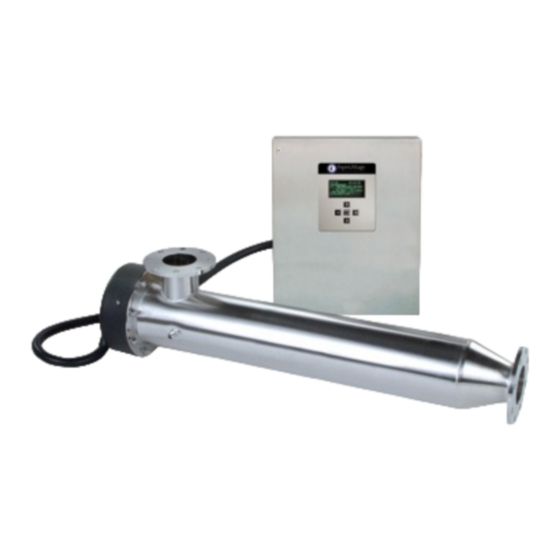
System Overview Stop Plate Reactor Wiper Chamber Assembly 2 SYSTEM OVERVIEW Outlet Flange 2.1 System Components The TrojanUVLogic is made up of several End Cap Inlet Flange components: • UV Reactor (UVR), • Control Panel (CP), • 2” Sanitary UV Sensor Ferrule •... -
Page 44: Uv Sensor
System Overview The Operator Interface to the UV system is Wiping Systems located on the door of the CP Enclosure. The Operator Interface displays system status and (Optional on most models) operational information. Automatic Mechanical Wiping System (AMWS) The AMWS uses food grade rubber wipers UV Sensor contained within a Split Ring Wiper Housing, mounted on a stainless steel Plate, placed... -
Page 45: Manual Mechanical Wiping System (Mmws)
System Overview Manual Mechanical Wiping System (MMWS) Power Pack The MMWS uses food grade rubber wipers The Power Pack will provide step-up or step- contained within a Split Ring Wiper Housing, down power. Any plant power can be converted mounted on a stainless steel plate, placed to the 240VAC split phase power required by the around each of the Quartz Sleeves. -
Page 46: System Verification Label Definitions
System Overview 2.3 System Verification Label Definitions Below are the list of the potential options indicated on the Label and a brief description (Reference Your System Sticker located on your equipment and at the front of this manual to determine your system Specifications) ANSI = American Manual = Manual National Standards Institute (ANSI... - Page 47 System Overview SST = Stainless Steel Required = Provided (Optional when Customer Enclosure Rating: requested – Customer must supply No = No Enclosure power from device.). Provided Not Required = Not Provided (standard). 3R = Type 3R Mounting Brackets: 12 = Type 12 Fixed = Welded Brackets Operating Voltage: Adjustable = Adjustable...
- Page 48 TROJANUVLogic...
- Page 49 Start Up/Shut Down Procedures Chapter 3 START UP AND SHUT DOWN PROCEDURES TrojanUVLogic Operations & Maintenance...
- Page 50 Start Up/Shut Down Procedures TrojanUVLogic Operations & Maintenance 3-ii...
- Page 51 Start Up/Shut Down Procedures 3 Start Up and Shut Down Procedures ..........3-1 3.1 START UP UV SYSTEM..........................3-1 3.2 SHUT DOWN UV SYSTEM..........................3-1 TrojanUVLogic Operations & Maintenance 3-iii...
- Page 52 Start Up/Shut Down Procedures TrojanUVLogic Operations & Maintenance 3-iv...
- Page 53 Start Up/Shut Down Procedures any false alarms from registering while the 3 START UP AND SHUT DOWN system is warming up. PROCEDURES 6. Depending upon the water temperature, the lamps can take a varying amount of time to reach maximum output. 3.1 Start Up UV System 7.
- Page 54 Start Up/Shut Down Procedures WARNING Electrical Hazard! Because of the potential hazard from this power source, it is prudent to use LOCK OUT procedures and TAG all sources of power before performing any maintenance, cleaning or repairs on any piece of equipment. The power sources may include electrical or stored energy.
- Page 55 UV Reactor (UVR) Chapter 4 UV REACTOR (UVR) TrojanUVLogic Operations & Maintenance May 25, 2004...
- Page 56 UV Reactor (UVR) TrojanUVLogic Operations & Maintenance 4-ii May 25, 2004...
- Page 57 UV Reactor (UVR) 4 UV Reactor (UVR) ................4-1 4.1 INTRODUCTION .............................. 4-1 Description ............................... 4-1 Specifications ..............................4-3 Maintenance..............................4-3 4.2 END CAPS ............................... 4-3 Description ............................... 4-3 Specifications ..............................4-3 Maintenance..............................4-3 End Cap Removal & Installation ......................4-3 For Bolt-On Flange Style End Plates (20+cm Diameter Models) ............
- Page 58 UV Reactor (UVR) TrojanUVLogic Operations & Maintenance 4-iv May 25, 2004...
-
Page 59: Uv Reactor (Uvr)
UV Reactor (UVR) drain port fixed to the outer wall. 4 UV REACTOR (UVR) Flow enters parallel to the Lamps and exits through a flange located perpendicular to the UV Lamps. 4.1 Introduction Each UVR is designed for a maximum operating pressure of 150 psi (10 Bar) and has been Description hydrotested to 225 psi (15 Bar) prior to... - Page 60 UV Reactor (UVR) Stop Plate Outlet Flange Chamber Sanitary End Plate Sleeve Support Inlet Flange Washer Stop Plate Sleeve Nut Port Plug (Vent) Sleeve Bushing End Plate Plug UV Lamp Sleeve O-Ring Temperature Sanitary Clamp Switch Clip A high Temperature Switch is mounted Each UVR is provided with a UV Intensity externally on each UVR for safety purposes.
-
Page 61: Specifications
UV Reactor (UVR) Power is provided to each UVR from the Specifications corresponding Control Panel (CP). Each UVR Material: Painted Aluminum or Plastic depending must be wired together with its CP. Please see on model. the section on the CP for more details. Maintenance Specifications CAUTION... -
Page 62: For Sanitary Clamp Style (Up To And Including 20Cm Diameter Chambers)
UV Reactor (UVR) 5. Replace the two Philip screws from the End Specifications Cap. The frequency of Lamp replacement will depend on factors such as: For Sanitary Clamp Style (Up to and including • 20cm diameter chambers) Water Temperature, Max Operating Temperature= 40 C 1. -
Page 63: Maintenance
UV Reactor (UVR) Maintenance Lamp Inspection/Replacement The ultraviolet output of these Lamps decreases WARNING with time. UV Lamps must be replaced every 9000 hours of operation even if Lamp failure has Wear UV Resistant Face CAUTION Shield! Unprotected exposure to The Lamps in this system emit ultraviolet light can cause sever ultraviolet light. - Page 64 UV Reactor (UVR) Alignment Pin Gently pull the Lamp Holders and UV Lamp from the Sleeve Bolt. An internal spring at the far end End Plate of the UV Lamp will push the Lamp out approximately 12 mm (0.5in). Ground Wire SLEEVE LAMP BOLT...
-
Page 65: Elapsed Time Reset
UV Reactor (UVR) 8. Use only quality replacement parts from sliding it down the Lamp, using cotton gloves. If Aquafine Corporation. Use clean gloves there is interference with the UV Sensor gently (cotton) to install the new Lamp. Touching rotate the Lamp until it is situated correctly. the Lamp with bare hands will contaminate 10. -
Page 66: Maintenance
UV Reactor (UVR) 2. Shut the power OFF at the CP. Follow the Lockout and Tag Procedures in the Preface. HOW TO INFO WARNING Electrical Hazard! Maintenance Because of the potential hazard Sleeve Replacement from this power source it is prudent to use LOCK OUT Note: Sleeve replacement can either be... - Page 67 UV Reactor (UVR) 5. Disconnect the Ground Wire and remove the 8. Disconnect Lamps: Follow instructions for Alignment Pin your model. Midflow Models only: End Plate Gently rotate the Lamp Holder a 1/4 turn counter-clockwise and pull the UV Lamp from Ground Wire the Sleeve Bolt.
- Page 68 UV Reactor (UVR) 10. Remove the Sleeve Bolt by hand, turning it 13. Place the Sleeve Support Washer into the in a counter clockwise direction. Sleeve Bolt as shown. Ensure that the Washer seats flat on the recess of the Sleeve Bolt. Use clean gloves (cotton) to remove the Sleeve.
-
Page 69: Sleeve Cleaning
UV Reactor (UVR) Sleeve Cleaning before installation to make sure they are clean and dry. Clean the interior of the Sleeve Cleaning Solutions Sleeves with alcohol if they have been exposed to water or acid solutions. The following cleaning solution is recommended for the removal of scale build-up and coatings 4. - Page 70 UV Reactor (UVR) 1. Turn off the water flow through the UVR 4. Disconnect all UV Sensors from the Conduit Support Bracket. Note: Ensure that the plant has been 5. If there is an End Cap, remove the End Cap from the UVR chamber, as per the End Cap Switched to bypass or plant is shut Removal and Installation instructions earlier...
-
Page 71: Sleeve Bushing Replacement
UV Reactor (UVR) Alignment Pin Sleeve Holder / Wiper Assembly Vent Port Plug Temperature Switch Ground Wire Screw 11. Extract the entire Sleeve Holder / Wiper Assembly from the UVR chamber. Pull the Sleeve Holder / Wiper Assembly in a direction parallel to the UVR chamber to prevent the Quartz Sleeves from striking the sides of the chamber. - Page 72 UV Reactor (UVR) 2. Remove Sleeve Holder Bushings by 4. To remove the Wear Pad turn counter pressing against the small end. clockwise. 3. Insert the replacement Sleeve Holder 5. Insert replacement Wear Pad by turning Bushings from the stamped side of the Stop clockwise slowly until there is full Plate.
-
Page 73: Temperature Switch
UV Reactor (UVR) 4.5 Temperature Switch Description For safety reasons, a Temperature Switch is provided which will trigger a warning alarm and shut the system off if the UVR is running too hot. The High Reactor Temperature alarm is factory pre-set to indicate either Minor or Major alarms for “REACTOR HIGH TEMPERATURE”... - Page 74 UV Reactor (UVR) TrojanUVLogic Operations & Maintenance 4-16 May 25, 2004...
- Page 75 Mechanical Wiping Systems (Optional) Chapter 5 MECHANICAL WIPING SYSTEMS (OPTIONAL) TrojanUVLogic Operations & Maintenance May 25, 2004...
- Page 76 Mechanical Wiping Systems (Optional) TrojanUVLogic Operations & Maintenance 5-ii May 25, 2004...
- Page 77 Mechanical Wiping Systems (Optional) 5 Mechanical Wiping System (Optional)..........5-1 5.1 INTRODUCTION .............................. 5-1 Description ............................... 5-1 5.2 MANUAL MECHANICAL WIPING SYSTEM (MMWS) (OPTIONAL) ............. 5-1 Description ............................... 5-1 Maintenance..............................5-1 Manual Wiper Assembly Removal......................5-1 Push Retainer Replacement........................5-2 Sleeve Wiper Replacement (MMWS)......................
- Page 78 Mechanical Wiping Systems (Optional) TrojanUVLogic Operations & Maintenance 5-iv May 25, 2004...
-
Page 79: Mechanical Wiping System (Optional)
Mechanical Wiping Systems (Optional) The MMWS uses food grade rubber wipers 5 MECHANICAL WIPING SYSTEM mounted into stainless steel collars, placed (OPTIONAL) around each of the Quartz Sleeves. The Wiper Housings for all Sleeves are mounted together onto a common Wiper Assembly. The Wiper 5.1 Introduction Assembly is driven back and forth by hand using an external handle. -
Page 80: Push Retainer Replacement
Mechanical Wiping Systems (Optional) CAUTION 6. Loosen the Strain Relief on the End Cap. (If there is no End Cap, skip the next step). De-Pressurize & Drain the UVR. Pressure must be relieved from 7. Remove the End Cap as per the Follow the the system prior to any End Cap Removal and Installation maintenance, to prevent... -
Page 81: Sleeve Wiper Replacement (Mmws)
Mechanical Wiping Systems (Optional) Sleeve Wiper Replacement (MMWS) 7. Install a new Split Ring Wiper Housing by 1. Complete the Manual Wiper Assembly slowly working it into the hole in the Wiper Removal procedure immediately preceding Plate, as shown below. this step. - Page 82 Mechanical Wiping Systems (Optional) Thrust Stop Washer Plate Wiper Inlet Sanitary Housing Flange End Plate Vent Kit (optional) Wiper Outlet flange Push Retainer Wiper Sleeve Wiper Bushing Vent Plug Ground Plate Screw Rod Seal Lamp Holder Assembly Tie Rod Chamber O-Ring UV Sensor Port Bearing...
-
Page 83: Automatic Mechanical Wiping System (Amws) (Optional)
Mechanical Wiping Systems (Optional) Control Panel (CP). The power requirement given for the CP includes operation of the wiping 5.3 Automatic Mechanical Wiping system. The Wiper Assembly is mounted to the Drive System (AMWS) (Optional) Screw attached to a Carrying Nut that moves the Wiper Assembly along the Drive Screw. - Page 84 Mechanical Wiping Systems (Optional) 5. Remove Jaw Coupling Spider and store it with the Gear Motor Assembly. 3. Unplug the Proximity Sensor cable. 6. When reinstalling the Gear Motor ensure that 4. Remove four 1/4-28 Hex Head Cap Screws all previously mentioned cables are on the Motor Mounting Plate and remove reconnected, but also ensure that the Gear Motor Assembly.
-
Page 85: Stop Plate Bushing Replacement
Mechanical Wiping Systems (Optional) CAUTION Stop Plate Bushing Replacement 1. Remove Gear Motor, following Gear Motor The Sleeves may be left in the Wiper Assembly when the Stop Removal procedure earlier in this chapter. Plate is removed, however, if the 2. -
Page 86: Drive Screw Roller Bearing, O-Ring & Seal Replacement
Mechanical Wiping Systems (Optional) Plate. Drive Screw Roller Bearing, O-ring & Seal 7. Unscrew the Bearing Housing Replacement 8. Slide Drive Screw out through the End Plate. 1. Remove Gear Motor, following Gear Motor Removal procedure earlier in this chapter. 9. -
Page 87: Sleeve Wiper Replacement (Amws)
Mechanical Wiping Systems (Optional) Inlet Flange Wear Pad 12. Install new Roller Bearing by pressing it into Bearing Housing. Push all the way into Housing. 13. Install new Bearing Retaining Ring. Ensure it is properly seated into its groove. 14. Install new O-Ring into Bearing Housing. Ensure it is properly seated into groove. - Page 88 Mechanical Wiping Systems (Optional) Wiper Seal Wiper Plate 6. Carefully insert new Sleeve Wipers into the Wiper Housing Assembly by squeezing them together and letting them pop into place. Ensure that the Wipers are fully seated and that they can float freely in their respective Housings prior to reinserting the Sleeves.
- Page 89 Mechanical Wiping Systems (Optional) Note: The resting position of the wiper Assembly 8. Reassemble chamber. for the 03_S/_L – 08_S/_L is at the Inlet end. The resting position of the wiper Assembly for the 30_L is at the End Plate end and for DIAGRAM REFERS TO AL the 12_S/_L –...
-
Page 90: Drive Nut Removal / Replacement
Mechanical Wiping Systems (Optional) 8. Slide the Drive Screw out through the End Drive Nut Removal / Replacement Plate. 1. Remove Gear Motor, following Gear Motor 9. Remove the Rod Seal from the Bushing Removal procedure earlier in this chapter. Housing noting its position. - Page 91 Mechanical Wiping Systems (Optional) 16. Rotate the Drive Screw until its end is clear of Step 36, since 12_S ‘s only have one Wiper the Wiper Assembly. Plate Assembly. 17. Remove the Jam Nut (s) and Screw Lock 22. Continue to rotate the Drive Screw until it has Washer.
- Page 92 Mechanical Wiping Systems (Optional) 27. Turn one of the Drive Nuts though its Wiper 33. While holding the Drive Nut in position tighten Plate and tighten the Jam Nut onto it. the Jam Nut against the Wiper Plate. 28. Slide the Lock Washer over the Drive Nut 34.
- Page 93 Mechanical Wiping Systems (Optional) Automatic Mechanical Wiping System 03_S/_L – 08_S/_L Models (Venting Shown) 12_S Model design is similar to this diagram Retaining except that the end plate is an ANSI/DIN flange Wiper instead of a sanitary flange. Assembly Sleeve Wiper Stop Plate Assembly Air Vent...
- Page 94 Mechanical Wiping Systems (Optional) TrojanUVLogic Operations & Maintenance May 25, 2004 5-16...
- Page 95 UV Sensor Chapter 6 UV Sensor TrojanUVLogic Operations & Maintenance May 25, 2004...
- Page 96 UV Sensor TrojanUVLogic Operations & Maintenance 6-ii May 25, 2004...
- Page 97 UV Sensor 6 UV Sensor ................... 6-1 6.1 INTRODUCTION .............................. 6-1 Description ............................... 6-1 Specifications ..............................6-1 Maintenance..............................6-1 UV Sensor Removal and Cleaning......................6-1 UV Sensor Replacement ......................... 6-2 TrojanUVLogic Operations & Maintenance 6-iii May 25, 2004...
- Page 98 UV Sensor TrojanUVLogic Operations & Maintenance 6-iv May 25, 2004...
- Page 99 UV Sensor Maintenance 6 UV SENSOR UV Sensor Removal and Cleaning 1. Turn off the water flow through the UVR 6.1 Introduction chamber. Isolate the UVR. Note: Description Ensure that the plant has been The TrojanUVLogic system is provided with a switched to bypass or plant is shut UV Sensor for intensity measurement.
- Page 100 UV Sensor CAUTION De-Pressurize & Drain the UVR. Pressure must be relieved from the system prior to any maintenance, to prevent damage to the equipment or personal injury. 4. Remove the Nut by turning it counter- clockwise. 5. Gently remove the UV Sensor from the UV Sensor port.
- Page 101 Control Panel (CP) Chapter 7 CONTROL PANEL (CP) TrojanUVLogic Operations & Maintenance 2006-01-19...
- Page 102 Control Panel (CP) TrojanUVLogic Operations & Maintenance 2006-01-19 7-ii...
- Page 103 Control Panel (CP) 7 Control Panel (CP) ................7-1 7.1 OPERATIONAL DETAILS ..........................7-1 Controls Philosophy ............................7-1 Control System Overview ........................7-1 UV Reactor Control ..........................7-1 Normal Operation Start-up ........................7-1 Normal Operation ............................ 7-1 Shutdown ..............................7-2 Lamp Control and Monitoring ........................
- Page 104 Control Panel (CP) Operator Interface ............................7-15 Operation..............................7-15 Specifications ............................7-15 Maintenance ............................7-16 7.3 CONTROL PANEL (CP) SOFTWARE......................7-16 Boot Menu Screen ............................7-16 Main Display Screen ............................7-16 UV Sensor ..............................7-16 Reactor Temp Option:............................ 7-17 Main Menu Screen ............................7-18 Active Alarms Screen.............................
-
Page 105: Control Panel (Cp)
Control Panel (CP) When power is restored after an electrical 7 CONTROL PANEL (CP) service interruption, any UVR required for operation will immediately go into a Warm-up mode (refer to the Normal Operation Start-up 7.1 Operational Details heading) before the UV System returns to the previous operational mode. -
Page 106: Shutdown
Control Panel (CP) mode Alarm suspension) + (the adjustable 10 to sequence may be initiated automatically as 999 second Alarm Delay) = minimum 28 or scheduled by the CCB CP controller. maximum 1017 seconds before alarms can be In Automatic mode, the interval between activated after start-up. -
Page 107: Uv Sensor
Control Panel (CP) Position. After a 3 second delay, the CP SCADA Communication (Optional) initiates an extend sequence for 5 revolutions, The Modbus RS485 communication protocol is placing the Wiper in the reset “Park” Position. an optional feature that enables the Control Panel to communicate with and be controlled by If the power to the system becomes the Plant PLC by remote means. -
Page 108: Reactor Proximity Switch Input (Rev Counter)
Control Panel (CP) pauses and travels back to the Park position to alarm, the power will be lost, and the closed wait for the signal to cycle. Whenever the contact will return to its normally open state, Wiper is in operation the controller will change which indicates an alarm. -
Page 109: Control Panel (Cp) Hardware
Control Panel (CP) The CP is a metal enclosure that houses the 7.2 Control Panel (CP) Hardware control electronics and power supplies. The CP may be fan cooled depending on Model requirements and is suitable for indoor Control Panel (CP) Enclosure installation. -
Page 110: Maintenance
Control Panel (CP) Maintenance down power. When incoming supply voltage is not the standard 208 through 240 VAC, a Similar to steel products exposed to the outdoor Power Pack will be required. The Power Pack is environment, the exterior of an enclosure essentially an independent transformer that is installed indoors needs to be washed monthly housed in its own Type 3R enclosure. -
Page 111: Maintenance
Control Panel (CP) Ballast Power Mounting Screw (Typ of 2) Lamp/Ballas t Status Ballast to Lamp Power Ballast for AS and AL Models Ballast for AM Models WARNING 2. Disconnect the Power Cable to the Ballast, as shown below. URFACE 3. -
Page 112: As & Al Model -Ballast Removal & Replacement
Control Panel (CP) AS & AL Model –Ballast Removal & Replacement 1. Disconnect all power to the CP and follow Lockout and Tag procedures which are found in the Preface. WARNING 5. Remove the 2 hex Mounting Screws on either side of the Ballast and lift it out. Electrical Hazard! Because of the potential hazard from this power... - Page 113 Control Panel (CP) 8. Place the new Ballast onto the Back Plate and align onto the Mounting Screw holes. Fasten the Ballast into place. 9. Reinstall the Connectors that provide power to the Lamps on the new Board. 10. Reconnect the Lamp/Ballast status Communication Cable to the correct locations as shown on previous page.
-
Page 114: System Controller - The Control Board
Control Panel (CP) The Board is configured by a user-friendly Operator Interface Menu System and Keypad. System Controller – The Control Board The Board allows the Operator to recall its original factory settings. If for some reason Description someone accidentally changes parameters and is uncertain what they have done, these factory The heart of the control system is a settings are stored right on the Board, and can... -
Page 115: Board Diagram
Control Panel (CP) Note: The terminations required by the contractor include: The Main Power to the Disconnect Switch as shown in the Previous figure. The Alarm terminations Optional Digital Inputs if applicable. (Remote ON/OFF). Board Diagram See the following page. TrojanUVLogic Operations &... - Page 116 Control Panel (CP) CONTROLLER BOARD Lamp Status Connectors SCADA Comm. (Midflow Models RS232 Module Future Only) Temperature Connection Location Switch Ballast Communication Wiper Home Connectors Limit Switch (Short Lamp &Long Lamp Models only) Wiper Proximity Sensor Fan Status Connector 24VDC Analog inputs Processor Chip (Typ.of 5)
-
Page 117: Rs232 Com Port
Control Panel (CP) Display Screen RS232 Com Port The RS232 communications port can accommodate a laptop connection. Ballast Communication Ports The Ballast Communication Ports are used for Keypad Lamp and Ballast Status information, to Connect determine Runtime and Alarm Faults. These 10 Pin ports connect directly by a ribbon cable to the Com Ports on the Ballasts. -
Page 118: Digital Output Relays (If Wiper Is Provided)
Control Panel (CP) 3. Reactor High Temperature (Critical) power. When the condition has ended, this response will de-energize, and the required 4. System On system power level will return. Since the Long 5. Spare (blank) Lamp Models are the only models that have variable power, this option is only available on 6. -
Page 119: Operator Interface
Control Panel (CP) frequency can be adjusted to suit varying site Operator Interface conditions. The Operator Interface is a Florescent Display The buttons at the bottom of the following that is programmed with custom screens. The screens take the Operator to the respective Operator may navigate though the different screens: screens using the 5-button Keypad, as shown... -
Page 120: Maintenance
Control Panel (CP) Models only. The mode will be displayed as either Local or Maintenance Remote. There is no %Power display for Midflow or Short 7.3 Control Panel (CP) Software Lamp models. Local: Control override by Operator at Boot Menu Screen the CP. -
Page 121: Reactor Temp Option
Control Panel (CP) Reactor Temp Option (4 – 20 Analog Required): This screen will only appear if the Reactor Temperature options are configured. This screen provides an overview of the following: Reactor Temp.: Displays the current reactor temperature. Bar Graph: The bar graph depicts live readings. -
Page 122: Main Menu Screen
Control Panel (CP) Main Menu Screen Alarm History Screen The Alarm History Screen can be accessed To enter the Main Menu the Operator must from the Active Alarm Screen by pressing the Press the Enter or Menu button, located in the HIST button. -
Page 123: Digital Input-Output Screen Series
Control Panel (CP) Technician Level Access Screens Digital Input-Output Screen Series To access these screens you must have These screens are accessible through the Main entered the Technician’s Password. Then, from Menu by selecting the Digital Input-Output each of the previous Digital Input/Output Screens. -
Page 124: Analog Input-Output Screen Series
Control Panel (CP) Analog Input-Output Screen Series Technician Level Access Screens Note: Digital input 1 and 2 are optional and will only appear is you have opted to have each or both of these inputs configured with your UV system. These screens can be accessed through the Main Menu by selecting the Analog Input- Output Screens. -
Page 125: System Settings Screens
Control Panel (CP) • the board. Once the corresponding item is SCADAR (SCADA Remote) - displayed, arrow up or down to another line. control by an external device Continue till all lines are configured as required. through SCADA Move the cursor to Save and the press enter communications to accept and keep all changes. -
Page 126: Technician Level Access Screens
Control Panel (CP) Dose Units: The operator can select either mJ/cm2 or J/m2 units to view UV Dose. Note: During startup, the UV Sensor Alarm Delay + an 18 second alarm suspension will occur before an alarm appears. Refer to the Normal Operation heading in this chapter for This screen allows the Operator to adjust the more details. - Page 127 Control Panel (CP) This screen allows the Technician to change This screen allows the Technician to adjust the the following variables: following: Reset Lamp Hours: This field allows the Set Clock: This field allows the Technician to Technician to reset the Lamp adjust the system Time.
-
Page 128: Trend Screens
Control Panel (CP) Trend Screens The Wiper screen provides the Operator with the following information: • Next Wipe In – Displays the time remaining until the next wipe cycle is to occur, indicated in hours. • Wiper Cycle – Indicates how often the Wiper will cycle. -
Page 129: Wiper Sequence Timer (Amws) (For Systems With A Wiper)
Control Panel (CP) The screen also graphically displays the UVR Analog Menu Screen wiping as it is in progress. To access this screen, select Analog Menu Wiper Sequence Timer (AMWS) (For systems with a Wiper) The system is delivered from the factory with a frequency setting of one wiping cycle occurring every 8 hour period. -
Page 130: Login Screen
Control Panel (CP) Login Screen Reactor Hi Temp (Reactor High Temperature) Note: The Login screen will automatically log the user out after 10 minutes. Configure Screen (Optional) If a password has not been entered, the system This screen allows the Operator to adjust the will automatically allow Operator level access following: only. - Page 131 Control Panel (CP) TrojanUVLogic Operations & Maintenance 7-27 2006-1-19...
-
Page 132: System Status Alarm List
Control Panel (CP) 7.4 System Status Alarm List CAUTION This system uses ultraviolet light to reduce the concentration of pathogens to a non-infectious level. Non-observance of the maintenance instructions or the alarm messages will diminish the effectiveness of this system. Required disinfection effectiveness is no longer guaranteed and the requirements of the water supply regulations are no longer being met. -
Page 133: Major Alarms
Control Panel (CP) Major Alarms On a Major alarm immediate action is required by the Operator to ensure that disinfection is not compromised. Alarm relays will be deactivated. Alarm Description Low UV Intensity 1 When the UV Intensity has dropped below the factory set point. Major Multiple Lamp Alarms Multiple lamps are not functioning. -
Page 134: Critical Alarms
Control Panel (CP) Critical Alarms On a critical fault the UVR will be placed into Shutdown. On a Critical alarm the system CP will take immediate action to prevent damage to the equipment and immediate action is also required by the Operator and ensures that disinfection is not compromised. -
Page 135: Input And Output Overview
Control Panel (CP) 7.6 Input and Output Overview Item Inputs / Outputs Type Mode Source Standard Inputs and Outputs UV Sensor (1 – 3) Input Analog 4-20mA System I/O Alarms (7) Output Digital Normally Open Customer I/O (NO) Optional Inputs and Outputs Optional Inputs and Outputs cannot typically override standard provided Inputs and Outputs. -
Page 136: Additional Inputs And Outputs
Control Panel (CP) Additional Inputs and Outputs The following are available for custom applications. This list is not intended to cover all options. It is a representative list of options that sites may wish to exercise. Custom applications, like the ones that follow will allow a site to wire device information into our system by these analog inputs. - Page 137 Control Panel (CP) TrojanUVLogic Operations & Maintenance 7-33 2006-01-19...
- Page 138 Control Panel (CP) TrojanUVLogic Operations & Maintenance 7-34 2006-01-19...
- Page 139 Control Panel (CP) TrojanUVLogic Operations & Maintenance 7-35 2006-01-19...
- Page 140 TROJANUVLogic...
- Page 141 Alarms and Troubleshooting Chapter 8 ALARMS AND TROUBLESHOOTING TrojanUVLogic Operations & Maintenance May 25, 2004...
- Page 142 Alarms and Troubleshooting TrojanUVLogic Operations & Maintenance 8-ii May 25, 2004...
- Page 143 Alarms and Troubleshooting 8 Alarms and Troubleshooting ............. 8-1 8.1 ALARM INDICATORS ............................. 8-1 8.2 GENERAL TROUBLESHOOTING ........................ 8-10 TrojanUVLogic Operations & Maintenance 8-iii May 25, 2004...
- Page 144 Alarms and Troubleshooting TrojanUVLogic Operations & Maintenance 8-iv May 25, 2004...
- Page 145 Alarms and Troubleshooting 8 ALARMS AND TROUBLESHOOTING 8.1 Alarm Indicators The table below offers helps for clearing alarms concerning the operation of a TrojanUVLOGIC™. If Alarms are not cleared after following applicable instructions as laid out in the chart, contact your Representative, or Aquafine Corporation Customer Support Center.
- Page 146 Alarms and Troubleshooting Communications Remove and replace Ribbon Cable(s) from faulty Communications Ballast to CCB faulty or Ribbon Cable(s) disconnected. between Ballasts and CCB. Alarm Cause Remedy Temporary Measure Multiple Lamp Alarms - Failed or Faulty Lamp Replace the Lamp Major Continued Ballasts Ballasts.
- Page 147 Alarms and Troubleshooting Wiper Alarm General - One of the 3 following Minor Wiper Alarms has been triggered. Refer to the specific Alarm and follow the appropriate troubleshooting. TrojanUVLogic Operations & Maintenance May 25, 2004...
- Page 148 Alarms and Troubleshooting Alarm Cause Remedy Temporary Measure Wiper Revolution Wiper Assembly has Turn Control Panel off, Service to UV Reactor Alarm - Minor failed to complete its wait 10 seconds, then necessary, Schedule cycle due to Attempting on to re-initiate, Maintenance.
- Page 149 Alarms and Troubleshooting Alarm Cause Remedy Temporary Measure Wiper Revolution Proximity Sensor Ensure Wiper Motor is Alarm – Minor signals pulse count properly connected to Continued value reaches 300 Wiper Plate shaft. during a wipe sequence. Ensure Wiper Plate is properly connected to Wiper Plate shaft.
- Page 150 Alarms and Troubleshooting Alarm Cause Remedy Temporary Measure Wiper Home Alarm – Loss of Proximity Ensure proper Wiper Minor Continued Sensor signal for more Motor power supply. than 5 seconds while Wiper Plate is moving towards the HOME position during a HOME operation.
- Page 151 Alarms and Troubleshooting Alarm Cause Remedy Temporary Measure Wiper Limit Switch Loss of Wiper Home Remove and replace Alarm – Minor Limit Switch signal faulty Cable between Continued after UV Reactor has Wiper Home Limit performed a successful Switch and CCB. HOME operation.
- Page 152 Alarms and Troubleshooting Loss of Reactor High Remove and replace Temp signal from the faulty UV Reactor UV Reactor thermostat. thermostat. Alarm Cause Remedy Temporary Measure Reactor High Loss of Reactor High Remove and replace Temperature Alarm - Temp signal from the faulty Cable between Major / Critical UV Reactor thermostat...
- Page 153 Alarms and Troubleshooting Low UV Intensity Major Configure the Low UV / Minor Alarm value) is Intensity Major / Minor configured above Alarm value to the system ability. proper value for the system. See the System Settings screens with Technician level access.
- Page 154 Alarms and Troubleshooting UV Sensor has failed Remove and replace or is faulty. failed or faulty UV Sensor. Missing UV Sensor Remove and replace signal. failed or faulty Cable between UV Sensor and CCB. End of Lamp Life Lamps have reached Replace all Lamps in Order new Lamps Hours Alarm - Minor...
- Page 155 Alarms and Troubleshooting Wear Pads UV decay and brittle Replace Component. Once a year or when pieces. Sleeves are removed. Lamp Socket Signs of pins Replace Component. With Lamp Status overheating or Alarm or when Lamps moisture. are disconnected. Corrosion of the pins. UV Reactor Chamber Heavy build-up of Clean Chamber.
- Page 156 Alarms and Troubleshooting The following maintenance is only required if your unit is equipped with a Mechanical Wiping System. Sleeve Wiper Frequent UV Replace Component. Once/year or as Transmittance Alarm. needed. Streaking or fouling on Quartz Sleeves. Rod Seal Water leakage at Drive Replace Component.
- Page 157 Installation Instructions Chapter 9 INSTALLATION INSTRUCTIONS TROJANUVLogic Operations & Maintenance May 25, 2004...
- Page 158 Installation Instructions TROJANUVLogic Operations & Maintenance 9-ii May 25, 2004...
- Page 159 Installation Instructions 9 Installation Instructions ..............9-1 9.1 OVERVIEW............................. 9-1 9.2 SHIPPING CONTENTS ........................9-1 9.3 SET-UP............................9-1 9.4 AUTOMATIC MECHANICAL WIPING SYSTEM (AMWS) INSTALLATION ......... 9-4 9.5 SYSTEM START-UP ........................9-4 TROJANUVLogic Operations & Maintenance 9-iii May 25, 2004...
- Page 160 Installation Instructions TROJANUVLogic Operations & Maintenance 9-iv May 25, 2004...
- Page 161 Installation Instructions 9 INSTALLATION INSTRUCTIONS 9.3 Set-up 1. Support connecting pipes to UV system to avoid any undue strain on the unit. 9.1 Overview 2. Avoid vibration from close proximity to heavy CAUTION equipment or from erratic pumps. Vibrations from other equipment and/ or water hammering can cause damage to lamps Installation and maintenance to within the UVR.
- Page 162 Installation Instructions 9. Connect the Lamp Socket to the corresponding Lamp. 5. The UVR chamber can be installed in a horizontal or vertical position. (See diagram AM Models only: of possible installation orientations at the end of this chapter). Refer to Appendix C - Layout Drawings for required maintenance clearances.
- Page 163 Installation Instructions 10. Temperature Switch installation: For Route Harnesses through Grommet allowing horizontal installations place Temperature approximately 6in of slack for each Harness. Switch at the highest point possible. Keep Harnesses together using provided tie wraps Slide Retaining Clip over Sleeve Bolt from the open end until it sits in groove.
- Page 164 Installation Instructions CAUTION Connect this system only to AC power that conforms to the information in the rating plate as regards voltage and voltage specification. 9.4 Automatic Mechanical Wiping System (AMWS) installation 1. If an Automatic Mechanical Wiping System (AMWS) is provided, connect the individual conductors for the Gear Motor and Proximity Sensor to the terminal blocks located inside the CP.
- Page 165 Installation Instructions has expired (20 Seconds). This feature prevents any false alarms from registering while the system is warming up. 3. If no alarms are registering after the system has warmed up and “LAMPS ON” is indicated in the status line, water for disinfection may be allowed to pass through the chamber.
- Page 166 Installation Instructions Acceptable Reactor Installation Orientations TROJANUVLogic Operations & Maintenance May 25, 2004...
- Page 167 Appendix A – Warranty Appendix A WARRANTY TrojanUVLogic Operations & Maintenance May 25, 2004...
- Page 168 Appendix A – Warranty TrojanUVLogic Operations & Maintenance May 25, 2004...
- Page 169 Appendix A – Warranty WARRANTY TrojanUVLogic Operations & Maintenance May 25, 2004...
- Page 170 Appendix A – Warranty TrojanUVLogic Operations & Maintenance May 25, 2004...
- Page 171 Aquafine Certificate of Equipment Warranty The following terms and conditions will govern the equipment warranty provided by Aquafine Corporation Inc. to the Owner/Operator: Aquafine Corporation (“Aquafine”) warrants to the Owner/Operator noted above (the “Customer”) that if within 12 months from equipment start-up or 18 months from the date of delivery, whichever comes first, equipment manufactured by Aquafine (the “Equipment”) will be free from defects in material and workmanship and will function in accordance with the specifications agreed to by Aquafine for the Equipment.
- Page 172 Appendix A – Warranty TrojanUVLogic Operations & Maintenance May 25, 2004...
- Page 173 Appendix B – Replacement Parts List Appendix B REPLACEMENT PARTS LIST TrojanUVLogic Operations & Maintenance Jan 02, 2006...
- Page 174 Appendix B – Replacement Parts List TrojanUVLogic Operations & Maintenance Jan 02, 2006...
- Page 175 Appendix B – Replacement Parts List Replacement Parts List..............1 TrojanUVLogic Operations & Maintenance Jan 02, 2006...
- Page 176 Appendix B – Replacement Parts List TrojanUVLogic Operations & Maintenance Jan 02, 2006...
- Page 177 Appendix B – Replacement Parts List B. REPLACEMENT PARTS LIST NOTE: Replacement kits are available for these individual items depending on your specific model. When ordering replacement parts, please provide the serial number for your system. PART NO. DESCRIPTION LAMPS 794113 Midflow Model Lamp 793923...
- Page 178 TROJANUVLogic...
- Page 179 Appendix C – Layout Drawings Appendix C LAYOUT DRAWINGS TrojanUVLogic Operations & Maintenance May 25, 2004...
- Page 180 Appendix C – Layout Drawings TrojanUVLogic Operations & Maintenance May 25, 2004...
- Page 181 Appendix C – Layout Drawings C. LAYOUT DRAWINGS Refer to the system overview section to determine which layout to use. TrojanUVLogic Operations & Maintenance May 25, 2004...
- Page 182 Appendix C – Layout Drawings TrojanUVLogic Operations & Maintenance May 25, 2004...
- Page 183 Appendix D – Electrical Drawings Appendix D ELECTRICAL DRAWINGS TROJANUVLogic Operations & Maintenance May 25, 2004...
- Page 184 Appendix D – Electrical Drawings TROJANUVLogic Operations & Maintenance May 25, 2004...
- Page 185 Appendix D – Electrical Drawings D. ELECTRICAL DRAWINGS Refer to the system overview section to determine Information applies to your system. TROJANUVLogic Operations & Maintenance May 25, 2004...
- Page 186 To be the dominant most respected supplier of Ultraviolet treatment technology, in every market niche in which we serve and compete. A TROJAN TECHNOLOGIES COMPANY www.aquafineuv.com H I G H P E R F O R M A N C E...
Need help?
Do you have a question about the Aquafine TrojanUVLogic Series and is the answer not in the manual?
Questions and answers