Table of Contents
Advertisement
Quick Links
Advertisement
Table of Contents

Related Manuals for TYAN FT65T-B8030


Summary of Contents for TYAN FT65T-B8030
- Page 1 FT65T-B8030 Tower Server Engineer’s Manual http://www.tyan.com...
- Page 2 MITAC assumes no liability whatsoever, and ® disclaims any express or implied warranty, relating to sale and/or use of TYAN products including liability or warranties relating to fitness for a particular purpose or merchantability. MITAC retains the right to make changes to produce descriptions and/or specifications at any time, without notice.
- Page 3 —Consult the dealer or an experienced radio/TV technician for help. Notice for Canada This Class B digital apparatus complies with Canadian ICES-003. Cet appareil numérique de la Classe B est conforme à la norme NMB-003 du Canada. http://www.tyan.com...
- Page 4 Replace only with the same or equivalent type recommended by manufacturer. Dispose of used battery according to manufacturer instructions and in accordance with your local regulations. VCCI-B ● この装置は、クラスB機器です。この装置は、住宅環境で使用することを目的 としていますが、この装置がラジオやテレビジョン受信機に近接して使用される と、受信障害を引き起こすことがあります。 取扱説明書に従って正しい取り扱いをして下さい。 VCCI-B Safety: IEC/EN 62368-1 ● This equipment is compliant with CB/LVD of Safety: IEC/EN 62368-1:2014. http://www.tyan.com...
- Page 5 How this guide is organized This guide contains the following parts: Chapter 1: Overview This chapter provides an introduction to the TYAN FT65T-B8030 barebones and standard parts list, describes the external components, gives an overview of the product from different angles.
- Page 6 Safety and Compliance Information Before installing and using TYAN FT65T-B8030, take note of the following precautions: ·Read all instructions carefully. ·Do not place the unit on an unstable surface, cart, or stand. ·Do not block the slots and opening on the unit, which are provided for ventilation.
- Page 7 You must become familiar with the safety information in this guide before you install, operate, or service TYAN products. Symbols on Equipment Caution. This symbol indicates a potential hazard.
- Page 8 · Do not attempt to move a fully loaded rack. Remove equipment from the rack before moving it. · Do not attempt to move a rack on an incline that is greater than 10 degrees from the horizontal. http://www.tyan.com...
- Page 9 This will reduce the risk of personal injury, fire, or damage to the equipment. The total rack load should not exceed 80 percent of the branch circuit rating. Consult the electrical authority having jurisdiction over your facility wiring and installation requirements. http://www.tyan.com...
- Page 10 TYAN, your authorized TYAN partner, or their agents. Equipment Modifications · Do not make mechanical modifications to the system. TYAN is not responsible for the regulatory compliance of TYAN equipment that has been modified.
- Page 11 – The product does not operate normally when you follow the operating instructions. · Retain all screws or other fasteners when removing access cover(s). Upon completion of accessing inside the product, refasten access cover with original screws or fasteners. http://www.tyan.com...
-
Page 12: Table Of Contents
Installing the Memory ............49 2.1.5 Installing Hard Drives ............52 Rack Mounting ................ 56 2.2.1 Installing the FT65T-B8030 chassis in a Rack ....56 2.2.2 Rack Mounting the Server ..........60 2.2.3 Removing the Server from Rack ........61 Chapter 3: Replacing Pre-Installed Components ...... - Page 13 Removing the Motherboard ............ 86 Appendix I: How to recover UEFI BIOS ......... 88 Appendix II: Cable Connection Tables .......... 90 Appendix III: Fan and Temp Sensors ..........93 Appendix IV: FRU Parts Table ............97 Appendix VI: Technical Support ............. 99 http://www.tyan.com...
-
Page 14: Chapter 1: Overview
IT demand but also offers a smooth path for future application usage. ® TYAN also offers the FT65T-B8030 in a version that can support up to eight 2.5” hot-swap NVMe SSD/HDDs. The 3.5”/2.5” hot-swap SSD/HDD and FT65T-B8030 uses TYAN’s latest chassis featuring a robust structure and a solid... -
Page 15: Product Models
Product Models The system board within the Tyan Barebone is defined by the following models: B8030F65TV8E2H-2T-N : AMD-based platform B8030F65TV8E2H-N : AMD-based platform B8030F65TV8E2H-G : AMD-based platform SKU Differences Model Name FT65T-B8030 SKU Name... -
Page 16: Features
Memory voltage 1.2V PCIe (5) PCIe Gen.4 x16 slots Expansion Slots Pre-installed TYAN Riser (1) M7129F83A-L16 riser card for Card (PCIe Gen.4) (1) PCIe Gen.4 x16 slot with PCIe Gen.4 x8 lane Q'ty / Port (2) GbE ports + (1) GbE dedicated for IPMI... - Page 17 10° C ~ 35° C (50° F~ 95° F) Operating Non-operating Temp. - 40° C ~ 70° C (-40° F ~ 158° F) Environment In/Non-operating Humidity 90%, non-condensing at 35° C RoHS RoHS 6/6 Compliant Barebone (1) FT65T-B8030 Barebone Package Contains Manual (1) Quick Installation Guide http://www.tyan.com...
- Page 18 Memory voltage 1.2V PCIe (5) PCIe Gen.4 x16 slots Expansion Slots Pre-installed TYAN Riser (1) M7129F83A-L16 riser card for Card (PCIe Gen.4) (1) PCIe Gen.4 x16 slot with PCIe Gen.4 x8 lane Q'ty / Port (2) GbE ports + (1) GbE dedicated for IPMI...
- Page 19 10° C ~ 35° C (50° F~ 95° F) Operating Non-operating Temp. - 40° C ~ 70° C (-40° F ~ 158° F) Environment In/Non-operating Humidity 90 90%, non-condensing at 35° C RoHS RoHS 6/6 Compliant Barebone (1) FT65T-B8030 Barebone Package Contains Manual (1) Quick Installation Guide http://www.tyan.com...
- Page 20 Memory voltage 1.2V PCIe (5) PCIe Gen.4 x16 slots Expansion Slots Pre-installed TYAN Riser Card (1) M7129F83A-L16 riser card for (PCIe Gen.4) (1) PCIe Gen.4 x16 slot with PCIe Gen.4 x8 lane Q'ty / Port (2) 10GbE ports + (2) GbE ports +...
- Page 21 10° C ~ 35° C (50° F~ 95° F) Operating Non-operating Temp. - 40° C ~ 70° C (-40° F ~ 158° F) Environment In/Non-operating Humidity 90 90%, non-condensing at 35° C RoHS RoHS 6/6 Compliant Barebone (1) FT65T-B8030 Barebone Package Contains Manual (1) Quick Installation Guide http://www.tyan.com...
-
Page 22: Standard Parts List
Standard Parts List This section describes FT65T-B8030 package contents and accessories. Open the box carefully and ensure that all components are present and undamaged. The product should arrive packaged as illustrated below. 1.4.1 Box Contents FT65T-B8030 Box Content 4U Chassis ... -
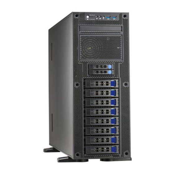
Page 23: About The Product
About the Product The following views show you the product. 1.5.1 System Front View http://www.tyan.com... - Page 24 STATE COLOR DESCRIPTION GREEN system is turn on Power LED GREEN system is under S1 or S3 state power off Blinking GREEN LAN active NIC1 GREEN LAN linked LAN not linked Blinking GREEN LAN active NIC2 GREEN LAN linked http://www.tyan.com...
- Page 25 Users from remote ID(UID) site could also activate ID LED by input a few commands in IPMI, detailed software support please visit http://www.tyan.com for latest AST2500 user guide. Press to reset the system. HDD LED Definitions...
-
Page 26: System Rear View
1.5.2 System Rear View B8030F65TV8E2H-2T-N RJ45 LAN Port#1(LAN1) ID Button Dedicated IPMI RJ45 LAN Port#5(LAN5) USB3.1 Portx2 VGA Port COM Port RJ45 LAN Port#4(LAN4) RJ45 LAN Port#3(LAN3) Rear Fans RJ45 LAN Port#2(LAN2) http://www.tyan.com... - Page 27 B8030F65TV8E2H-N Dedicated IPMI RJ45 LAN Port#3(LAN3) ID Button VGA Port USB3.1 Portx2 RJ45 LAN Port#2(LAN2) COM Port Rear Fans RJ45 LAN Port#1(LAN1) http://www.tyan.com...
- Page 28 B8030F65TV8E2H-G Dedicated IPMI RJ45 LAN Port#3(LAN3) ID Button VGA Port USB3.1 Portx2 RJ45 LAN Port#2(LAN2) COM Port Expansion Slots RJ45 LAN Port#1(LAN1) http://www.tyan.com...
- Page 29 ID LED will light blue if the system is identified. Users from remote sites can also activate the ID LED by entering a few commands in IPMI. For detailed software support, please visit http://www.tyan.com for the latest AST2500 user guide.
- Page 30 The system total output power limit varies in accordance with PSU redundancy and AC input range. Please refer to the following table for details. AC input 100-240V~ 15-12A 60-50Hz DC Output +3.3V +12V -12V +5Vsb Max Output Current 166.6A 0.3A Max Combined 150W 2000W Power 2000W@200-240Vac Total Power 1500@115-200Vac 1200@100-115Vac http://www.tyan.com...
-
Page 31: System Top View
Reserved space for slim CD dummy Power supply Reserved space for 2.5” HDD trays CPU Socket (2) 2.5”HDD trays Memory Slots (M1298T65-BP12E-2 HDD Backplane pre-installed) (8) 3.5”HDD trays FAN4 (M1309F65T-BP12-8 HDD Backplane pre-installed) FAN5 FAN1 IO Ports(with 5 LAN) FAN2 http://www.tyan.com... - Page 32 FAN2 pre-installed Reserved space for slim CD dummy FAN3 Reserved space for 2.5” HDD trays Power supply (2) 2.5”HDD trays M7129F83A-L16 Riser (M1298T65-BP12E-2 HDD Card Backplane pre-installed) (8) 3.5”HDD trays Riser Bracket (M1309F65T-BP12-8 HDD Backplane pre-installed) Rear Fans FAN1 http://www.tyan.com...
- Page 33 Reserved space for slim CD dummy FAN3 Reserved space for 2.5” HDD trays Power supply (2) 2.5”HDD trays CPU Socket (M1298T65-BP12E-2 HDD Backplane pre-installed) (8) 3.5”HDD trays Memory Slots (M1309F65T-BP12-8 HDD Backplane pre-installed) IO Ports(with 3 LAN) FAN1 http://www.tyan.com...
-
Page 34: Chassis Dimensions
1.5.4 Chassis Dimensions http://www.tyan.com... -
Page 35: Board Image
1.5.5 Board Image S8030 This picture is representative of the latest board revision available at the time of publishing. The board you receive may not look exactly like the above picture. http://www.tyan.com... -
Page 36: Block Diagram
1.5.6 Block Diagram S8030 Block Diagram NOTE: Please refer to Tyan S8030 User Guide for more MB details. http://www.tyan.com... -
Page 37: Chapter 2: Setting Up
To avoid damaging the motherboard and associated components, do not use torque force greater than kgf/cm (4.35 ~ 6.09 lb/in) on each mounting screw for motherboard installation. Do not apply power to the board if it has been damaged. http://www.tyan.com... -
Page 38: Precautions
Working on a system that is connected to a power supply can be extremely dangerous. Follow the guidelines below to avoid damage to FT65T-B8030 or injury to yourself. Ground yourself properly before removing the top cover of the system. -
Page 39: Installing Motherboard Components
This section describes how to install components on to the motherboard, including CPUs, memory modules, SSD/HDD and PCI-E cards. 2.1.1 Removing the Chassis Cover Follow these instructions to remove the FT65T-B8030 chassis cover. Loosen one screw and two thumb screws to slide the top cover off. http://www.tyan.com... - Page 40 Unscrew the PCIE bracket as in the image. Disconnect the cables. Remove the bracket from the chassis. http://www.tyan.com...
- Page 41 NOTE: When installing the top cover, pay attention to the diagonal direction as Shown by the arrow can easily buckle the top cover. http://www.tyan.com...
-
Page 42: Installing The Cpu And Heatsink
The force frame will automatically eject after the captive screws are being released. By placing your both index fingers on the sides on the metal handle, pull to release the rail frame. Then lift the rail frame to its fully open position. http://www.tyan.com... - Page 43 Make sure to push the carrier frame with package towards the end of the rail frame until it clicks into place. Do not drop the carrier frame or touch the package pad to avoid component damage. Using your thumb and forefinger, remove the PnP cap by lifting it up vertically. http://www.tyan.com...
- Page 44 Close the force frame. Then use a T20 Torx screwdriver to tighten the screws to secure the force frame in a sequential order (123). Align and install the CPU heatsink onto the top of the CPU socket. http://www.tyan.com...
- Page 45 Connect the heatsink power cable to the mainboard connector. NOTE: Always check with the manufacturer of the heat sink & processor to ensure that the thermal interface material is compatible with the processor and meets the manufacturer’s warranty requirements. http://www.tyan.com...
-
Page 46: Installing The Expansion Cards
2.1.3 Installing the Expansion Cards Follow the instructions to install the expansion cards. Locate the PCI-E Gen.4 slots on the motherboard. Unscrew to take out the dummy brackets. Screw the GPU bracket to the GPU card. http://www.tyan.com... - Page 47 Insert the GPU card into the PCIE slot and screw the GPU card to the chassis. Connect the GPU Power cable. http://www.tyan.com...
- Page 48 Insert a Mini-SAS card to the riser card.(PCIE Gen.4 x8 signal recommend to use LAN card and SAS card.) Place the bracket to the chassis and connect the cables to the riser bracket. Secure the riser bracket to the chassis with 4 screws. http://www.tyan.com...
-
Page 49: Installing The Memory
Align the memory module with the slot. When inserted properly, the memory slot locking levers lock automatically onto the indentations at the ends of the module. Follow the recommended memory population table to install the other memory modules. http://www.tyan.com... - Page 50 2. Use paired memory installation for max performance. 3. Populate the same DIMM type in each channel, specifically - Use the same DIMM size - Use the same # of ranks per DIMM 4. Always install with CPU0 Socket first. http://www.tyan.com...
- Page 51 Memory Population Table Quantity of Memory Module Populated Single CPU Populated (CPU0) P0_UMC0_CH_A0 P0_UMC1_CH_B0 P0_UMC3_CH_C0 P0_UMC2_CH_D0 Recommended P0_UMC6_CH_E0 P0_UMC7_CH_F0 P0_UMC5_CH_G0 P0_UMC4_CH_H0 http://www.tyan.com...
-
Page 52: Installing Hard Drives
2.1.5 Installing Hard Drives The FT65T-B8030 can support up to eight (8) 3.5”/2.5” SSD/HDD,two (2) 2.5” NVMe HDD. Follow these instructions to install a hard drive. Warning!!! Always install the hard disk drive to the chassis after the chassis is secured on the rack. - Page 53 Place a 3.5"/2.5” SSD/HDD into the HDD tray. 3.5” HDD 2.5” SSD/HDD Turn over the HDD unit and secure the SSD/HDD using 4 HDD screws. Reinsert the HDD tray into the chassis and press the locking lever to secure the tray. Close the front bezel. http://www.tyan.com...
- Page 54 2.5” NVMe HDD Follow these instructions to install the 2.5” NVMe HDDs into the chassis. Press the locking lever latch and pull the locking lever open. Slide the HDD tray out. http://www.tyan.com...
- Page 55 When installing a 2.5” NVMe HDD, the tray must be push to the end and NOTE: then press down the lever locking the tray. If the tray is not pushed to the end and pull down the lever, the tray cannot be installed in the place. http://www.tyan.com...
-
Page 56: Rack Mounting
2.2.1 Installing the FT65T-B8030 chassis in a Rack Follow these instructions to mount the TYAN FT65T-B8030 into an industry standard 19” rack. NOTE: Before mounting the TYAN FT65T-B8030 in a rack, ensure that all internal components have been installed and that the unit has been fully tested. - Page 57 Screw the mounting ears to the FT65T-B8030 as shown using six M4-L5 screws (black). Left Right Press the latch to draw out the inner rails from each rail assembly. Install the inner sliding rail to each side of the server using four M4-L5 screws.
- Page 58 1. Attach the outer rail to the rack. Pull the latch open and align the square stud with the square hole on the rack rail. Please note that the square stud must be fully attached inside the square hole and then close the latch to lock. Rear http://www.tyan.com...
- Page 59 Front http://www.tyan.com...
-
Page 60: Rack Mounting The Server
2.2.2 Rack Mounting the Server Lift the unit and then insert the inner slide rails into the middle rails. Push the whole system in. http://www.tyan.com... -
Page 61: Removing The Server From Rack
Secure the mounting screw to the rack. 2.2.3 Removing the Server from Rack 1. Use a screw driver to unscrew the chassis. 2. Push the latch on both sides of the chassis simultaneously to pull the system out. http://www.tyan.com... - Page 62 3. Pull out the chassis half way to the lock position. Push the white locking tabs forwards to slide the chassis all out from the rack. Caution: Remove the server from the rack carefully. Must be done with at least 2 people. http://www.tyan.com...
-
Page 63: Chapter 3: Replacing Pre-Installed Components
This chapter explains how to replace the pre-installed components, including the S8030 Motherboard, M1713G24-FPB Front Panel Board, M1309F65T-BP12-8/ M1298T65-BP12E-2 HDD Backplane, M7129F83A-L16 Riser Card, System Fan and Power Supply Unit etc. 3.0.2 Disassembly Flowchart The following flowchart outlines the disassembly procedures. http://www.tyan.com... -
Page 64: Removing The Cover
Removing the Cover Before replacing any parts you must remove the chassis cover. Follow Section 2.1.1 Removing the Chassis Cover (page 39) to remove the cover of the FT65T-B8030. Replacing Motherboard Components Follow these instructions to replace motherboard components, including the motherboard. - Page 65 Unscrew the M7129F83A-L16 riser card to replace with a new one. Follow the steps described earlier in reverse to reinstall the riser card bracket. Riser Card Cable Connection: http://www.tyan.com...
-
Page 66: Pci-E Riser Cards Specification
3.2.2 PCI-E Riser Cards Specification Front View Rear View M7129F83A-L16 IO Bridge Board (2) Slim SAS Connector(J5/J6) Specifications (1) 2*2 Power Connector(PWR2) (1) PCIE Slot x16 (J3) http://www.tyan.com... -
Page 67: Replacing The System Fan
Replacing the System Fan Follow these instructions to replace the system fan. Take out the failed fans. Unscrew to replace a new fan. Prepare new fans and insert them into the fan cage. http://www.tyan.com... - Page 68 Replacing Rear Fans Follow these instructions to replace the system fan. Release two thumb screws with the screwdriver. Turn over the rear fan module. Disconnect the fans cables. http://www.tyan.com...
- Page 69 Follow the steps described earlier in reverse to reinstall a new fan. Tighten the thumb screws of rear fan module with a screwdriver after rear fans are replaced. Install a small piece of iron to block the loophole of the fan cable. http://www.tyan.com...
-
Page 70: Replacing The Hdd Backplane Board
Follow these instructions to replace the M1309F65T-BP12-8 HDD Backplane Board. Disconnect all cables attached to the HDD BP Board. Unscrew to take it out. Prepare a new HDD BP Board and reinstall it into the chassis following the steps in reverse. http://www.tyan.com... - Page 71 Follow these instructions to replace the M1298T65-BP12E-2 HDD Backplane Board. Disconnect all cables attached to the HDD BP Board. Unscrew to take it out. Prepare a new HDD BP Board and reinstall it into the chassis following the steps in reverse. http://www.tyan.com...
-
Page 72: Hdd Bp Board Features
Here shows the M1309F65T-BP12-8 HDD Backplane Board in details. Front view: Rear view: M1309F65T-BP12-8 HDD Backplane Board (2) Mini SAS HD Connectors (CN10/CN11) (1) FAN System Connector (J4) (8) SATA HDD Connector Specifications (CN2/CN3/CN4/CN5/CN6/CN7/CN8/CN9) (5) FAN Connectors (J8/J9/J10/J11/J12) (2) Power Connector (J6/J7) (1) SGPIO Debug Connector (J2) http://www.tyan.com... -
Page 73: Connector Pin Definitions
3.4.2 Connector Pin Definitions CN2/CN3/CN4/CN5/CN6/CN7/CN8/CN9: Pin Out (connector to SATA HD) DEFAULT DEFAULT SAS[0…7]_TX_DP0 SAS[0…7]_TX_DN0 SAS[0…7]_RX_DN0 SAS[0…7]_RX_DP0 VDD_5_RUN(PRECHARGE) VDD_5_RUN VDD_5_RUN PRSNTN[0…7] RDYLED[0…7] VDD_12_RUN(PRECHARGE) VDD_12_RUN VDD_12_RUN http://www.tyan.com... - Page 74 SAS[3/7]_TX_DP0 SAS[3/7]_RX_DP0 SAS[3/7_TX_DN0 SAS[3/7]_RX_DN0 J4: SYSTEM FAN connector (BP to MB) DEFAULT DEFAULT FAN_TACH1 FAN_TACH6 FAN_TACH2 FAN_TACH7 FAN_TACH3 FAN_TACH8 FAN_TACH4 FAN_TACH9 FAN_TACH5 FAN_TACH10 CON_PWM2 CON_PWM1 FAN_TACH11 BMC_FAN_SDA FAN_TACH12 BMC_FAN_SCL V3V3_AUX CON_PWM3 V3V3_AUX FAN_TACH13 FAN_TACH15 FAN_TACH14 FAN_TACH16 CON_PWM4 CON_PWM5 CON_PWM0 http://www.tyan.com...
- Page 75 J3: MODE SELECT1 Jump setup Header. (SGPIO Mode Intel/AMD) DEFAULT INTEL_AMD#_SEL 1_2 : INTEL MODE 2_3 : AMD MODE J5: I2C SETUP FROM Jump setup Header. (I2C setup from SAS/SYSTEM FAN connector) DEFAULT VCC_AUX CKB_SELECT 1_2 : BY SAS CONN 2_3 : BY SYSTEM FAN CONN http://www.tyan.com...
- Page 76 2_3: BY SAS03 CONN(CN11) J7: ATX Power connector. (Power supply to BP) DEFAULT DEFAULT VDD_12_RUN VDD_12_RUN VDD_12_RUN VDD_12_RUN J6: ATX Power connector. (Power supply to BP) DEFAULT DEFAULT VDD_12_FAN VDD_12_FAN VDD_12_FAN VDD_12_FAN J14: SATA HDD ACT LED OUT. DEFAULT HDD_BP_ACT_LED_OUT http://www.tyan.com...
- Page 77 4P Power CON (PW1) Header for PCA9544 SMBUS address Select (3PHD-1) The rear 2 SATA SSDs/HDDs (SATA0 & SATA1) are not available when AMD EPYC™ 7002/7003 Series Processors deployed in all configurations. Please contact Tyan Technical Support for more details. http://www.tyan.com...
-
Page 78: Replacing The Front Panel Board
Slide the LED control board unit out of the chassis. Disconnect the cables and remove three screws securing the mylar and LED control board to the bracket. After replacement, insert the unit into the chassis following the above procedures in reverse. http://www.tyan.com... -
Page 79: Front Panel Board Features
15*2 Header connect to MB (2) USB3.0 connector LEDs 1 GREEN/BLUE LED for LAN1 and ID 1 GREEN/GREEN LED for LAN2 and HDD 1 GREEN/AMBER LED for LAN3 and BMC 1 power LED Board size 97*45.2MM http://www.tyan.com... -
Page 80: Pin Definition
FP_USB3_RX_P0 FP_USB3_TX_N0 FP_USB3_TX_P0 USB0- USB0+ USB1+ USB1- FP_USB3_TX_P1 FP_USB3_TX_N1 FP_USB3_RX_P1 FP_USB3_RX_N1 VCC_USB J3: 15*2 Header Definition Definition PW_LED+ ID_LED+ PW_LED- ID_LED- HDD_LED+ SYS_FAULT1- HDD_LED- SYS_FAULT2- PWR_SW- LAN1_LED+ LAN1_LED- RESET- ICH_SMBDAT ICH_SMBCLK ID_SW- INTRU# TEMP_SENSOR LAN2_LED+ NMI_SW LAN2_LED- LAN3_LED+ LAN3_LED- http://www.tyan.com... -
Page 81: Replacing The Power Supply
The system has one pre-installed Power Supply Units. Please unplug the power cord before you follow these instructions to replace the power supply units. Disconnect the power supply cable. Unscrew to release the power supply unit. Unscrew to release the power supply unit. http://www.tyan.com... - Page 82 Take out the power supply unit. To replace a new power supply. And follow the procedures in reverse order to install a new power supply. http://www.tyan.com...
- Page 83 Power supply Unit GPU PWR Connection http://www.tyan.com...
- Page 84 http://www.tyan.com...
- Page 85 http://www.tyan.com...
-
Page 86: Removing The Motherboard
Refer to the sections described earlier to remove all cables and components on the motherboard. Unscrew the motherboard. Carefully lift the motherboard from the chassis. Prepare a new motherboard and follow the steps described earlier in reverse order to reinstall the motherboard into the chassis. http://www.tyan.com... - Page 87 NOTE http://www.tyan.com...
-
Page 88: Appendix I: How To Recover Uefi Bios
UEFI recovery bootloader that would prevent the recovery process itself from working. In no event shall Tyan be liable for direct, indirect, incidental, special or consequential damages arising from the BIOS update or recovery. - Page 89 “Flash update completed. Press any key to reset the system” displayed on screen. Remove the USB disk and reboot. If your system does not have video output or the POST code halts at “FF” on the right-lower portion of the screen, please contact Tyan representatives for RMA service. http://www.tyan.com...
-
Page 90: Appendix Ii: Cable Connection Tables
Slim-SAS Cable 7P → HDR1 P/N: 422T60900011 → SATA Cable-1 SATA0 P/N: 422T53400008 → SATA Cable-2 SATA1 P/N: 422T53400008 4. Slim-SAS to Slim-SAS(2) Cable M7129F83A-L16 to S8030 MB M7129F83A-L16 Connect to S8030 M/B → Slim-SAS Cable J5 & J6 P/N: 422T63200005 http://www.tyan.com... - Page 91 PSU to M1298T65-BP12E-2 Connect to M1298T65-BP12E-2 → 4P PWR Cable P21 8. 2x2P PWR Cable PSU to M7129F83A-L16 Connect to FP ctrl M7129F83A-L16 cable → FP ctrl cable 2x2P to FP ctrl cable 2x2P 2x2P PWR Cable P22 M7129 PW2 Conn http://www.tyan.com...
- Page 92 9. System & Rear FAN extend Cable System & Rear FAN to M1309F65T-BP12-8 Connect to M1309F65T-BP12-8 → System FAN1 → System FAN2 → System FAN3 Real FAN4 → (Need to FAN extend P/N: 422T63200006 cable) Real FAN5 → (Need to FAN extend P/N: 422T63200006 cable) http://www.tyan.com...
-
Page 93: Appendix Iii: Fan And Temp Sensors
The red spot indicates the sensor. Fan and Temp Sensor Location: Fan Sensor: It is located in the third pin of the fan connector, which detects the fan speed (rpm) Temp Sensor: refer to Figure 1: Sensor Location. They detect the system temperature around. http://www.tyan.com... - Page 94 BIOS Temp Sensor Name Explanation: http://www.tyan.com...
- Page 95 Temperature of CPU0 DIMM Channel G P0_UMC4_CH_H Temperature of CPU0 DIMM Channel H CPU_FAN Fan Speed of CPU_FAN SYS_FAN_1 Fan Speed of SYS_FAN_1 SYS_FAN_2 Fan Speed of SYS_FAN_2 SYS_FAN_3 Fan Speed of SYS_FAN_3 SYS_FAN_4 Fan Speed of SYS_FAN_4 SYS_FAN_5 Fan Speed of SYS_FAN_5 http://www.tyan.com...
- Page 96 Fan Speed of SYS_FAN_10 SYS_FAN_11 Fan Speed of SYS_FAN_11 SYS_FAN_12 Fan Speed of SYS_FAN_12 PSU0_STATUS Current status of PSU0 PSU0_Temp Temperature of PSU0 PSU0_FAN Fan Speed of PSU0 PSU1_STATUS Current status of PSU1 PSU1_Temp Temperature of PSU1 PSU1_FAN Fan Speed of PSU1 http://www.tyan.com...
-
Page 97: Appendix Iv: Fru Parts Table
FRU-TH-0400 336210000065 80*80*38mm,4 PIN module Riser FRU-RC-1260 411T62700036 M7129F83A-L16,R01 board rack FT65T-B8030 SLIDE RAIL KIT+HANDLE mount FRU-AS-9230 5412T6320006 FRU kit R+HANDLE L 550 mm,SlimSAS 8i to 2*SlimSAS 8i FRU-CS-1790 422T63200005 CABLE,SlimSAS 8i 74P/2*SlimSAS 8i 74P 350 mm,MINI-SAS HD CABLE, SHORT... - Page 98 NOTE http://www.tyan.com...
-
Page 99: Appendix Vi: Technical Support
MITAC serves multiple market segments with the industry’s most competitive services to support them. Please feel free to contact us directly for this service at tech-support@tyan.com Help Resources: 1. See the beep codes section of this manual. - Page 100 (RMA) number. The RMA number should be prominently displayed on the outside of the shipping carton and the package should be mailed prepaid. TYAN will pay to have the board shipped back to you. TYAN® FT65T-B8030 Service Engineer’s Manual V1.0 D2514 - 100 Document No.:...
Need help?
Do you have a question about the FT65T-B8030 and is the answer not in the manual?
Questions and answers