Table of Contents
Advertisement
Quick Links
Advertisement
Table of Contents

Related Manuals for TYAN GT24E-B5556


Summary of Contents for TYAN GT24E-B5556
- Page 1 GT24E-B5556 Service Engineer’s Manual http://www.tyan.com...
- Page 2 MITAC assumes no liability whatsoever, and ® disclaims any express or implied warranty, relating to sale and/or use of TYAN products including liability or warranties relating to fitness for a particular purpose or merchantability. MITAC retains the right to make changes to produce descriptions and/or specifications at any time, without notice.
- Page 3 This Class A digital apparatus complies with Canadian ICES-003. Cet appareil numérique de la Classe A est conforme à la norme NMB-003 du Canada. Notice for Europe (CE Mark) ● This product is in conformity with the Council Directive 2014/30/EU and 2014/35/EU. http://www.tyan.com...
- Page 4 Replace only with the same or equivalent type recommended by manufacturer. Dispose of used battery according to manufacturer instructions and in accordance with your local regulations. VCCI-A ● この装置は、クラスA機器です。この装置を住宅環境で使用すると電波妨害を引き 起こすことがあります。この場合には使用者が適切な対策を講ずるよう要求される VCCI-A ことがあります。 Safety: IEC/EN 62368-1 ● This equipment is compliant with CB/LVD of Safety: IEC/EN 62368-1. http://www.tyan.com...
- Page 5 About this Manual This manual is intended for skill person with hardware knowledge of computers. It is aimed to provide you with instructions on installing your TYAN GT24E-B5556. How this guide is organized This guide contains the following parts: Chapter 1: Overview...
- Page 6 Safety and Compliance Information Before installing and using TYAN GT24E-B5556, take note of the following precautions: ·Read all instructions carefully. ·Do not place the unit on an unstable surface, cart, or stand. ·Do not block the slots and opening on the unit, which are provided for ventilation.
- Page 7 You must become familiar with the safety information in this guide before you install, operate, or service TYAN products. Symbols on Equipment Caution. This symbol indicates a potential hazard. The potential for injury exists if cautions are not observed.
- Page 8 · Do not attempt to move a rack by yourself; a minimum of two people are needed to move a rack. · Do not attempt to move a fully loaded rack. Remove equipment from the http://www.tyan.com...
- Page 9 · Verify that the AC power supply branch circuit that provides power to the rack is not overloaded. This will reduce the risk of personal injury, fire, or damage to the equipment. The total rack load should not exceed 80 percent http://www.tyan.com...
- Page 10 · Dispose of used batteries according to the instructions of the manufacturer. Do not dispose of batteries with the general household waste. To forward them to recycling or proper disposal, use the public collection system or return them to TYAN, your authorized TYAN partner, or their agents. http://www.tyan.com...
- Page 11 Equipment Modifications · Do not make mechanical modifications to the system. TYAN is not responsible for the regulatory compliance of TYAN equipment that has been modified. Equipment Repairs and Servicing · The installation of internal options and routine maintenance and service of...
- Page 12 http://www.tyan.com...
-
Page 13: Table Of Contents
Table of Contents Chapter 1: Overview............... 17 About the TYAN GT24E-B5556 ..........17 Product Model ................ 17 Features .................. 18 Standard Parts List ..............25 1.4.1 Box Contents ..............25 About the Product ..............26 ... - Page 14 5.3.15 Hardware Health Configuration ........145 Chipset Menu ............... 148 5.4.1 North Bridge Configuration ..........149 5.4.2 South Bridge Configuration ........... 156 Server Management ............. 160 5.5.1 System Event Log ............162 http://www.tyan.com...
- Page 15 AMIBIOS Post Code (Aptio) ..........182 Appendix I: Cable Connection Tables ........189 Appendix II: Fan and Temp Sensors .......... 193 Appendix III: FRU Parts Table ............. 197 Appendix IV: Technical Support ..........199 http://www.tyan.com...
- Page 16 http://www.tyan.com...
-
Page 17: Chapter 1: Overview
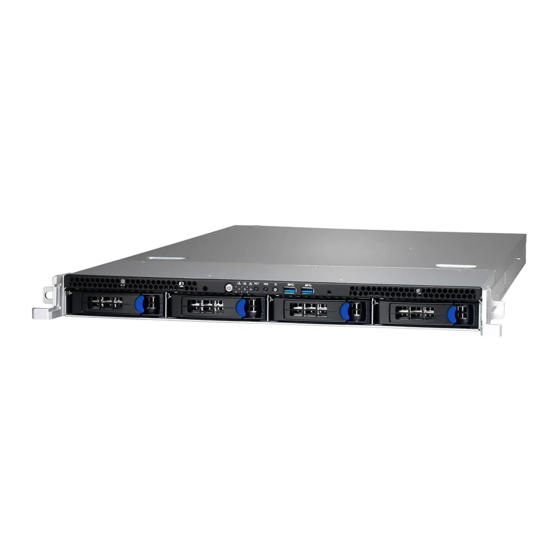
® TYAN ’s latest chassis, featuring a robust structure and a solid mechanical enclosure. All of this provides GT24E-B5556 the power and flexibility to meet the needs of nowadays server application. Product Model The system boards within the Tyan barebone systems contain different features and chipsets, which are defined by the following models: B5556G24EV4HR-2T: Intel-based platform, support (4) hot-swap 2.5”/3.5”... -
Page 18: Features
Features GT24E-B5556 (B5556G24EV4HR-2T) Form Factor 1U Rackmount Chassis Model GT24E Dimension (D x W x 25.4" x 17.2" x 1.72" (645 x 436 x 43.6mm) System Motherboard Name S5556GM2NR-2T Gross Weight 21 kg (46.5 lbs) Net weight 15.5 kg (34.5 lbs) - Page 19 (2) PCI-E Gen3 x8 slots (HH / HL) * split by Mux. Expansion Slots (1) M7081-R8-1L riser card for (1) PCI-E Gen3 x8 slot , Pre-install TYAN M5556-L16-2F riser card for (1) Riser Card FH/FL PCI-E Gen3 x16 slot or (2) FH/FL PCI-E Gen3 x8 slots...
- Page 20 Hardware Monitor, PXE boot support, ACPI sleeping states S5, User BIOS Feature Configurable FAN PWM Duty Cycle, Console Redirection, ACPI 6.1, SMBIOS 3.1/PnP/Wake on LAN Please refer to our AVL support Operating System OS supported list lists. Regulation FCC (SDoC) Class A http://www.tyan.com...
- Page 21 - 40° C ~ 70° C (-40° F ~ 158° F) Operating Environment In/Non-operating 90%, non-condensing at 35° C Humidity RoHS RoHS 6/6 Compliant Barebone (1) GT24E-B5556 Barebone Package Contains Manual (1) Quick Installation Guide GT24E-B5556 (B5556G24EV4HR-2T-N) Form Factor 1U Rackmount Chassis Model...
- Page 22 (2) PCI-E Gen3 x8 slots (HH / HL) * split by Mux. (2) 10GbE ports, Q'ty / Port (1) GbE port dedicated for IPMI Controller Intel X550-AT2 Realtek RTL8211E Connector (2) SATA-DOM Storage SATA Controller Intel C242 Speed 6.0 Gb/s http://www.tyan.com...
- Page 23 Supports storage over Feature IP and remote platform-flash, USB Server Management 2.0 virtual hub IPMI 2.0 compliant baseboard AST2500 IPMI management controller (BMC), Feature 10/100/1000 Mb/s MAC interface Brand / ROM size AMI, 32MB BIOS Feature Hardware Monitor, PXE boot support, http://www.tyan.com...
- Page 24 In/Non-operating 90%, non-condensing at 35° C Humidity RoHS RoHS 6/6 Compliant Barebone (1) GT24E-B5556 Barebone Package Contains Manual (1) Quick Installation Guide NOTE: 1. The specifications are subject to change without prior notice. 2. Please visit our Web site for the latest information.
-
Page 25: Standard Parts List
Standard Parts List This section describes GT24E-B5556 package contents and accessories. Open the box carefully and ensure that all components are present and undamaged. The product should arrive with packaged as illustrated below. 1.4.1 Box Contents If any items are missing or appear damaged, contact your retailer or browse to TYAN’s website for service:... -
Page 26: About The Product
M1713G24-FPB Front Panel Board M1713G24-FPB Front Panel Board Power Button with green LED ID LED LAN3 LED (no function) Reset Button LAN2 LED NMI Button LAN1 LED ID Button Warning LED USB3.1 Gen1 Port 2 HDD LED USB3.1 Gen1 Port 1 http://www.tyan.com... - Page 27 Link / Solid on Green No Function LAN3 LED HDD LED State Color Description Solid On Drive present, no activity Activity LED Green Blinking Drive present, with activity Solid On HDD Failed Status LED Blinking @1Hz Identify Blinking @4Hz Rebuild http://www.tyan.com...
-
Page 28: System Rear View
System Rear View PSU1 PSU0 LAN3 (dedicated IPMI support for BMC) USB3.1 Gen2 Ports VGA Port Serial Port LAN2 LAN1 Low-profile expansion card area (PCIE #03) ID LED (blue) Full-height/full-length expansion card area (PCIE #01) Full-height/full-length expansion card area (PCIE #02) http://www.tyan.com... - Page 29 ID LED will light blue if the system is identified. Users from remote sites can also activate the ID LED by entering a few commands in IPMI. For detailed software support, please visit http://www.tyan.com for the latest AST2500 user guide.
- Page 30 Green Solid On Link 10 Mbps Green Blinking Active Green Solid On Green Solid On Link 100 Mbps Green Blinking Green Solid On Active Green Solid On Amber Solid On Link 1000 Mbps Green Blinking Amber Solid On (1Gbps) Active http://www.tyan.com...
-
Page 31: System Top View
1.5.3 System Top View B5556G24EV4HR-2T-N Internal SSD Sequence http://www.tyan.com... - Page 32 B5556G24EV4HR-2T Hot-swap HDD trays PSU1 M1283G24-BP12E-4 PSU0 HDD Backplane Board Riser Card Bracket System fans (M7081-R8-1L pre-installed) M1620G24E-D-PDB Riser Card Bracket Power Distribution Board (M5556-L16-2F pre-installed) http://www.tyan.com...
-
Page 33: Chassis Dimensions
1.5.4 Chassis Dimensions http://www.tyan.com... - Page 34 NOTE http://www.tyan.com...
-
Page 35: Chapter 2: Setting Up
Caution! To avoid damaging the motherboard and associated components, use torque force within the range kgf/cm (4.35 ~ 6.09 lb/in) on each mounting screw for motherboard installation. Do not apply power to the board if it has been damaged. http://www.tyan.com... -
Page 36: Precautions
Working on a system that is connected to a power supply can be extremely dangerous. Follow the guidelines below to avoid damage to GT24E-B5556 or injury to yourself. Ground yourself properly before removing the top cover of the system. -
Page 37: Installing Motherboard Components
CPUs, memory modules and add on cards. 2.1.1 Removing the Chassis Cover Follow these instructions to remove GT24E-B5556 chassis cover. Loosen the thumb screw and the screw on the right side. Slide to lift the rear top cover up. http://www.tyan.com... - Page 38 http://www.tyan.com...
-
Page 39: Replacing The Chassis Cover
2.1.2 Replacing the Chassis Cover Follow these instructions to replace the GT24E-B5556 top chassis cover. Place the top cover onto the chassis and slide the top cover into place. Tighten the thumbscrew. NOTE: The thumbscrew should be tightened with a screwdriver after the top chassis are closed. -
Page 40: Installing The Cpu, Heatsink And Air Duct
2.1.3 Installing the CPU, Heatsink and Air Duct Follow the steps below to install the processor, heatsink and air duct. Take out the protection cap. Open the socket lever to lift up the socket cover. http://www.tyan.com... - Page 41 http://www.tyan.com...
- Page 42 Install the processor and make sure the gold arrow is located in the right direction. Close the socket cover. Close the socket lever. http://www.tyan.com...
- Page 43 The thermal grease has been applied to the bottom of the heatsink. Align and install the alignment tab on the air duct underneath the fan bracket on the chassis. Make sure the air flow direction is correct. Secure the air duct to the chassis with two screws. http://www.tyan.com...
-
Page 44: Installing The Memory
Align the memory module with the slot. When inserted properly, the memory slot locking levers lock automatically onto the indentations at the ends of the module. Follow the recommended memory population table to install the other memory modules. http://www.tyan.com... - Page 45 1. Supported DDR4 (ECC and Non-ECC) UDIMM. 2. The memory slots of DDR4 channels should be populated on a farthest first fashion. This means that blue connector cannot be populated if black is empty. 3. indicates a populated DIMM slot. http://www.tyan.com...
-
Page 46: Installing The Pci-E Card
2.1.5 Installing the PCI-E Card Follow these instructions to install the PCI-E card. 1. Unscrew the riser card bracket. 2. Remove the riser card bracket from the chassis. 3. Unscrew to remove the dummy bracket. http://www.tyan.com... - Page 47 4. Insert the PCI-E card into the riser card bracket and screw it firmly. 5. Reposition and screw the riser card bracket into the chassis. http://www.tyan.com...
-
Page 48: Installing The Gpu Card
2.1.6 Installing the GPU Card Follow these instructions to install the GPU card. Loosen 6 screws to lift up the GPU riser card bracket. Unscrew to remove both dummy brackets. http://www.tyan.com... - Page 49 Insert the GPU card into the GPU riser card bracket and screw it firmly. Making sure the alignment tabs are properly aligned, install the GPU air duct on the GPU riser card bracket and secure the GPU air duct to the GPU card with two screws. http://www.tyan.com...
- Page 50 Turn the GPU riser card bracket over and use four screws to secure the GPU card to the riser bracket. Connect the GPU cable. Reinsert the GPU riser card bracket into the chassis and secure with 6 screws. http://www.tyan.com...
-
Page 51: Installing Hard Drives
2.1.7 Installing Hard Drives The GT24E-B5556 supports four 3.5”/2.5” hot-swap HDD/SSD and two 2.5” internal SSD. Installing 3.5” Hot-Swap Hard Drives Follow these instructions to install a 3.5” HDD. Warning!!! Always install the hard disk drive to the chassis after the chassis has been secured on the rack. - Page 52 Place the 3.5” hard disk drive into the HDD tray and secure the HDD to the HDD tray using 4 screws. Reinsert the HDD tray into the chassis. Push to secure the locking lever until it clicks into place. http://www.tyan.com...
- Page 53 Always install the hard disk drive to the chassis after the chassis has been secured on the rack. Press the locking lever latch and pull the locking lever open. Slide the HDD tray out. Place the 2.5” HDD/SSD into the HDD tray and align the 2.5” HDD/SSD with its guide pins. http://www.tyan.com...
- Page 54 Turn over the HDD tray and secure the HDD/SSD to the tray using 4 screws. Reinsert the HDD tray into the chassis. Push to secure the locking lever until it clicks into place. http://www.tyan.com...
- Page 55 Installing 2.5” Internal Hard Drives Follow these instructions to install a 2.5” SSD. Warning!!! Always install the hard disk drive to the chassis after the chassis has been secured on the rack. Unscrew the front top cover to lift it up. http://www.tyan.com...
- Page 56 Remove the paper tapes. Connect the SATA and power cables. Align the 2.5” SSD with guide pins and slightly pull to place it in. http://www.tyan.com...
- Page 57 http://www.tyan.com...
-
Page 58: Rack Mounting
19" rack. NOTE: Before mounting the TYAN GT24E-B5556 in a rack, ensure that all internal components have been installed and that the unit has been fully tested. However, to make the installation easier, we suggest that you remove all HDD trays before you insert the chassis into the rack. - Page 59 Installing the Inner Rails to the Chassis Screw the mounting ears to each side of the GT24E-B5556 as shown using four screws from the supplied mounting ears screw pack. Draw out the inner rail from the rail assembly. When the rail comes to a stop pull the tab to release the latch and completely draw the inner rail out.
- Page 60 Secure the inner sliding rail to the server using one M4 x 4L screw (B). Repeat steps 2 to 4 to secure the sliding rail to the other side of the server. http://www.tyan.com...
- Page 61 Secure the outer rails to the rack using four M5 screws and four washers (A) on each side. Rack Mounting the Server Draw out the middle rail to the latch position. Lift the unit and then insert the inner slide rails into the middle rails. http://www.tyan.com...
- Page 62 When the inner rails come to a stop, pull the tab to release the latch and push the whole system in. Secure the mounting ears of the unit to the rack using two M5 x 20L screws (C). http://www.tyan.com...
-
Page 63: Chapter 3: Replacing Pre-Installed Components
This chapter explains how to replace the pre-installed components, including the Motherboard, M1713-G24-FPB Front Panel Board, M1283G24-BP12E-4 Backplane, M1620G24E-D-PDB Power Distribution board, M7081-R8-1L M5556-L16-2F Riser cards, System fan and Power supply unit etc. Disassembly Flowchart The following flowchart outlines the disassembly procedure. http://www.tyan.com... -
Page 64: Removing The Cover
Removing the Cover Before replacing any parts you must remove the chassis cover first. Follow Chapter 2.1.1 to remove the cover of the GT24E-B5556. Replacing Motherboard Components Follow these instructions to replace motherboard components, including the motherboard. 3.4.1 Replacing the M7081-R8-1L Riser Card... - Page 65 3.4.1.1 M7081-R8-1L Riser Card Features Form Factor Dimension: 30mmx106.27mm Specifications (1) PCI-E x8 Gen3 http://www.tyan.com...
-
Page 66: Replacing The M5556-L16-2F Riser Card
Follow these instructions to replace the M5556-L16-2F Riser card. Loosen 6 screws to lift up the GPU card bracket. Unscrew the M5556-L16-2F riser card to replace with a new one. Follow the steps described earlier in reverse to reinstall the riser card bracket. http://www.tyan.com... - Page 67 Dimension: 31.64mm x 255mm (1) PCI-E x16 Gen3 Slot (J4) Specifications (1) PCI-E x8 Gen3 Slot (J5) (1) PCIE PCIE Config Jumper (J25) NOTE: (1) PCIE PCI-E configured DESIGN NOTE SLOT STATUS Pin 1-2 closed Disable Pin 2-3 closed http://www.tyan.com...
-
Page 68: Replacing The Front Panel Board
3.4.3 Replacing the Front Panel Board Follow these instructions to replace the M1713G24-FPB Front Panel Board. Unscrew to lift up the front top cover. http://www.tyan.com... - Page 69 Remove the rubber stubs securing the mylar to the Front Panel Board. Lift the front panel board free from the mylar. Replace the Front Panel Board as shown below. After replacing the front panel board, insert the Front Panel Board into the chassis following the above procedures in reverse. http://www.tyan.com...
- Page 70 (1) 10x2 pin USB3.0 Header connected to MB Specifications (1) 15x2 pin Header connected to MB (2) USB3.1 Gen1 Connector (1) Green/Blue LED for LAN1 and ID (1) Green/Green LED for LAN2 and HDD LEDs (1) Green/Amber LED for LAN3 and BMC (1) Power LED http://www.tyan.com...
- Page 71 FP_USB3_RX_P0 FP_USB3_TX_P1 FP_USB3_TX_N0 FP-USB3_TX_N1 FP_USB3_TX_P0 FP_USB3_RX_P1 USB0- FP_USB3_RX_N1 USB0+ VCC_USB J3: Front Panel Board Connector Definition Definition PW_LED+ ICH_SMBDAT ICH_SMBCLK ID_LED+ ID_SW- PW_LED- INTRU# ID_LED- TEMP_SENSOR HDD_LED+ LAN2_LED+ SYS_FAULT1- NMI_SW HDD_LED- LAN2_LED- SYS_FAULT2- PWR_SW- LAN1_LED+ LAN3_LED+ LAN3_LED- LAN1_LED- RESET- http://www.tyan.com...
-
Page 72: Replacing The System Fan
3.4.4 Replacing the System Fan Follow these instructions to replace the fan. Disconnect the fan cable. Take out the fan from the chassis. Release the rubber screws from the fan. http://www.tyan.com... - Page 73 Release the rubber screws and the push pins from the fan. Replace the failed fan module with a new one. Follow the procedures described earlier in reverse order to reinstall. http://www.tyan.com...
-
Page 74: Replacing The Hdd Backplane Board
Before detach the HDD backplane, please remove all the HDD trays with HDDs, otherwise the HDD backplane will be damage when strains at the disassembly. Remove all fans. Disconnect all cables connected to the M1283G24-BP12E-4 HDD Backplane. Unscrew to lift up the HDD BP Board Bracket. http://www.tyan.com... - Page 75 The HDD BP Board bracket is as shown below. Unscrew to remove the BP mylar and replace with a new HDD backplane board. Follow the procedures described earlier to reinstall the HDD backplane board bracket into the chassis. http://www.tyan.com...
- Page 76 3.4.5.1 HDD Backplane Board Features Front View Rear View Form Factor Dimension: 422.4*29.8mm 1 OCuLink x8 Connector Input 1 Mini SAS Connector Input Specifications Overview 4 SATA HDD/SSD or 2 SATA HDD/SSD + 2 NVMe Output 6 FAN connector http://www.tyan.com...
- Page 77 SATA + NVMe Connector HDD2 SATA Connector HDD3 SATA Connector SATA0_3 Mini SAS Connector NVMe01 OCU Link Connector Power Connector Power Connector FAN1 FAN Connector FAN2 FAN Connector FAN3 FAN Connector FAN4 FAN Connector FAN5 FAN Connector FAN6 FAN Connector http://www.tyan.com...
-
Page 78: Replacing The Power Distribution Board
Board in your system. Disconnect all cables connected to the power distribution board. Unscrew to take off the power distribution board and replace with a new one. Insert the PDB into the chassis following the above procedures in reverse. http://www.tyan.com... - Page 79 Power Distribution Board Features 3.4.6.2 Connector Definitions Definition Location Power Supply slot Power Supply slot PWR1 ATX Power 12x2 ATX Power 4x2 ATX Power 4x2 HDD Power 4x1 HDD Power 4x1 PM Bus DOM_5V_PW1 DOM Power DOM_5V_PW2 DOM Power http://www.tyan.com...
-
Page 80: Replacing The Power Supply
Follow these instructions to replace the power supply module in your system. Press the latch to pull the power supply out. After replacing a new power supply, press and hold the latch to push the power supply back into the chassis. http://www.tyan.com... -
Page 81: Disconnecting All Motherboard Cables
3.4.8 Disconnecting All Motherboard Cables Disconnect all cables connected to the motherboard. http://www.tyan.com... -
Page 82: Removing The Motherboard
After removing all of the aforementioned cables, follow the instructions below to remove the motherboard from the chassis. Remove the air duct, processor and heatsink if installed. Remove six screws securing the motherboard to the chassis. Carefully lift the motherboard from the chassis. http://www.tyan.com... -
Page 83: Chapter 4: Motherboard Information
Caution! To avoid damaging the motherboard and associated components, use torque force within the range kgf/cm (4.35 ~ 6.09 lb/in) on each mounting screw for motherboard installation. Do not apply power to the board if it has been damaged. http://www.tyan.com... -
Page 84: Board Image
Board Image S5556 This picture is representative of the latest board revision available at the time of publishing. The board you receive may not look exactly like the above picture. http://www.tyan.com... -
Page 85: Block Diagram (S5556)
Block Diagram (S5556) http://www.tyan.com... -
Page 86: Motherboard Mechanical Drawing
Motherboard Mechanical Drawing http://www.tyan.com... -
Page 87: Board Parts, Jumpers And Connectors
The board you receive may not look exactly like the above diagram. The DIMM slot numbers shown above can be used as a reference when reviewing the DIMM population guidelines shown later in the manual. For the latest board revision, please visit our web site at http://www.tyan.com. http://www.tyan.com... - Page 88 22. 5Px2 SGPIO Header (J24) 11. 4p FAN Connector (J38) 23. 4P_IPMB Header (J31) 12. 4p FAN Connector (J34) Jumpers ME FIRMWARE UPDATE (J10) PSU Alert Function (J105) CMOS CLEAR JUMPER (J12) CPU PCI-E CONFIG (J43) FLASH SECURITY OVERRIDE (J106) http://www.tyan.com...
- Page 89 GRN / SYSTEM1 RST LED (LED6) RED / DIMM Error (LED3) RED / PSMI_ALERT_LED RED / DIMM Error (LED4) ID LED (SW1) RED / DIMM Error (LED7) Jumper Legend OPEN - Jumper OFF Without jumper cover CLOSED - Jumper ON With jumper cover http://www.tyan.com...
- Page 90 J32: Front Panel Header Signal Signal PW_LED+ FP_PWR ID_LED+ PWR_LED- ID_LED- HDD_LED+ FAULT_LED1- HDD_LED- FAULT_LED2- PWR_SW# LAN1 ACTLED+ LAN1 ACTLED- RST_SW# SMBus SDA SMBus SCL SYS_ID_SW# INTRUSION# TEMP SENSOR LAN2 ACTLED+ NMI_SW# LAN2 ACTLED- J36: PSMI Connector Signal Signal PSMI_CLK PSMI_DAT PSMI_ALERT http://www.tyan.com...
- Page 91 ATA ready drives via the Serial ATA cable. Rx_DN J16: SATA0/SATADOM1 Rx_DP J19: SATA1/SATADOM2 VCC (P5V) J74: USB3.1 Gen1 Header Signal Signal VCC (P5V) USB3.1_P1_RX_DN VCC (P5V) USB3.1_P1_RX_DP USB3.1_P2_RX_DN USB3.1_P2_RX_DP USB31_P1_TX_DN USB31_P1_TX_DP USB31_P2_TX_DN USB31_P2_TX_DP USB2.0_PA_DN USB2.0_PA_DP USB2.0_PB_DN OC_N ( NI ) USB2.0_PB_DP http://www.tyan.com...
- Page 92 5. Reconnect power connectors to the motherboard and power on Clear CMOS system. J10: ME Firmware Update Jumper Pin1-2 closed: Normal (Default) Pin2-3 closed: ME Force Update J106: Flash Security Override Jumper Pin1-2 closed: Flash Security Override Disable (Default) Pin2-3 closed: Flash Security Override Enable http://www.tyan.com...
- Page 93 +3.3 Vdc -12 Vdc +5 Vdc PS_ON# +5 Vdc PWR_OK 5 VSB +5 Vdc +12 Vdc +5 Vdc +12 Vdc +5 Vdc +3.3 Vdc PW2: CPU and Memory Power Connector Signal Signal +12 Vdc +12 Vdc +12 Vdc +12 Vdc http://www.tyan.com...
-
Page 94: Mainboard Led Definitions
Signal +3V_AUX State Description BMC_HW_HEARTBRAT The LED shuts off when the BMC LED6 / GRN controller cannot be detected or properly initiated. The LED blinks per second to Blinking Green indicate that the BMC controller is working normally http://www.tyan.com... - Page 95 Blinking indicate that the DIMM cannot be detected or operly initiated. Signal + VCC3_AUX State Description LED5 PSU Alert LED The LED shuts off when the PSU is normal. The LED lights up when the PSU is Green abnormally. http://www.tyan.com...
- Page 96 The LED lights up when the power of Green CPU is normally. Signal + 3V SYSTEM2 State Description LED12 RST LED The LED shuts off when the power of system is abnormal. The LED lights up when the power of Green system is normally. http://www.tyan.com...
-
Page 97: Thermal Interface Material
CPU lid (applying too much will actually reduce the cooling). NOTE: Always check with the manufacturer of the heat sink & processor to ensure that the thermal interface material is compatible with the processor and meets the manufacturer’s warranty requirements. http://www.tyan.com... -
Page 98: Tips On Installing Motherboard In Chassis
Be especially careful to look for extra stand-offs. If there are any stand-offs present that are not aligned with a mounting hole on the motherboard, it will likely short components on the back of the motherboard when installed. This will cause malfunction and/or damage to your motherboard. http://www.tyan.com... - Page 99 Some chassis include plastic studs instead of metal. Although the plastic studs are usable, MITAC recommends using metal studs with screws that will fasten the motherboard more securely in place. Below is a chart detailing what the most common motherboard studs look like and how they should be installed. http://www.tyan.com...
-
Page 100: Installing The Memory
Installing the Memory Before installing memory, ensure that the memory you have is compatible with the motherboard and processor. Check the TYAN Web site at http://www.tyan.com details of the type of memory recommended for your motherboard. This platform supports 4 DDR4 slots ... - Page 101 1. Supported DDR4 (ECC and Non-ECC) UDIMM. 2. The memory slots of DDR4 channels should be populated on a farthest first fashion. This means that blue connector cannot be populated if black is empty. 3. indicates a populated DIMM slot. http://www.tyan.com...
-
Page 102: Finishing Up
In the rare circumstance that you have experienced difficulty, you can find help by asking your vendor for assistance. If they are not available for assistance, please find setup information and documentation online at our website or by calling your vendor’s support line. http://www.tyan.com... -
Page 103: Chapter 5: Bios Setup
The table below shows how to navigate in the setup program using the keyboard. Function Left/Right Arrow Keys Change from one menu to the next Up/Down Arrow Keys Move between selections Enter Open highlighted section PgUp/PgDn Keys Change pages Change options Exit http://www.tyan.com... -
Page 104: Getting Help
The following pages provide the details of BIOS menu. Please be noticed that the BIOS menu are continually changing due to the BIOS updating. The BIOS menu provided are the most updated ones when this manual is written. Please visit TYAN’s website at http://www.tyan.com for the information of BIOS updating. -
Page 105: Main Menu
This displays the total memory size. System Date Set the Date. Use Tab to switch between Date elements. Default Ranges: Year: 2010-2079 Months: 1-12 Days: dependent on month System Time Set the Time. Use Tab to switch between Time elements. http://www.tyan.com... - Page 106 Access Level Read only. http://www.tyan.com...
-
Page 107: Advanced Menu
This section facilitates configuring advanced BIOS options for your system. iSCSI Configuration Configure the iSCSI parameters. Option ROM Dispatch Policy Option ROM Dispatch Policy. Trusted Computing Trusted Computing Settings. CPU Configuration CPU Configuration Parameters. Server ME Configuration Server ME Configuration. ACPI Settings System ACPI Parameters. http://www.tyan.com... - Page 108 USB Configuration USB Configuration Parameters. Onboard Device Configuration Onboard Device Configuration. S5 RTC Wake Settings Enable system to wake from S5 using RTC alarm. Super IO Configuration System Super IO Chip Parameters. Hardware Health Configuration Hardware health Configuration Parameters. http://www.tyan.com...
-
Page 109: Iscsi Configuration
Advanced > Option ROM Dispatch Policy >> Onboard Lan1 (I210) [Enabled] Advanced > Option ROM Dispatch Policy >> Onboard Lan1 Option ROM type [iSCSI] Step 2. Network Stack Configuration Settings: Set Advanced > Network Stack Configuration >> Network Stack [Enabled] Step 3. CSM Configuration Settings: http://www.tyan.com... - Page 110 Enter to “Add an Attempt”. Step 8. Enter to a Device (Ex: MAC A0:42:3F:3A:E4:B4) Step 9. Set Configuration items. iSCSI Initiator Name The worldwide unique name of iSCSI Initiator. Only IQN format is accepted. Enter [iqn.xxx]. xxx ranges from 4 to 223. http://www.tyan.com...
- Page 111 3.3.1.1 Add an Attempt Read only. This MAC address is for iSCSI and subject to change. NOTE: Only LAN1 supports iSCSI function. http://www.tyan.com...
- Page 112 IP4 / IP6 / Autoconfigure Connection Retry Count The minimum value is 0 and the maximum is 16. 0 means no retry. Connection Establishing Timeout The timeout value in milliseconds. The minimum value is 100 milliseconds and the maximum is 20 seconds. http://www.tyan.com...
- Page 113 Target Port Target Port. Boot LUN Hexadecimal representation of the LU number. Examples are: 4752-3A4F-6b7e-3F99, 6734-9-156f-127, 4186-9. Authentication Type Authentication method: CHAP, Kerberos, or None. CHAP / None Save Changes Must reboot system manually for changes to take place. http://www.tyan.com...
- Page 114 5.3.1.2 Delete Attempts Commit Changes and Exit Commit Changes and Exit. Discard Changes and Exit Discard Changes and Exit. http://www.tyan.com...
- Page 115 5.3.1.3 Change Attempt Order Commit Changes and Exit Commit Changes and Exit. Discard Changes and Exit Discard Changes and Exit. http://www.tyan.com...
-
Page 116: Option Rom Dispatch Policy
Enable or disable onboard LAN1 Option ROM. Disabled / Enabled Onboard LAN2 (X550) Enable or disable onboard LAN2 Option ROM. Disabled / Enabled PCIE#1 Not Found ~ PCIE#3 Not Found Enable or Disable Option ROM execution for selected Slot. Disabled / Enabled http://www.tyan.com... -
Page 117: Trusted Computing
.3.3 Trusted Computing Security Device Support Enables or Disables BIOS support for security device. O.S. will not show Security Device. TCG EFI protocol and INT1A interface will not be available. Enabled / Disabled http://www.tyan.com... - Page 118 Schedule an operation for the Security Device. NOTE: Your Computer will reboot during restart in order to change State of Security Device. None / TPM Clear Platform Hierarchy Enable or Disable Platform Hierarchy. Disabled / Enabled Storage Hierarchy Enable or Disable Storage Hierarchy. Disabled / Enabled http://www.tyan.com...
- Page 119 TPM 1.2 will restrict support to TPM 1.2 devices. TPM 2.0 will restrict support to TPM 2.0 devices. Auto will support both with the default set to TPM 2.0 devices if not found. TPM 1.2 devices will be enumerated. TPM 1.2 / TPM 2.0 / Auto http://www.tyan.com...
-
Page 120: Cpu Configuration
Number of cores to enable in each processor package. All / 1 / 2 / 3 / 4 / 5 Intel (VMX) Virtualization Technology When enabled, a VMM can utilize the additional hardware capabilities provided by Vanderpool Technology. Enabled / Disabled http://www.tyan.com... - Page 121 SGX Launch Control Policy Software Guard Extensions (SGX) Launch Control Policy. Options are: Intel Locked – Select Intel’s Launch Enclave. Unlocked – Enable OS/VMM configuration of Launch Enclave. Locked – Allow owner to configure Launch Enclave. Unlocked / Intel Locked / Locked http://www.tyan.com...
- Page 122 Enable/Disable processor Turbo Mode (requires Intel Speed Step or Intel Speed shift to be available and enabled). Disabled / Enabled Intel(R) Speed Shift Technology Enable/ Disable Intel(R) Speed Shift Technology support. Enabling will expose the OPPC v2 interface to allow for hardware controlled P- states. Disabled / Enabled http://www.tyan.com...
- Page 123 Package C State Limit Maximum Package C State Limit Setting. Cpu Default: Leaves to Factory default value. Auto: Initializes to deepest available Package C State Limit. C0/C1 / C2 / C3 / C6 / C7 / C8 / Cpu Default / Auto http://www.tyan.com...
-
Page 124: Server Me Configuration
.3.5 Server ME Configuration Server ME Configuration Read only. http://www.tyan.com... -
Page 125: Acpi Settings
5.3.6 ACPI Settings Enable ACPI Auto Configuration Enables or Disables BIOS ACPI Auto Configuration. Enabled / Disabled http://www.tyan.com... -
Page 126: Serial Port Console Redirection
Console redirection enable or disable. Disabled / Enabled Legacy Console Redirection Settings Legacy Console redirection settings. Console Redirection Settings The settings specify how the host computer (which the user is using) will exchange data. Both computers should have the same or compatible settings. http://www.tyan.com... - Page 127 0 if the num of 1’s in the data bits is even. Odd: parity bit is 0 if the num of 1’s in the data bits is odd. Mark: parity bit is always 1. Space: parity bit is always 0. Mark and Space parity do not allow for error detection. None / Even / Odd / Mark / Space http://www.tyan.com...
- Page 128 On this mode enabled only text will be sent. This is to capture Terminal data. Disabled / Enabled Resolution 100x31 Enable or disable extended terminal resolution. Disabled / Enabled Putty KeyPad Select FunctionKey and KeyPad on Putty. VT100 / LINUX / XTERMR6 / SCO / ESCN / VT400 http://www.tyan.com...
- Page 129 When Bootloader is selected, the Legacy Console Redirection is disabled before booting to legacy OS. When Always Enable is selected, then Legacy Console Redirection is enabled for legacy OS. Default setting for this option is set to Always Enable. Always Enable / BootLoader http://www.tyan.com...
- Page 130 VT-UTF8 / VT100 / VT100+ / ANSI Bits per Second Select serial port transmission speed. The speed must be matched on the other side. Long or noisy lines may require lower speeds. 9600 / 19200 / 57600 / 115200 http://www.tyan.com...
- Page 131 ‘start’ signal can be sent to restart the flow. Hardware flow control uses two wires to send start/stop signal. None / Hardware RTS/CTS / Software Xon/Xoff Data Bits / Parity / Stop Bits Read only. http://www.tyan.com...
-
Page 132: Pci Subsystem Settings
Enables or Disables 64bit capable Devices to be Decoded in Above 4G Address Space. Enabled / Disabled SR-IOV Support If system has SR-IOV capable PCIe Device, this option Enables or Disables Single Root ID Virtualization Support. Enabled / Disabled http://www.tyan.com... -
Page 133: Network Stack Configuration
Enable Ipv4 HTTP Boot Support. If disabled IPV4 HTTP boot option will not be created. Disabled / Enabled Ipv6 PXE Support Enable Ipv6 PXE Boot Support. If disabled IPV6 PXE boot option will not be created. Disabled / Enabled http://www.tyan.com... - Page 134 Enable Ipv6 HTTP Boot Support. If disabled IPV6 HTTP boot option will not be created. Disabled / Enabled PXE boot wait time Wait time to press ESC key to abort the PXE boot. Media detect count Number of times presence of media will be checked. http://www.tyan.com...
-
Page 135: Csm Configuration
Network Controls the execution of UEFI and Legacy PXE OpROM. Legacy / UEFI Storage Controls the execution of UEFI and Legacy Storage OpROM. Legacy / UEFI Video Controls the execution of UEFI and Legacy Video OpROM Legacy / UEFI http://www.tyan.com... - Page 136 Other PCI Devices Determines OpROM execution policy for devices other than Network, Storage, or Video. Legacy / UEFI http://www.tyan.com...
-
Page 137: Usb Configuration
USB Mass Storage Driver Support Enable/Disable USB Mass Storage Driver Support. Enabled / Disabled Port 60/64 Emulation Enables I/O Port 60h/64h emulation support. This should be enabled for the complete USB keyboard legacy support for non-USB aware OSes. Enabled / Disabled http://www.tyan.com... - Page 138 Maximum time the device will take before it properly reports itself to the Host Controller. ‘AUTO’ uses default value: for a Root port it is 100 ms, for a Hub port the delay is taken from Hub descriptor. Auto / Manual http://www.tyan.com...
-
Page 139: Onboard Device Configuration
LAN1 / LAN2 LAN Enable/Disable control function. Disabled / Enabled Chassis Intrusion Detection Enabled: when a chassis open event is detected, the BIOS will record the event. Disabled / Enabled NMI Button Enable or Disable NMI button. Disabled / Enabled http://www.tyan.com... -
Page 140: S5 Rtc Wake Settings
Disabled / Fixed Time / Dynamic Time Wake system from S5 (when set to [Fixed time]) Wake up hour Select 0-23. For example enter 3 for 3am and 15 for 3pm. Wake up minute Select 0-59. Wake up second Select 0-59. http://www.tyan.com... - Page 141 Wake system from S5 (when set to [Dynamic time]) Wake up minute increase Select 1-5. http://www.tyan.com...
-
Page 142: Super Io Configuration
.3.14 Super IO Configuration Super IO Chip Read only. http://www.tyan.com... - Page 143 / IO=3F8h, IRQ=3, 4, 5, 6, 7, 10, 11, 12; / IO=2F8h; IRQ=3, 4, 5, 6, 7, 10, 11, 12; / IO=3E8h, IRQ=3, 4, 5, 6, 7, 10, 11, 12; / IO=2E8h, IRQ=3, 4, 5, 6, 7, 10, 11, 12; http://www.tyan.com...
- Page 144 / IO=3F8h, IRQ=3, 4, 5, 6, 7, 10, 11, 12; / IO=2F8h; IRQ=3, 4, 5, 6, 7, 10, 11, 12; / IO=3E8h, IRQ=3, 4, 5, 6, 7, 10, 11, 12; / IO=2E8h, IRQ=3, 4, 5, 6, 7, 10, 11, 12; http://www.tyan.com...
-
Page 145: Hardware Health Configuration
PWM Minimal Duty Cycle menu is available when Fan Speed Control is set to [Manual]. PWM Minimal Duty Cycle PWM Minimal Duty Cycle. BMC Alert Beep Enable / Disable BMC Alert Beep. Off / On PMBus Support PSU Status Monitor support or not. Enabled / Disabled http://www.tyan.com... - Page 146 Greenwell Enable or Disable Advanced System Power Saving. Disabled / Enabled Number of PSU User can select PSU number for needed. 1+1 / 1 http://www.tyan.com...
- Page 147 5.3.15.1 Sensor Data Register Monitoring Read only. http://www.tyan.com...
-
Page 148: Chipset Menu
Chipset Menu North Bridge System Agent (SA) Parameters. South Bridge South Bridge Parameters. http://www.tyan.com... -
Page 149: North Bridge Configuration
5.4.1 North Bridge Configuration Memory Configuration Memory Configuration Parameters. Graphics Configuration Graphics Configuration. DMI/OPI Configuration Control various DMI functions. PEG Port Configuration PEG Port Options. VT-d VT-d capability. Enabled / Disabled http://www.tyan.com... - Page 150 http://www.tyan.com...
- Page 151 Memory Configuration Submenu Maximum Memory Frequency Maximum Memory Frequency selections in Mhz. Valid values should match the refclk, i.e. devide by 133 or 100. Auto / 2133 / 2400 / 2666 ECC Support Enable/disable DDR ECC support. Enabled / Disabled http://www.tyan.com...
- Page 152 5.4.1.2 Graphics Configuration Submenu Primary Display Select which Graphics device should be Primary Display. Auto / PEG / PCH PCIe http://www.tyan.com...
- Page 153 DMI Max Link Speed Set DMI Speed Gen1/Gen2/Gen3. Auto / Gen1 / Gen2 / Gen3 DMI Link ASPM Control Enable/Disable the control of Active State Power Management on SA side of the DMI Link. Disabled / L0s / L1 / L0sL1 http://www.tyan.com...
- Page 154 Auto / Force x1 / Force x2 / Force x4 / Force x8 ASPM Control ASPM support for the PEG 0. This has no effect if PEG is not the currently active device. Disabled / Auto / ASPM L0s / ASPM L1 / ASPM L0sL1 http://www.tyan.com...
- Page 155 Select PEG0 Max Payload Size; Choose Auto (Default Device Capability) or force to 128/256 Bytes. Auto / 128 / 256 TLP PEG1 Max Payload size Select PEG1 Max Payload Size; Choose Auto (Default Device Capability) or force to 128/256 Bytes. Auto / 128 / 256 TLP http://www.tyan.com...
-
Page 156: South Bridge Configuration
PCI Express Configuration settings. DeepSx Power Policies Configure the DeepSx Mode configuration. Disabled / Enabled in S4-S5 Restore AC Power Loss Select AC power state when power is re-applied after a power failure. Power Off / Power On / Last State http://www.tyan.com... - Page 157 Port 2 / Serial ATA Port 3 / Serial ATA Port 4 / Serial ATA Port 5 Read only. Hot Plug Designates this port as Hot Pluggable. Disabled / Enabled SATA Device Type Identify the SATA port is connected to Solid State Drive or Hard Disk Drive. Hard Disk Drive / Solid State Drive http://www.tyan.com...
- Page 158 PCI Express Configuration Submenu DMI Link ASPM Control The control of Active State Power Management of the DMI Link. Auto / Disabled / L0s / L1 / L0sL1 PCI Express Root Port 1 / 9 / 21 PCI Express Root Port Settings. http://www.tyan.com...
- Page 159 DISABLE – Disables ASPM Disabled / L0s / L1 / L0sL1 / Auto L1 Substates PCI Express L1 Substates settings. Disabled / L1.1 / L1.1 & L1.2 PCIe Speed Configure PCIe Speed. Auto / Gen1 / Gen2 / Gen3 http://www.tyan.com...
-
Page 160: Server Management
3 minutes / 4 minutes / 5 minutes / 6 minutes FRB-2 Timer Policy Configure how the system should respond if the FRB-2 Timer expires. Not available if FRB-2 Timer is disabled. Do Nothing / Reset / Power Down / Power Cycle OS Watchdog Timer http://www.tyan.com... - Page 161 Do Nothing / Reset / Power Down / Power Cycle BMC Logo Enable or Disable BMC Logo. Enabled / Disabled System Event Log Press <Enter> to change the SEL event log configuration. BMC network configuration Configure BMC network parameters. http://www.tyan.com...
-
Page 162: System Event Log
Choose options for reactions to a full SEL. Do Nothing / Erase Immediately Log EFI Status Codes Disable the logging of EFI Status Codes or log only error code or only progress code or both. Disabled / Both / Error Code / Progress Code http://www.tyan.com... -
Page 163: Bmc Network Configuration
BMC). Unspecified option will not modify any BMC network parameters during BIOS phase. Unspecified / Static / DynamicBmcDhcp / DynamicBmcNonDhcp Server Management Port 2 Enable/Disable BMC Share Nic. Enabled / Disabled Configure IPV6 Support Server Management Port 1 IPV6 Support Enable or Disable LAN1 IPV6 Support. Enabled / Disabled http://www.tyan.com... - Page 164 Enable or Disable LAN1 IPV6 Support. Enabled / Disabled Configuration Address Source Select the configure LAN channel parameters statically or dynamically (by BIOS or BMC). Unspecified option will not modify any BMC network parameters during BIOS phase. Unspecified / Static / DynamicBmcDhcp http://www.tyan.com...
-
Page 165: Security
Set user password in the Create New Password window. After you key in the password, the Confirm New Password window will pop out to ask for confirmation. Security Frozen Mode Enable or disable HDD security freeze lock. Disable to support secure erase function. Disabled / Enabled Secure Boot Customizable Secure Boot settings. http://www.tyan.com... -
Page 166: Secure Boot
In Custom mode, Secure Boot Policy variables can be configured by a physically present user without full authentication. Custom / Standard Restore Factory Keys Force System to User Mode. Install factory default Secure Boot key databases. Reset to Setup Mode Delete all Secure Boot key databases from NVRAM. Key Management http://www.tyan.com... - Page 167 Enables expert users to modify Secure Boot Policy variables without full authentication. http://www.tyan.com...
- Page 168 5.6.1.1 Restore Factory Keys Restore Factory Keys Press ‘Yes’ to proceed ‘No’ to cancel. http://www.tyan.com...
- Page 169 5.6.1.2 Reset to Setup Mode Reset to Setup Mode Deleting all variables will reset the System to Setup Mode. Do you want to proceed? Press ‘Yes’ to proceed or ‘No’ to cancel. http://www.tyan.com...
- Page 170 Copy NVRAM content of Secure Boot variables to files in a root folder on a file system device. Enroll Efi Image Allow the image to run in Secure Boot mode. Enroll SHA256 Hash certificate of a PE image into Authorized Signature Database (db). http://www.tyan.com...
- Page 171 Enroll Factory Defaults or load certificates from a file: 1. Public Key Certificate: a) EFI_SIGNATURE_LIST b) EFI_CERT_X509 (DER) c) EFI_CERT_RSA2048 (bin) d) EFI_CERT_SHAXXX 2. Authenticated UEFI Variable 3. EFI EFI/COFF Image (SHA256) Key source: Factory, External, Mixed Update / Append http://www.tyan.com...
- Page 172 Enroll Factory Defaults or load certificates from a file: 1. Public Key Certificate: a) EFI_SIGNATURE_LIST b) EFI_CERT_X509 (DER) c) EFI_CERT_RSA2048 (bin) d) EFI_CERT_SHAXXX 2. Authenticated UEFI Variable 3. EFI PE/COFF Image (SHA256) Key Source: Factory, External, Mixed Update / Append http://www.tyan.com...
-
Page 173: Boot
Number of seconds to wait for setup activation key. 65535 (0xFFFF) means indefinite waiting. Bootup NumLock State Select the keyboard NumLock state. On / Off Quiet Boot Enable or disable Quiet Boot option. Disabled / Enabled Boot Option #1~#5 Sets the system boot order. Device Name / Disabled http://www.tyan.com... - Page 174 Hard Drive BBS Priorities Set the order of the legacy devices in this group. Add New Boot Option Add a new EFI boot option to the boot order. Delete Boot Option Delete an EFI boot option from the boot order. http://www.tyan.com...
-
Page 175: Usb Device Bbs Priorities
5.7.1 USB Device BBS Priorities Boot Option #1 Sets the system boot order. Device Name / Disabled http://www.tyan.com... -
Page 176: Hard Drive Bbs Priorities
5.7.2 Hard Drive BBS Priorities Boot Option #1 Sets the system boot order. Device Name / Disabled http://www.tyan.com... -
Page 177: Add New Boot Option
Add New Boot Option Add boot option Specify name for new boot option. Path for boot option Enter the path to the boot option in the format fsx:\path\filename.efi BOOK16G 14GB / HDD SATA 96MB Create Creates the newly formed boot option. http://www.tyan.com... -
Page 178: Delete Boot Option
5.7.4 Delete Boot Option Delete Boot Option Remove an EFI boot option from the boot order. Select one to delete / UEFI: Built-in EFI Shell http://www.tyan.com... -
Page 179: Save & Exit
Discard Changes and Reset Reset system setup without saving any changes. Save Changes Save changes done so far to any of the setup options. Discard Changes Discard changes done so far to any of the setup options. Restore Defaults http://www.tyan.com... - Page 180 Restore/Load Default values for all the setup options. Save as User Defaults Save the changes done so far as User Defaults. Restore User Defaults Restore the User Defaults to all the setup options. http://www.tyan.com...
-
Page 181: Chapter 6: Diagnostics
BIOS flash failure, you must contact your dealer for a replacement BIOS. There are no exceptions. TYAN does not have a policy for replacing BIOS chips directly with end users. In no event will TYAN be held responsible for damages done by the end user. http://www.tyan.com... -
Page 182: Amibios Post Code (Aptio)
South Bridge initialization before microcode loading 0x05 OEM initialization before microcode loading 0x06 Microcode loading 0x07 AP initialization after microcode loading 0x08 North Bridge initialization after microcode loading 0x09 South Bridge initialization after microcode loading 0x0A OEM initialization after microcode loading 0x0B Cache initialization http://www.tyan.com... - Page 183 Memory Installed 0x32 CPU post-memory initialization is started 0x33 CPU post-memory initialization. Cache initialization 0x34 CPU post-memory initialization. Application Processor(s) (AP) initialization 0x35 CPU post-memory initialization. Boot Strap Processor (BSP) selection 0x36 CPU post-memory initialization. System Management Mode(SMM) initialization http://www.tyan.com...
- Page 184 OS S3 wake vector call 0xE4 – 0xE7 Reserved for future AMI progress codes S3 Resume Error Codes 0xE8 S3 Resume Failed 0xE9 S3 Resume PPI not Found 0xEA S3 Resume Boot Script Error 0xEB S3 OS Wake Error http://www.tyan.com...
- Page 185 DXE Core is started 0x61 NVRAM initialization 0x62 Installation of the South Bridge Runtime Services 0x63 CPU DXE initialization is started 0x64 CPU DXE initialization (CPU module specific) 0x65 CPU DXE initialization (CPU module specific) 0x66 CPU DXE initialization (CPU module specific) http://www.tyan.com...
- Page 186 PCI Bus Enumeration 0x95 PCI BUS Request Resources 0x96 PCI Bus Assign Resources 0x97 Console Output devices connect 0x98 Console Input devices connect 0x99 Super IO initialization 0x9A USB initialization is started 0x9B USB Reset 0x9C USB Detect 0x9D USB Enable http://www.tyan.com...
- Page 187 North Bridge initialization error 0xD2 South Bridge initialization error 0xD3 Some of the Architectural Protocols are not available 0xD4 PCI resource allocation error. Out of Resources 0xD5 No Space for Legacy Option ROM 0xD6 No Console Output Devices are found http://www.tyan.com...
- Page 188 System is waking up from the S3 sleep state 0x40 System is waking up from the S4 sleep state 0xAC System has transitioned into ACPI mode. Interrupt controller is in PIC mode. 0xAA System has transitioned into ACPI mode. Interrupt controller is in APIC mode. http://www.tyan.com...
-
Page 189: Appendix I: Cable Connection Tables
FAN2 Fan3 → FAN3 → Fan5 → FAN5 Fan6 → FAN6 B5556G24EV4HR-2T System Fan to M1283G24-BP12E-4 SATA/SAS Backplane (BP) Board System Fan Connect to M1283G24-BP12E-4 Fan1 → FAN1 Fan2 → FAN2 Fan3 → FAN3 → → Fan6 → FAN6 http://www.tyan.com... - Page 190 Connect to S5556 Control Cable → USB Cable → 4. Chassis Intrusion Cable Chassis Intrusion Cable Chassis Connect to S5556 → Intrusion Cable 5. SATA Cable 2.5” fixed SSD to S5556(MB) Chassis Connect to S5556 → SATA1 → SATA0 http://www.tyan.com...
- Page 191 M1620G24E-D-PDB to S5556 (MB) M1620G24E-D- Connect to S5556 2x12P CABLE PWR1 → PWR1 2x4P CABLE → External GPU 2x4P CABLE → Card(N-SKU) PSMI CABLE → M1620 PDB to M1283 Backplane (BP) Board Connect to M1620G24E-D-PDB M1283G24-BP12E-4 → B4P CABLE → B4P CABLE http://www.tyan.com...
- Page 192 NOTE http://www.tyan.com...
-
Page 193: Appendix Ii: Fan And Temp Sensors
The red spot indicates the sensor. Fan and Temp Sensor Location: Fan Sensor: It is located in the third pin of the fan connector, which detects the fan speed (rpm) Temp Sensor: refer to Figure 1: Sensor Location. They detect the system temperature around. http://www.tyan.com... - Page 194 BIOS Temp Sensor Name Explanation: http://www.tyan.com...
- Page 195 Temperature of GPU_CORE1 (optional, available if GPU is installed) GPU_CORE1_TEMP SYS_FAN_1 Fan speed of SYS_FAN_1 SYS_FAN_2 Fan speed of SYS_FAN_2 SYS_FAN_3 Fan speed of SYS_FAN_3 SYS_FAN_4 Fan speed of SYS_FAN_4 SYS_FAN_5 Fan speed of SYS_FAN_5 PSU0_Status Current PSU0 Status PSU1_Status Current PSU1 Status http://www.tyan.com...
- Page 196 NOTE http://www.tyan.com...
-
Page 197: Appendix Iii: Fru Parts Table
Appendix III: FRU Parts Table GT24E-B5556 FRU Parts Item Model Number Part Number Picture Description Power FRU-PS-0210 471100000296 Delta, DPS-650AB-14 D, (S0F), 650W Supply FRU-TS-0090 336210000045 FRU-TF-FAN MODULE FRU-TF-FAN MODULE FRU-TS-0100 336210000046 22000 RPM,40*40*28MM Heatsink FRU-TH-0280 343T59000001 HEATSINK FRU-RC-0920 411T59000026... - Page 198 POWER CABLE, 2*4P(M), P4.2/2*4P(M), FRU-CS-0530 422T42300003 P4.2, L=600MM SATA CABLE(SAS WIRE), 550MM for CCBL-033T 422795500005 internal SSD CPU AIR DUCT FRU-TA-0120 340T59000005 Air Duct GPU AIR DUCT FRU-TA-0130 342T59000005 http://www.tyan.com...
-
Page 199: Appendix Iv: Technical Support
MITAC serves multiple market segments with the industry’s most competitive services to support them. Please feel free to contact us directly for this service at tech-support@tyan.com Help Resources: 1. See the beep codes section of this manual. - Page 200 (RMA) number. The RMA number should be prominently displayed on the outside of the shipping carton and the package should be mailed prepaid. TYAN will pay to have the board shipped back to you. TYAN® GT24E-B5556 Service Engineer’s Manual V1.0c Document No.: D2431-100...
Need help?
Do you have a question about the GT24E-B5556 and is the answer not in the manual?
Questions and answers