
Related Manuals for Elmo PTC-400C


Summary of Contents for Elmo PTC-400C
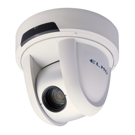
- Page 1 PAN • TILT • ZOOM COLOR CAMERA PTC - 400C INSTRUCTION MANUAL Please read this instruction manual carefully before using this PTC-400C and keep it for future reference.
-
Page 2: Important Safety Instructions
IMPORTANT SAFETY INSTRUCTIONS 1. Read these instructions. 2. Keep these instructions. 3. Heed all warnings. 4. Follow all instructions. 5. Do not use this apparatus outdoors. 6. Do not use this apparatus near water. 7. Clean only with dry cloth. 8. - Page 3 CAUTION RISK OF ELECTRIC SHOCK DO NOT OPEN CAUTION : TO REDUCE THE RISK OF ELECTRIC SHOCK. DO NOT REMOVE COVER (OR BACK). NO USER SERVICEABLE PARTS INSIDE. REFER SERVICING TO QUALIFIED SERVICE PERSONNEL. The lightning flash with arrowhead symbol, within an equilateral triangle, is intended to alert the user to the presence of uninsulated "dangerous voltage"...
-
Page 4: Handling Precautions
HANDLING PRECAUTIONS This Camera has no power switch. When checking and maintaining this Camera, be sure to turn OFF the power supply to the main unit beforehand. This Camera is designed only for use indoors. Do not use this Camera out of doors. -
Page 5: Table Of Contents
CONTENTS IMPORTANT SAFETY INSTRUCTIONS ...1 HANDLING PRECAUTIONS ...3 1. PART NAMES AND FUNCTIONS...5 2. WIRELESS REMOTE CONTROLLER ... 7 3. SETTING UP ... 9 4. OPERATION PROCEDURES ... 14 [1] Power supply to the Camera ... 14 [2] Turning ON/OFF of the Camera power ... 14 [3] Operating PAN/TILT ... -
Page 6: Part Names And Functions
1. PART NAMES AND FUNCTIONS Main unit ALARM IN-OUT TERMINAL (6P connector (Black)) RS-485 TERMINAL (5P connector (White)) COMPOSITE CABLE INFRARED SENSOR LENS CAMERA HEAD DC IN VIDEO OUT TERMINAL (BNC jack) BASE ORNAMENTAL RING - 5 -... -
Page 7: Wireless Remote Controller
Wireless Remote Controller PRESET NUMBER NORMAL AUTO TELE MENU CURSOR PAN/TILT Note: The “ ” button is not used for normal operation. Button Name POWER To turn ON/OFF the Camera power. PRESET To register the preset position. To set the ID No. when multiple Cameras are used. NUMBER To set the preset position and the ID No. -
Page 8: Wireless Remote Controller
2. WIRELESS REMOTE CONTROLLER Point the infrared emitter of the wireless remote controller to the infrared sensor located on the front of the Camera main unit, and press the button of the intended operation. For the receivable renge, refer to the below figures. Receivable range Distance : Within approx. -
Page 9: When Multiple Cameras Are Operated Through The Wireless Remote Controller
Note: The supplied batteries supplied with the Camera are only for use in initially confirming the operation of the Camera. It is not guaranteed that these batteries will work effectively for the indicated period. When multiple Cameras are operated through the wireless remote controller Refer to "5. -
Page 10: Setting Up
3. SETTING UP [1] Installation Note: When carrying the Camera, be sure to hold the base. Note: Do not turn the Camera head in the PAN-TILT direction by hand, or the Camera head could be broken. (1) Mounting the Fixing Plate 1.Make mounting holes and a cord hole in the place (ceiling) to which this Camera is installed. - Page 11 WARNING:Fasten the fixing screws of the fixing plate firmly, or the Camera could fall, causing injury. (2) Mounting the Camera to the Fixing Plate 1.Match the [ ] mark on the fixing plate with the [ main unit, set the tabs (3 locations) of the back face of the main unit in the mating cuts (3 locations) of the fixing plate, and turn the main unit clockwise by 25°...
- Page 12 (3) Mounting the Safety Wires 1.Loop up one end of the Safety Wires through the respective safety wire looping holes made on the Ceiling Plate, and then loop up the other end of the same around the beams or anything that is used to mount ceiling tile channel for structure safety. SAFETY WIRE LOOPING HOLE SAFETY WIRE (not supplied)
-
Page 13: Drawing The Composite Cable From The Camera Back Face
2.Lock the Camera and the fixing plate with the set screws (supplied). [2] Drawing the Composite Cable from the Camera Back Face (1) Cut off the blank cover from the back face of the Camera base with pliers or the like, and draw the composite cable from the back face of the Camera. -
Page 14: Video Cable
Connection of the Camera VIDEO OUT VIDEO CABLE (commercial item, BNC, co-axial) DC IN DC 12V (DC11V-16V) To MONITOR VIDEO IN Camera main unit RS-485 terminal (5P connector (white)) Pin No. Terminal Name Cord Color Brown DATA (+) IN DATA (-) IN Orange DATA (+) OUT Yellow... -
Page 15: Operation Procedures
4. OPERATION PROCEDURES [1] Power supply to the Camera The Camera has no POWER switch. The power supply to the Camera is turned ON when 12VDC is inputted to the DC IN terminal. When power is supplied to the Camera, the Camera turns to the right and then to the center automatically (viewed from the front), returning the Camera position to the position set in advance. -
Page 16: Operating Pan/Tilt
[3] Operating PAN/TILT • When HOME button is pressed, the Camera turns to the front (and the lens moves to the WIDE end) according to the factory settings. The home position can be set freely with the preset No. “0.” (Press button.) After setting, when position is loaded. - Page 17 (2) Focus operation • When AUTO button of FOCUS is pressed, the FULL AUTO FOCUS status is established. However, focusing may be difficult for such objects as listed below. Objects with no contrast between light and shade, such as white walls and night views Objects reflecting an intensive light Objects moving fast Objects with many horizontal stripes, such as...
-
Page 18: Preset Operation
[5] Preset operation The Camera head direction, the zoom position, the focus status and the brightness status can be registered. In addition to these items, when [MAIN CONTROL] – [CAMERA2 PRESET] is set to [ON] in the OSD menu, the [CAMERA2] settings can also be registered together (Refer to P. -
Page 19: External Unit Control
[6] External unit control To make AUX button functional, set [ALARM] – [ALARM OUT2] to [ON] in the OSD menu beforehand. When AUX button is pressed, the external unit connected to the ALARM OUT terminal <2> is turned ON. To turn it OFF, press AUX button again. -
Page 20: The Id Number (Remote Id) Setting
5. THE ID NUMBER (REMOTE ID) SETTING When multiple Cameras are laid out adjacently and operated via the wireless remote controller, the Cameras receiving the infrared rays operates in unison in the same way. When each Camera is allocated with a different ID No., the Camera can be operated selectively when its ID No. -
Page 21: Setting In The Osd (On-Screen Display) Menu
6. SETTING IN THE OSD (ON-SCREEN DISPLAY) MENU OSD menu [ 1 ] MAIN CONTROL Name To turn ON/OFF the character display in the bottom of TITLE the screen. SELECT To select the title [CAMERA/PRESET] to be character- displayed (enabled only when the above [TITLE] is ON). [PRESET]: Preset position names 1 –... -
Page 22: Auto Return
[ 1 ] MAIN CONTROL Name To turn ON/OFF the settings of the RS-485 terminating RS-485 END resistance contained in the Camera main unit. (For the telecommunication equipment to be connected to the RS-485 interface, a terminating resistance should be attached to both ends of the equipment having the longest route to prevent signal damping.) REMOTE ID To set the ID No. - Page 23 [ 2 ] CAMERA1 Name To select the high-speed shutter speed [OFF (1/60s), HS-SHUTTER 1/100s, 1/250s, 1/500s, 1/1000s, 1/2000s, 1/4000s, 1/10000s, 1/20000s, 1/50000s]. When [LS-SHUTTER] is [ON], the shutter speed can be selected from [1/60sm 1/100s]. If the shimmer of fluorescent lamp is annoying when the shutter speed is set to [OFF (1/60s), set the shutter speed to [1/100s], and the shimmer will be eased.
-
Page 24: Blc Mode
[ 3 ] CAMERA2 Name To set the backlight compensation function to [ON/OFF]. When there is an intensive light in the background, this function prevents the object from becoming dark. BLC MODE To select the Backlight Compensation Setting mode [AREA/HIST]. About the Backlight Compensation Setting mode To select the image area of the object that needs an AREA... - Page 25 [ 3 ] CAMERA2 Name INDOOR This function is selected when the Camera is used indoors. The color temperature is assumed to be 3200K. OUTDOOR This function is selected when the Camera is used outdoors. The color temperature is assumed to be 6300K.
- Page 26 [ 4 ] MASKING Name LOCATION To set the mask position, display the [LOCATION] Set window, move the position by using buttons, and then press When the cursor is moved to [SAVE] and SAVE button is pressed, the mask data (position, size) is saved and enabled.
-
Page 27: Motor Speed
[ 6 ] PAN TILT Name MOTOR SPEED To select the motor speed setting [AUTO/MANUAL] for the PAN-TILT operation. When [AUTO] is selected, the operation speed varies automatically according to the zoom position. When [MANUAL] is selected, the operation speed can be selected freely. - Page 28 [ 6 ] PAN TILT Name FLIP ANGLE When the rotation angle exceeds 90˚(the Camera is facing beneath), the image reverses upside down. For example, the ceiling comes to the bottom of the image. In this case, this Camera automatically reverses the image vertically or horizontally.
-
Page 29: Setting Of Alarm In-Out
7. SETTING OF ALARM IN-OUT [1] Alarm Input When each of the ALARM IN terminals <1> and <2> are short-circuited to the GND terminal, the Signal IN mode is established, and the Camera moves to the preset position set in the OSD menu beforehand. (1) Setting of the preset position for the ALARM IN terminals <1>, <2>... -
Page 30: Setting Of Rs-485
8. SETTING OF RS-485 By wiring and connecting the RS-485 terminal of the 5P connector (white) with the RS-485 control, this Camera can be controlled. By setting the ID address for the RS-485 communication in each Camera, up to 223 Cameras can be controlled by a single PC or controller. -
Page 31: Setting Of Various Modes
9. SETTING OF VARIOUS MODES [1] Initializing the settings When the 4P DIP switch No. 2 located on the bottom of the main unit is set to [ON] and the Camera power is turned ON, the PAN-TILT settings, the lens settings, the preset settings, and the Camera settings made in the OSD menu are reset to the factory settings. -
Page 32: Troubleshooting Hints
10. TROUBLESHOOTING HINTS Symptom No image or Is the Camera main unit connected correctly with dark image on the monitor with the video cable? Isn’t the the monitor MONITOR IN terminal of the monitor wrong? Is the DC IN cable connected correctly? Isn’t the DC IN cable or the video cable damaged? Isn’t there any disconnection or incomplete contact? - Page 33 Symptom No operation via Isn’t wrong ID number set? wireless remote Check the remaining battery power of the wireless controller remote controller. If the sunlight or the fluorescent lamp light of the inverter enters the infrared sensor, the signal from the wireless remote controller could not be sensed normally.
-
Page 34: Specifications
11. SPECIFICATIONS General Item Power source DC12V (DC11V-16V) Current consumption MAX. 1A Outside dimensions Diameter 139mm (5.74in.), Height 121mm (4.76in.) (Projections and fitting plate not included) Weight / mass 1.98lb (Fitting plate included) Television system NTSC system Video signal output terminal Composite video External control terminal RS-485... - Page 35 Camera Item Image pickup element Effective picture element Total picture element Minimum illumination Digital zoom Backlight compensation White balance Sync. system Resolution S/N ratio DAY/NIGHT function Masking function Image flip (vertical, horizontal) function AGC gain adjustment Detail compensation level adjustment High-speed shutter Low-speed shutter (Electronic sensitivity up)
-
Page 36: Supplied Accessories
12. SUPPLIED ACCESSORIES Name Wireless remote controller (RC-PTY) Battery size AAA RS-485, Relay cable (5P connector color: White) ALARM IN-OUT, Relay cable (6P connector color: Black) Ceiling plate Main unit set screw M3 × 5 Fixing plate (for under the roof) Fixing screw M4 ×... -
Page 37: Options
13. OPTIONS Name Clear dome cover PTC40CL Smoke dome cover PTC40SM Note: The specifications are subject to change without notice. is a trademark of ELMO CO., LTD. - 36 -... - Page 38 - 37 -...
- Page 39 - 38 -...
- Page 40 6-14, Meizen-cho, Mizuho-ku, Nagoya, 467-8567, Japan OVERSEAS SUBSIDIARY COMPANIES U.S.A ELMO USA CORP. 1478 Old Country Road, Plainview, NY 11803-5034 Tel:(516)501-1400 E-mail:elmo@elmousa.com Web : http://www.elmousa.com Canada ELMO CANADA CORP.
Need help?
Do you have a question about the PTC-400C and is the answer not in the manual?
Questions and answers