Table of Contents
Advertisement
WARNING: This appliance
is equipped for (Natural and
Propane) gas. Field conversion
is not permitted other than
between natural or propane
gases.
CAUTION - FOR YOUR SAFETY
WARNING: IF THE INFORMATION IN THIS MANUAL IS NOT FOLLOWED
EXACTLY, A FIRE OR EXPLOSION MAY RESULT CAUSING PROPERTY
DAMAGE, PERSONAL INJURY OR LOSS OF LIFE.
- Do not store or use gasoline or other flammable vapors and Iiquids in vicinity of
this or any other appliance.
WHAT TO DO IF YOU SMELL GAS
• Do not try to light any appliance.
• Do not touch any electrical switch; do not use any phone in your building.
• Immediately call your gas supplier from a neighbor's phone. Follow the gas
supplier's instructions.
• If you cannot reach your gas supplier, call the fire department.
- Installation and service must be performed by a qualified installer, service agency
or the gas supplier.
This is an unvented gas-fired heater. It uses air (oxygen) from the room in which it is
installed. Provisions for adequate combustion and ventilation air must be provided.
Refer to Air For Combustion and Ventilation section on page 8 of this manual.
CONSUMER: Retain this manual for future reference.
This appliance may be installed in an aftermarket, permanently located manufactured (mobile)
home, where not prohibited by local codes. This appliance is only for use with propane or
natural gas. This appliance is equipped with a simple means to switch between propane and
natural gas. Field conversion by any other means including the use of a kit is not permitted.
The Installation instructions for an appliance for installation on combustible flooring
shall specify that when the appliance is installed directly on carpeting, tile or other
combustible material, other than wood flooring, the appliance shall be installed on a
metal or wood panel extending the full width and depth of the appliance.
Questions, problems, missing parts? Before returning to your retailer, call our customer
service department at 1-877-447-4768, 8:30 a.m. – 4:30 p.m., CST, Monday – Friday or
email us at customerservice@ghpgroupinc.com.
INSTALLER: Leave this manual with the appliance.
NG
Dual Fuel
1
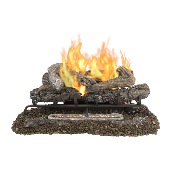
VENT-FREE
GAS LOG SET
MODEL # VFL2-VO24DR
VFL2-RO24DR
VFL2-VO30DR
VFL2-RO30DR
VFL2-MO24DR
VFL2-MO30DR
Patent Pending Dual
Fuel System
LP
C
C
US
ANS Z21.11.2 2013
80-10-443 - 2018-06-01
US
Advertisement
Table of Contents

Related Manuals for pleasant hearth VFL2-VO30DR


Summary of Contents for pleasant hearth VFL2-VO30DR
- Page 1 VENT-FREE GAS LOG SET MODEL # VFL2-VO24DR VFL2-RO24DR VFL2-VO30DR VFL2-RO30DR VFL2-MO24DR VFL2-MO30DR WARNING: This appliance is equipped for (Natural and Patent Pending Dual Propane) gas. Field conversion Fuel System is not permitted other than between natural or propane gases. CAUTION - FOR YOUR SAFETY Dual Fuel ANS Z21.11.2 2013...
-
Page 2: Operation
OPERATION FOR YOUR SAFETY READ BEFORE LIGHTING WARNING: If you do not follow these instructions exactly, a fire or explosion may result causing property damage, personal injury or loss of life. A. This appliance has a pilot which must be lighted by the electronic ignitor. When lighting the pilot, follow these instructions exactly. -
Page 3: Lighting Instructions
OPERATION LIGHTING INSTRUCTIONS 1. STOP! Read the safety information as noted above. LEARN 2. Set receiver switch to “ON” position (See Fig. 26). 3. Turn control knob clockwise to the “OFF” position (See Fig. 26). 4. Wait five (5) minutes to clear out any gas. Then smell for gas, including near the floor. -
Page 4: Remote Control Operation
REMOTE CONTROL OPERATION MULIT-FUNCTION WIRELESS REMOTE CONTROL SYSTEM FOR OPERATING A LATCHING SOLENOID VALVE, MANUALLY OR WITH A THERMOSTAT FUCTION IF YOU CANNOT READ OR UNDERSTAND THESE INSTALLATION INSTRUCTIONS DO NOT ATTEMPT TO INSTALL OR OPERATE INTRODUCTION This remote control system was developed to provide a safe, reliable, and user-friendly remote control system for gas heating appliances. -
Page 5: Manual Function
REMOTE CONTROL OPERATION LCD - Liquid Crystal Display DISPLAY Indicates CURRENT room temperature . F OR Indicates degrees Fahrenheit or Celsius. FLAME Indicates burner/valve in operation. ROOM Indicates remote is in THERMO operation. TEMP Appears during manual operation. ROOM TEMP Appears during time the of setting the desired temperature in the thermo operation. - Page 6 REMOTE CONTROL OPERATION release the SET key. The LCD screen will display the set temperature for 3 seconds and the LCD screen will flash the set temperature for 3 seconds, then the LCD screen will default to display the room temperature.
-
Page 7: Installation Instructions
REMOTE CONTROL OPERATION FUNCTIONS: With the slide switch in the REMOTE position, the system will only operate • Remote Receiver if the remote receiver receives commands from the transmitter. Wire terminals Upon initial use or after an extended period of no use, the ON button may •... -
Page 8: General Information
REMOTE CONTROL OPERATION NOTE: Up to 6.3 VDC of power is provided at the receiver terminal. GENERAL INFORMATION COMMUNICATION – SAFETY – TRANSMITTER – (C/S – TX) This remote control has a COMMUNICATION –SAFETY function built into its software. It provides an extra margin of safety when the TRANSMITTER is out of the normal 20-foot operating range of the receiver. -
Page 9: Specifications
REMOTE CONTROL OPERATION TRANSMITTER WALL CLIP The transmitter can be hung on a wall using the clip provided. If the clip is installed on a solid wood wall, drill 1/8" pilot holes and install with the screws WALL CLIP SLOT provided. -
Page 10: Inspecting Burners
OPERATION INSPECTING BURNERS Check pilot flame pattern and burner flame patterns often. PILOT FLAME PATTERN Figure 29 shows a correct pilot flame pattern. Figure 30 shows an incorrect pilot flame pattern. The incorrect pilot flame is not touching the thermocouple. This will cause the thermocouple to cool. When the thermocouple cools, the heater will shut down.
Need help?
Do you have a question about the VFL2-VO30DR and is the answer not in the manual?
Questions and answers