Table of Contents
Advertisement
Available languages
Available languages
WARNING:
This appliance is
equipped for (Natural
and Propane) gas.
Field conversion is
not permitted other
than between natural
or propane gases.
CAUTION - FOR YOUR SAFETY
WARNING: IF THE INFORMATION IN THIS MANUAL IS NOT FOLLOWED
EXACTLY, A FIRE OR EXPLOSION MAY RESULT CAUSING PROPERTY
DAMAGE, PERSONAL INJURY OR LOSS OF LIFE.
- Do not store or use gasoline or other flammable vapors and Iiquids in vicinity of this
or any other appliance.
WHAT TO DO IF YOU SMELL GAS
• Do not try to light any appliance.
• Do not touch any electrical switch; do not use any phone in your building.
• Immediately call your gas supplier from a neighbor's phone. Follow the gas supplier's
instructions.
• If you cannot reach your gas supplier, call the fire department.
- Installation and service must be performed by a qualified installer, service agency or
the gas supplier.
This is an unvented gas-fired heater. It uses air (oxygen) from the room in which it is
installed. Provisions for adequate combustion and ventilation air must be provided.
Refer to Air For Combustion and Ventilation section on page 8-10 of this manual.
This appliance may be installed in an aftermarket, permanently located manufactured
(mobile) home, where not prohibited by local codes. This appliance is only for use with
propane or natural gas. This appliance is equipped with a simple means to switch between
propane and natural gas. Field conversion by any other means including the use of a kit is
not permitted.
Questions, problems, missing parts? Before returning to your retailer, call our customer
service department at 1-877-447-4768, 8:30 a.m. – 4:30 p.m., CST, Monday – Friday or
email us at customerservice@ghpgroupinc.com.
INSTALLER: Leave this manual with the appliance.
CONSUMER: Retain this manual for future reference.
VFS2-PH20DT/ VFS2-L20DT/ VFS2-NT20DT
VFS2-PH30DT/ VFS2-L30DT/ VFS2-NT30DT
1
VENT-FREE GAS
DUAL FUEL HEATER
MODEL #
Patent Pending Dual
Fuel Technology
NG
Dual Fuel
US
ANS Z21.11.2-2016
IMVFSG2L - 2019-2-27
LP
Advertisement
Chapters
Table of Contents

Subscribe to Our Youtube Channel
Related Manuals for pleasant hearth VFS2-NT20DT


Summary of Contents for pleasant hearth VFS2-NT20DT
- Page 1 VENT-FREE GAS DUAL FUEL HEATER MODEL # VFS2-PH20DT/ VFS2-L20DT/ VFS2-NT20DT VFS2-PH30DT/ VFS2-L30DT/ VFS2-NT30DT WARNING: Patent Pending Dual This appliance is Fuel Technology equipped for (Natural and Propane) gas. Field conversion is not permitted other than between natural Dual Fuel or propane gases.
- Page 2 WARNING: Any safety screen or guard removed for servicing an appliance must be replaced prior to operating the heater. WARNING: When the appliance is installed directly on carpeting, tile or other combustible material, other than wood flooring, the appliance shall be installed on a metal or wood panel extending the full width and depth of the appliance.
-
Page 3: Table Of Contents
IMPORTANT: Read all instructions and warnings carefully before starting installation. Failure to follow these instructions may result in possible injury to persons or a fire hazard and will void the warranty. VFS2-L20DT VFS2-L30DT Model VFS2-PH20DT / VFS2-NT20DT VFS2-PH30DT / VFS2-NT30DT 20,000 BTU/Hr 30,000 BTU/Hr Input Rating Minimum Input Rating... -
Page 4: Important Safety Information
IMPORTANT SAFETY INFORMATION WARNING: FIRE, EXPLOSION, AND ASPHYXIATION HAZARD Improper adjustment, alteration, service, maintenance, or installation of this heater or its controls can cause death or serious injury. Read and follow instructions and precautions in User's Information Manual provided with this heater. IMPORTANT: Read this owner’s manual carefully and completely before trying to assemble, operate, or service this heater. - Page 5 SAFETY INFORMATION 1. This appliance is only for use with the type of gas indicated on the rating plate. This appliance is not convertible for use with other gases. 2. Do not place propane/LP supply tank(s) inside any structure. Locate propane/LP supply tank(s) outdoors. 3.
-
Page 6: Product Identification
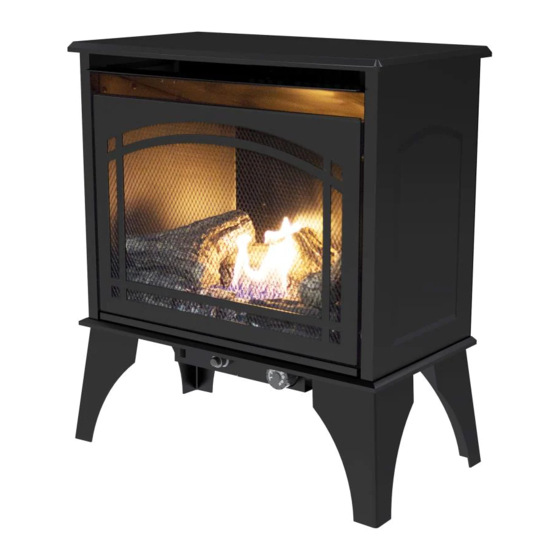
PRODUCT IDENTIFICATION Stove Cabinet Hood Screen Logs Ignitor Control Button Knob Stove Cabinet Hood Screen Logs Control Cover... -
Page 7: Product Features
PRODUCT FEATURES SAFETY PILOT This heater has a pilot with an Oxygen Depletion Sensing (ODS) safety shutoff system. The ODS/pilot shuts off the heater if there is not enough fresh air and cuts off main burner gas in the event of flame out. ELECTRIC PUSH BUTTON IGNITION SYSTEM This heater is equipped with an electronic push button control system. -
Page 8: Preparing For Installation
PREPARING FOR INSTALLATION AIR FOR COMBUSTION AND VENTILATION WARNING: This heater shall not be installed in a room or space unless the required volume of indoor combustion air is provided by the method described in the Nation Fuel Gas Code, ANS Z223.1/NFPA 54, the International Fuel Gas Code, or applicable local codes. - Page 9 PREPARING FOR INSTALLATION DETERMINING FRESH-AIR FLOW FOR HEATER LOCATION Determining if You Have a Confined or Unconfined Space Use this worksheet to determine if you have a confined or unconfined space. Space: Includes the room in which you will install heater plus any adjoining rooms with doorless passageways or ventilation grills between the rooms.
- Page 10 PREPARING FOR INSTALLATION Ventilation Air From Inside Building This fresh air would come from adjoining unconfined space. When ventilating to an adjoining unconfined space, you must provide two permanent openings: one within 12 in. of the wall connecting the two spaces (see options 1 and 2, Fig.
-
Page 11: Installation
INSTALLATION NOTICE: This heater is intended for use as supplemental heat. Use this heater along with your primary heating system. Do not install this heater as your primary heat source. If you have a central heating system, you may run system’s circulating blower while using heater. This will help circulate the heat throughout the house. - Page 12 INSTALLATION Heater CLEARANCES CAUTION: If you install the heater in a home garage • heater pilot and burner must be at least 18" above floor. • locate heater where moving vehicle will not hit it. For convenience and efficiency, install heater •...
- Page 13 INSTALLATION WARNING: The optional blower is equipped with a three-prong (grounding) plug for your protection against shock hazard and must be plugged directly into a properly grounded three-prong receptacle. Heater must be disconnected from gas supply before installing fan accessory. Contact a qualified service person to do this.
- Page 14 INSTALLATION BATTERY INSTALLATION Step 1 – Locate the Push Button Ignitor by lowering the cover on the bottom of the stove. (Fig. 1) Step 2 – Unscrew the cap on the Push Button Ignitor with your fingers by turning it counterclockwise. (Fig.
- Page 15 INSTALLATION GAS SELECTION INSTRUCTIONS WARNING: This appliance can be used with propane or natural gas. It is shipped from the factory adjusted for use with propane. CAUTION: The knob to the gas selection means shall not be accessed or adjusted while the ap- pliance is in operation.
- Page 16 INSTALLATION CONNECTING TO GAS SUPPLY WARNING: A qualified service technician must connect heater to gas supply. Follow all local codes. CAUTION: Never connect heater directly to the gas supply. This heater requires an external regulator (not supplied). The external regulator between the gas supply and heater must be in- stalled.
- Page 17 INSTALLATION CAUTION: Use pipe joint sealant that is resistant to gas (PROPANE or NG). We recommend that you install a sediment trap in a supply line as shown in Fig. 10. Locate sediment trap where it is within reach for cleaning and not likely to freeze. Install in the piping system between fuel supply and heater.
- Page 18 ASSEMBLING LOGS WARNING: Failure to position the parts in accordance with these diagrams or failure to use only parts specifically approved with this heater may result in property damage or personal injury. CAUTION: After installation and periodically thereafter, check to ensure that no yellow flame comes in contact with any log.
- Page 19 INSTALLATION CHECKING GAS CONNECTIONS WARNING: Test all gas piping and connections for leaks after installing or servicing. Correct all leaks immediately. WARNING: Never use an open flame to check for a leak. Apply a mixture of liquid soap and water to all joints.
-
Page 20: Operation
OPERATION FOR YOUR SAFETY READ BEFORE LIGHTING WARNING: If you do not follow these instructions exactly, a fire or explosion may result causing property damage, personal injury or loss of life. A. This appliance has a pilot which must be lighted by the electronic ignitor. When lighting the pilot, follow these instructions exactly. - Page 21 OPERATION TO TURN OFF GAS TO APPLIANCE 1. (Select units) Open the lower access panel located under the heater screen. 2. Turn control knob clockwise to the “OFF” position. 3. (Select units) Close lower access panel. INSPECTING BURNERS Check pilot flame pattern and burner flame patterns often. PILOT FLAME PATTERN Figure 20 shows a correct pilot flame pattern.
-
Page 22: Care And Maintenance
CARE AND MAINTENANCE BURNER FLAME PATTERN Figure 22 shows a correct burner flame pattern. Figure 23 shows an incorrect burner flame pattern. The incorrect burner flame pattern shows sporadic, irregular flame tipping. The flame should not be dark or have an orange/reddish tinge. Note: When using the heater the first time, the flame will be orange for approximately one hour until the log cures. - Page 23 CARE AND MAINTENANCE 1. Shut off unit including pilot. Allow unit to cool for at least 30 minutes. 2. Inspect burner, pilot and primary air inlet holes on orifice holder for dust and dirt (See Fig. 24). 3. Blow air through the ports/slots and holes in the burner. 4.
-
Page 24: Troubleshooting
TROUBLESHOOTING WARNING: If you smell gas: • Shut off gas supply. • Do not try to light any appliance. • Do not touch any electrical switch; do not use any phone in your building. • Immediately call your gas supplier from a neighbor’s phone. Follow the gas supplier’s instructions. •... - Page 25 TROUBLESHOOTING PROBLEM POSSIBLE CAUSE CORRECTIVE ACTION 1. Control knob is not fully ODS/pilot lights 1. Press in control knob fully. pressed in. but flame goes out 2. Control knob is not pressed when control knob is 2. After ODS/pilot lights, keep control in long enough.
- Page 26 TROUBLESHOOTING PROBLEM POSSIBLE CAUSE CORRECTIVE ACTION White powder resi- 1. When heated, the vapors 1. Turn heater off when using furniture due forming within from furniture polish, wax, polish, wax, carpet cleaner or similar burner box or on carpet cleaners, etc., turn products.
-
Page 27: Replacement Parts
REPLACEMENT PARTS For replacement parts, call our Technical Service Department at 1-877-447-4768, 8:30 a.m. –4:30 p.m., CST, Monday – Friday. ITEM No. Description Part Number VFS2-L20DT VFS2-L30DT VFS2-PH20DT VFS2-PH30DT VFS2-NT20DT VFS2-NT30DT Screen Assembly EXP-A3007 EXP-A3005A Legs EXP-3039 EXP-3004ipt Control Cover EXP-3044... -
Page 28: Accessories
For replacement parts, call our Technical Service Department at 1-877-447-4768, 8:30 a.m. –4:30 p.m., CST, Monday – Friday. PART NUMBER ITEM VFS2-L20DT VFS2-L30DT DESCRIPTION VFS2-PH20DT VFS2-PH30DT VFS2-NT20DT VFS2-NT30DT Log Set (complete) 700-S1018 700-M1018 1 - 1 Log 1 700-S1018-01 700-M1018-01... - Page 30 This limited warranty is extended to the original retail purchaser of this heater and warrants against any years years...
- Page 31 GHP Group, Inc. 6440 W Howard St Niles, IL 60714-3302 Tel: (877) 447-4768 www.ghpgroupinc.com GHP Group, Inc. 6440 W Howard St Niles, IL 60714-3302...
- Page 32 CHIMENEA DE COMBUSTIBLE DUAL A GAS DE TIRO NATURAL NÚM. DE MODELO VFS2-PH20DT/VFS2-L20DT/VFS2-NT20DT ADVERTENCIA: VFS2-PH30DT/VFS2-L30DT /VFS2-NT30DT Este dispositivo está Pendiente de patente equipado para gas istema de Combustible Dual (natural y propano). La conversión de campo no está permitida a menos...
- Page 33 ADVERTENCIA: Cualquier pantalla o protección de seguridad retirada para dar servicio a un aparato debe volverse a colocar antes de la operación del calefactor. ADVERTENCIA: Si este aparato se va a instalar directamente sobre alfombra, baldosa u otro material combustible, que no sea piso de madera, el aparato debe ser instalado sobre un panel metálico o de madera que se extienda en la anchura y profundidad completas del aparato.
- Page 34 No seguir estas instrucciones puede resultar en posibles lesiones a las personas o peligro de incendio y anulará la garantía. VFS2-L20DT VFS2-L30DT Modelo VFS2-PH20DT VFS2-PH30DT VFS2-NT20DT VFS2-NT20DT 20,000 BTU/Hr 30,000 BTU/Hr Capacidad nominal de entrada Capacidad mínima de entrada 16,000 BTU/Hr...
-
Page 35: Información De Seguridad Importante
INFORMACIÓN DE SEGURIDAD IMPORTANTE ADVERTENCIA: PELIGRO DE INCENDIO, EXPLOSIÓN Y ASFIXIA La alteración, el ajuste, servicio, mantenimiento o la instalación inadecuada de este calentador o sus controles pueden causar lesiones graves o incluso la muerte. Lea y siga las instrucciones y precauciones en el Manual de información del usuario proporcionado en este calentador. - Page 36 INFORMACIÓN DE SEGURIDAD 1. Este aparato es solo para ser usado con el tipo de gas indicado en la placa de características. Este aparato no es convertible para uso con otros gases. 2. No coloque el(los) tanque(s) de suministro de propano/PL dentro de ninguna estructura. Coloque el(los) tanque(s) de suministro de propano/PL en exteriores.
-
Page 37: Identificación Del Producto
IDENTIFICACIÓN DEL PRODUCTO Gabinete de Extractor la estufa Pantalla Leños Botón de Perilla encendedor de control Gabinete de la estufa Extractor Pantalla Leños Cubierta de control... -
Page 38: Características Del Producto
CARACTERÍSTICAS DEL PRODUCTO PILOTO DE SEGURIDAD Este calefactor tiene un piloto con un sistema de apagado de seguridad de Detección de disminución de oxígeno (ODS). El ODS/piloto apaga el calefactor si no hay suficiente aire fresco y corta el gas del quemador principal en el caso de que la llama se apague. -
Page 39: Preparación Para La Instalación
PREPARACIÓN PARA LA INSTALACIÓN AIRE PARA LA COMBUSTIÓN Y VENTILACIÓN ADVERTENCIA: Este calefactor no deberá ser instalado en una habitación o espacio a menos que el volumen requerido de aire de combustión de interiores sea proporcionado por el método descrito en el Código Nacional de Gas Combustible, ANS Z223.1/NFPA 54, el Código Internacional de Gas Combustible, o códigos locales aplicables. - Page 40 PREPARACIÓN PARA LA INSTALACIÓN DETERMINACIÓN DEL FLUJO DE AIRE FRESCO A LA UBICACIÓN DEL CALEFACTOR Determinación de si tiene un espacio confinado o no confinado Use esta hoja de cálculo para determinar si tiene un espacio confinado o no confinado. Espacio: Incluye la habitación en la cual instalará...
- Page 41 PREPARACIÓN PARA LA INSTALACIÓN Aire de ventilación desde el interior del edificio Este aire fresco vendría del espacio no confinado contiguo. Cuando se ventila a un espacio no confinado contiguo, debe proporcionar dos aberturas permanentes: una dentro de 12 pulg. de la pared que conecta los dos espacios (ver opciones 1 y 2, Fig.
-
Page 42: Instalación
INSTALACIÓN AVISO: Este calefactor está diseñado para ser usado como calor complementario. Use este calefactor junto con su sistema de calefacción primario. No instale este calefactor como su fuente primaria de calor. Si tiene un sistema de calefacción central, puede poner a funcionar un soplador de circulación del sistema mientras usa el calefactor. - Page 43 INSTALACIÓN ESPACIOS LIBRES del calefactor PRECAUCIÓN: Si instala el calefactor en la cochera de su casa • el piloto y el quemador del calefactor deben estar al menos a 18 pulg. sobre el piso. • coloque el calefactor donde vehículos en movimiento no lo golpeen. Por conveniencia y eficiencia, instale el calefactor: •...
- Page 44 INSTALACIÓN Panel preperforado Retire antes de INSTALACIÓN DEL SOPLADOR (OPCIONAL) Parte trasera la instalación del soplador de la estufa El soplador se instalará en la parte trasera de Junta la estufa, en el protector térmico trasero. Alinee el soplador y los agujeros de montaje de la Soplador junta con los del protector térmico trasero.
- Page 45 INSTALACIÓN Instrucciones Para La Instalación De Batería Paso 1 - Localize el encendedor electrónica de botón de presión mediante la reducción de la cubierta en la parte inferior de la estufa. (Figura 1) Paso 2 - Desenroscar el casquillo en el encendedor Electrónica de botón de presión con sus dedos girándola hacia la izquierda.
- Page 46 INSTALACIÓN INSTRUCCIONES DE SELECCIÓN DEL GAS ADVERTENCIA: Este aparato puede ser usado con propano o gas natural. Es enviado de la fábrica ajustado para ser usado con propano. PRECAUCIÓN: No se debe acceder a ni ajustar la perilla para los medios de selección del gas mientras el aparato esté...
- Page 47 INSTALACIÓN INSTALACIÓN CONEXIÓN AL SUMINISTRO DE GAS CONEXIÓN AL SUMINISTRO DE GAS ADVERTENCIA: Un técnico de servicio calificado debe conectar el calefactor al suministro de gas. Siga todos los códigos locales. ADVERTENCIA: Un técnico de servicio calificado debe conectar el calefactor al suministro de gas.
- Page 48 INSTALACIÓN PRECAUCIÓN: Use sellador de juntas de tubo que sea resistente al gas (PROPANO O GN). Recomendamos una trampa de sedimentos en una línea de suministro como se muestra en la Fig. 10. Ubique la trampa de sedimentos donde esté al alcance para limpieza y que no existan probabilidades de que se congele.
- Page 49 ENSAMBLAJE DE LOS LEÑOS ADVERTENCIA: No colocar las piezas de acuerdo con estos diagramas o no usar solamente piezas específicamente aprobadas con este calefactor puede resultar en daños a la propiadad o lesiones personales. PRECAUCIÓN: Después de la instalación y a partir de alli periódicamente, revise para asegurarse de que ninguna llama amarilla entre en contacto con los leños.
- Page 50 INSTALACIÓN REVISIÓN DE LAS CONEXIONES DE GAS ADVERTENCIA: Pruebe toda la tubería y conexiones de gas en contra de fugas después de la instalación y el servicio. Corrija todas las fugas de inmediato. ADVERTENCIA: Nunca use una llama abierta para revisar en busca de fugas. Aplique una mezcla de jabón líquido y agua en todas las juntas.
-
Page 51: Operación
OPERACIÓN PARA SU SEGURIDAD LEA ANTES DEL ENCENDIDO ADVERTENCIA: Si no sigue estas instrucciones exactamente, puede resultar un incendio o explosión ocasionando daños a la propiedad, lesiones personales o la muerte. A. Este aparato tiene una piloto que debe ser encendido por el encendedor electrónico. Cuando encienda el piloto, siga estas instrucciones exactamente. - Page 52 OPERACIÓN PARA APAGAR EL GAS AL APARATO 1. (Modelos seleccionados) Abra el panel de acceso inferior ubicado debajo de la pantalla del calefactor. 2. Gire la perilla de control hacia la derecha a la posición “OFF”. 3. (Modelos seleccionados) Cierre el panel de acceso inferior. INSPECCIÓN DE LOS QUEMADORES Revise con frecuencia el patrón de la llama del piloto y los patrones de la llama del quemador.
-
Page 53: Cuidado Y Mantenimiento
CUIDADO Y MANTENIMIENTO PATRÓN DE LA LLAMA DEL QUEMADOR La Figura 22 muestra un patrón correcto de la llama del quemador. La Figura 23 muestra un patrón incorrecto de la llama del quemador. El patrón incorrecto de la llama del quemador muestra puntas de llama esporádicas e irregulares. - Page 54 CUIDADO Y MANTENIMIENTO 1. Apague la unidad incluyendo el piloto. Deje que la unidad se enfríe durante 30 minutos. 2. Inspeccione el quemador, el piloto y los agujeros de entrada de aire primario en el porta orificio en busca de polvo y suciedad (Ver Fig.
-
Page 55: Resolución De Fallas
RESOLUCIÓN DE FALLAS ADVERTENCIA: Si huele gas: • Apague el suministro de gas • No trate de encender ningún aparato. • No toque ningún interruptor eléctrico; no use ningún teléfono en su edificio. • LLame de inmediato a su proveedor de gas del teléfono de un vecino. Siga las instrucciones del proveedor de gas. •... - Page 56 RESOLUCIÓN DE FALLAS PROBLEMA CAUSA POSIBLE ACCIÓN CORRECTIVA 1. La perilla de control no está El ODS/piloto enciende 1. Oprima por completo la perilla de control completamente presionada. pero la llama se apaga 2. Después que enciendan el ODS/piloto, 2. La perilla de control no está cuando la perilla de mantenga la perilla de oprimida durante 30 presionada suficiente tiempo.
- Page 57 RESOLUCIÓN DE FALLAS PROBLEMA CAUSA POSIBLE ACCIÓN CORRECTIVA Residuo de polvo blanco 1. Cuando se calientan, los vapores 1. Apague el calefactor cuando use pulidor de que se forma dentro de del pulidor de muebles, cera, mueble, cera, limpiador de alfombra o productos la caja del quemador o limpiadores de alfombra, ect.
-
Page 58: Piezas De Repuesto
Para piezas de repuesto, llame a nuestro departamento de servicio al cliente al 1-877-447-4768, de lunes a viernes, de 8:30 a.m. a 4:30 p.m., hora estándar del Centro. No. De Artículo Descripción CANT. Numero De Pieza VFS2-L20DT VFS2-L30DT VFS2-PH20DT VFS2-PH30DT VFS2-NT20DT VFS2-NT30DT Ensamblaje EXP-A3007 EXP-A3005A Patas EXP-3039 EXP-3004ipt Perilla de cubierta EXP-3044... -
Page 59: Accesorios
8:30 a.m. a 4:30 p.m., hora estándar del Centro. NUMERO DE PIEZA VFS2-L20DT VFS2-L30DT VFS2-PH20DT VFS2-PH30DT VFS2-NT20DT VFS2-NT20DT ACCESORIOS AVISO: Pueden no estar disponibles todos los accesorios para todos los modelos de calefactor. KIT DE SOPLADOR - PBAR-2427 Para todos los modelos. Proporciona mejor distribución del calor. -
Page 61: Garantía
Garantía Garantía 1. esta garantía, y tampoco el fabricante asumirá LIMITED WARRANTY: El fabricante garantiza que su nuevo producto está libre responsabilidad por lo mismo. Además, el fabricante This limited warranty is extended to the original retail purchaser of this Forced Air/Convection/Radiant Heater and warrants against any de defectos de fabricación y materiales por un periodo 1. - Page 62 REGISTRO DE LA GARANTÍA IMPORTANTE: Le urgimos que llene su tarjeta de registro de la garantía en el plazo de catorce (14) días después de la fecha de compra. También puede registrar su garantía en internet en www.ghpgroupinc.com. Complete el número de serie. Conserve esta porción de la tarjeta para sus registros.
Need help?
Do you have a question about the VFS2-NT20DT and is the answer not in the manual?
Questions and answers