
Related Manuals for Emtron DX-1d


Summary of Contents for Emtron DX-1d
- Page 1 OPERATING MANUAL EMTRON DX-1d HF LINEAR AMPLIFIER April 2003 Emtron DIVISION OF EMONA ELECTRONICS PTY. LTD. 92-94 Wentworth Avenue, Sydney 2010, Australia Tel. +612 92110988 Fax +612 92811508 www.emtron.com.au...
- Page 2 DX-1d, Serial No………… INITIAL SETTINGS FOR PLATE AND LOAD CAPACITORS TEST BAND FACTORY SETTINGS USER SETTING FREQUENCY 50 OHM LOAD ANTENNA PLATE LOAD PLATE LOAD 28.600 MHz 24.900 MHz 21.200 MHz 18.100 MHz 14.200 MHz 7.070 MHz 3.600 MHz 1.800MHz 160m 1.850 MHz...
-
Page 3: Table Of Contents
XCITER ............................12 ARTH AND MAINS CONNECTIONS ) ..........................12 HE POWER CABLE EXPORT VERSION 230V, 220V, 200V, 100V 120V ( )................12 PERATION AT EXPORT VERSION DX-1D DESCRIPTION................................14 RF S ....................................14 ECTION ................................14 AINS TRANSFORMER H. V. P ................................14 OWER UPPLY ................................14 OFT START MODULE ..................................14... - Page 4 12.4 ...............................20 TEMPERATURE CUT 12.5 ...............................21 CURRENT CUT 12.6 ..........................21 BLINKS FAST O PLATE VOLTAGE 12.7 ............................21 PARKS ISCHARGES IN AREA 12.8 ..................................21 12.9 ........................21 REQUENT OVER DRIVE PROTECTION CUT 12.10 ................................21 UBE REPLACEMENT WARRANTY / SERVICE ..............................21 GLOSSARY....................................22 APPENDIX 1: SCHEMATIC DIAGRAMS.........................23 15.1 DX-1 ...............................23...
-
Page 5: General Description
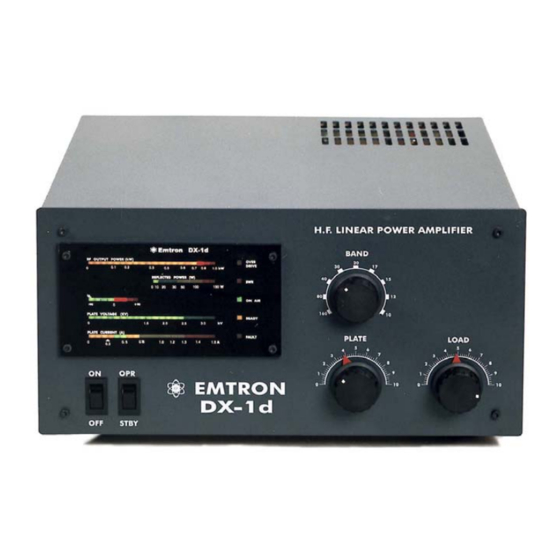
1 GENERAL DESCRIPTION The Emtron DX-1d Linear Amplifier is a 750 watt average output power, for the 160m through 10m amateur bands (9 bands), housed in a desk-top cabinet with self-contained power supply and cooling system. -
Page 6: D - Internal View
1.1 DX-1d – Internal View The main components of a DX-1d amplifier are shown in the picture below. BLOWER ANT. RELAY RF SENSOR SOFT START SAFETY MICORSWITCH RF CHOKE Temperature Sensor HIGH VOLTAGE POWER SUPPLY Tetrode GU84B (4CX800) CONTROL BOARD... -
Page 7: Technical Specifications
OPERATIONAL PROTECTION • Overdrive protection: Should the DX-1d be overdriven, a LED warning indictor will light up when the linearity limit is reached. If the drive is increased further, a 2 second cut off (by-pass) will follow. -
Page 8: Unpacking
WEIGHT: 20kg (44 lb) unpacked 3 UNPACKING The DX-1d is packed in a heavy duty package easily sufficient to protect the amplifier during transportation, even in case of fairly rough handling. The weight of the commercially rated mains transformer does mean, however, that dropping the amplifier would without doubt result in some damage. -
Page 9: Installation Environment
5.1 Power / Earth connections A wing-nut Earth connection is provided at the rear of DX-1d. A good Earth link must be provided here. Connect this first, before making any other connection to the amplifier. Two fuse holders are fitted along with 15A, normal acting fuses. -
Page 10: Front Panel
This jack must be connected to transceiver or exciter relay contacts which are open on RECEIVE and closed on TRANSMIT. In the standard version (DX-1d fitted with a l2V antenna relay), the PTT input presents an open circuit voltage of + l2V with respect to the chassis, with an impedance of about 70 ohm. Therefore, a current of typically 0.17 A must be switched by the transceiver or exciter. - Page 11 READY - single LED, yellow. Turns on at the end of warm-up period, when the mains power to DX-1d is switched on. It turns off for about 2 minutes if the plate current protection is triggered. In this case, the FAULT light also turns on.
-
Page 12: Electrical Connections
Before connecting any power to the amplifier, make a good Earth connection to the screw with wing nut at the rear of DX-1d. Make sure the POWER switch on the front panel is in the OFF position. Then plug the power cable into the power point. - Page 13 LINK 240V: LINK 230V: LINK 220V: LINK 200V: 120V: 100V: Figure 3: TRANSFORMER AC INPUT CONNECTIONS...
-
Page 14: Dx-1D Description
8 DX-1d DESCRIPTION 8.1 RF Section The RF section occupies the right hand side of the DX-1d (looking from the top - front). See picture in 1.1. RF Switch and tuned circuits At the front of the amplifier are two variable capacitors, for plate and load tuning. A 9-position ceramic switch is employed for the 9 operating bands. -
Page 15: Display Board
2 seconds. It ensures a clean signal, making it virtually impossible to overdrive the DX-1d • SWR detector and timer - switches the amplifier to bypass mode for about 3 seconds when high SWR is detected. -
Page 16: Powering Up
Switch now the mains power ON (The power switch to ON position). The "soft start" system will take about 5 seconds to fully turn the power on. SWR light will turn on briefly, then off. Wait for the DX-1d to warm up, until the READY light turns on. -
Page 17: Final Tuning
• Repeat the above steps, while gradually increasing the input drive power, until the overdrive indicator just starts turning on. Now the DX-1d is tuned for operation at full power on that particular operating frequency. NOTES: 1. The maximum power is obtained from a DX-1d when:... -
Page 18: Potential Problems During Tuning
NOTE: Some types of transceivers (e.g. YAESU FTI00MP, FT920 and others) are not compatible with this type of ALC. They require an ALC signal proportional with the output power. DX-1d' s ALC is zero until the drive reaches the over-drive limit, when the negative voltage increases sharply. YAESU operating manual indicates that this type of ALC might not work well with their transceivers, since grid current could be generated by amplifier mis-tuning not related to excessive drive conditions. -
Page 19: Using Your Dx-1D
400 microamperes of grid current. See the Appendix 2 and the Troubleshooting section for oscilloscope displays showing examples of a two tone generator driving the DX-1d in linear mode, and an overdrive situation, when a DX-1d with the overdrive protection disabled is being overdriven by the two-tone generator. -
Page 20: Switching The Power Off
If it is still not working, unplug the power cord from the mains, then remove the fuses from the fuse holders on the rear, panel of DX-1d and check them with an ohmmeter. If a fuse is blown, replace it with a fuse of the same type and try again. -
Page 21: Over-Current Cut-Off
The screen current limiting in DX-1d is so efficient, that the tube is fully protected even in such a situation and test bench DX-1d's have been extensively run with no plate voltage and maximum screen voltage, with no effect on the tube. -
Page 22: Glossary
14 GLOSSARY Alternating Current Automatic Level Control Amplitude Modulation Continuous Wave Direct Current Electronic Bias Switch Frequency Modulation High Frequency Light Emitting Diode Peak Envelope Power Radio Frequency RTTY Radio Tele Type Single Side Band SSTV Slow Scan Tele Vision Standing Wave Ratio Volts, Alternating Current Volts, Direct Current... -
Page 23: Appendix 1: Schematic Diagrams
15 APPENDIX 1: SCHEMATIC DIAGRAMS 15.1 DX-1d Block Diagram POWER SUPPLY DISPLAY MODULE MODULE (See Schematic) & METERS (See Schematic) O’DRIVE FAULT ON AIR H.V. H.V. READY Protec RF / TUBE Protect MODULE -Eg1 (See Schematic) SENSOR CONTROL BOARD MODULE... -
Page 24: Circuit Diagram - High Voltage Power Supply
15.2 Circuit Diagram – HIGH VOLTAGE POWER SUPPLY 470uF/450V 6A100 6A100 1000pF 1000pF 330k 6A100 6A100 1000pF 1000pF 470uF/450V 330k 6A100 6A100 1000pF 1000pF 470uF/450V 330k 6A100 6A100 1000pF 1000pF 470uF/450V 330k 6A100 6A100 1000pF 1000pF 470uF/450V 330k 6A100 6A100 1000pF 1000pF 6A100... -
Page 25: Control Board And Adjustment Points
15.3 Control Board and Adjustment Points SOLDER SIDE VIEW The drawing below show all the connections to the control board and the adjustment points. Unless you know very well what you are doing and you have a reason to do it, do not modify any adjustment! Y/GRN ONLY Y/GRN... -
Page 26: Circuit Diagram - Ac Input And Wiring Diagram - Standard
15.4 Circuit Diagram – AC INPUT AND WIRING DIAGRAM – Standard... -
Page 27: Circuit Diagram - Ac Input And Wiring Diagram - U.s. Version
15.5 Circuit Diagram – AC INPUT AND WIRING DIAGRAM – U.S. Version... -
Page 28: Circuit Diagram - Soft Start (200 To 240 V Operation)
15.6 Circuit Diagram – SOFT START (200 TO 240 V OPERATION) NOTE: For 110 – 120 V operation, C1 is replaced by a 3900 ohm / 5 Watt resistor... -
Page 29: Circuit Diagram - Qsk
15.7 Circuit Diagram – QSK... -
Page 30: Circuit Diagram - Rf Module
15.8 Circuit Diagram – RF MODULE 2.2nF 25pF 10/2W 1N4148 BALUN 1N4148 37.5/100W 1100pF 12.5/50W 2.2nF COAX 1500p SM 3.9k/2W 22nF 500pF GU84B (DX-2A) 2.2nF 2200pF 2.2nF 22nF PLATE CHOKE 220k A106 140V 140V 1000pF/6kV 2.2nF 1000pF/6kV COAX 22nF 1000pF/6kV 2.2nF 1000pF/6kV 9-Way... -
Page 31: Circuit Diagram - Control Board
15.9 Circuit Diagram – CONTROL BOARD... -
Page 32: Control Board - Component Legend (Silkscreen Top)
15.10 CONTROL BOARD – Component Legend (Silkscreen TOP) EBS OFF... -
Page 33: Control Board - Solder Side Track Work
Control Board – Solder Side Track work C O P P E R L A Y E R S O L D E R S I D E... -
Page 34: Appendix 2: Waveforms
No “Hot switching”: The output relay (Top trace) switches first, then the RF drive is applied (Bottom trace) 16.2 Linearity a=-1674mV,b=1958mV 21Apr2003 18:36 Fig. 5 Sample of linearity curve obtained on a DX-1d at 750 W PEP output, by using a two-tone generator and a PC oscilloscope in XY mode. -
Page 35: Appendix 3: Adjustments
17 APPENDIX 3: ADJUSTMENTS ADJUSTMENTS TO EMTRON “DX” AMPLIFIERS 17.1 CONTROL BOARD This procedure refers to adjustments made to the board already installed in the amplifier. This would be required, for example, after replacing the tube or after certain repairs. -
Page 36: Swr Protection Adjustment
NOTE: After adjustment, move the EBS link back in the ON position (default) if EBS is desired. The above 2 adjustments are required when changing the tube or when changing the control board. The remaining following adjustments are pre-adjusted with a new control board and normally there is no need to change them. -
Page 37: Screen Current Limit Adjustment (Adjustment: Pot1, Ig2Limit)
17.1.6 SCREEN CURRENT LIMIT ADJUSTMENT (Adjustment: POT1, IG2LIMIT) Do not adjust this potentiometer, it has been factory adjusted and there is no need to change. With the amplifier switched off or on STANDBY, remove the blue wire on pin EG2. Connect an analogue mA-meter with a 100 mA full scale range (+ to the control board) and then (-) to an adjustable resistive load with a range from 3-5 kohm to about 20 kohm (this jig is also required for the display board adjustment, it is convenient to adjust the ig2 indicator at the same time). - Page 38 BIAS SCREEN VOLTAGE SENSITIVITY SCREEN EBS OFF CURRENT LIMIT EBS ON PROTECTION PLATE CURRENT PROTECTION EBS OFF SCREEN EBS ON CURRENT LIMIT SENSITIVITY SWR1 SWR4 SCREEN BIAS VOLTAGE PRE-BIAS (Ip0)
-
Page 39: Display Board Adjustments
17.2 DISPLAY BOARD ADJUSTMENTS The display board is pre-adjusted during testing. However, when installed in the amplifier, most adjustments need to be fine-tuned. Remove the front panel glass to gain access to adjustments. 17.2.1 PLATE CURRENT (Adjustment: VR4, Marked: AMP) Connect a power supply to pin TP2 on the control board: negative to TP2, positive to the chassis. -
Page 40: Rf Sensor Adjustment
17.3 RF SENSOR ADJUSTMENT The amplifier is switched off for this adjustment. Check if adjustment is required as per following procedure, before opening the sensor. Unsolder and remove the metal cover. Connect a transceiver to the input and a dummy load to the output of the amplifier. Connect a voltmeter to pin SW1 or SW2 on the control board (with yellow/black wires).
Need help?
Do you have a question about the DX-1d and is the answer not in the manual?
Questions and answers