Sign In
Upload
Manuals
Brands
Emtron Manuals
Amplifier
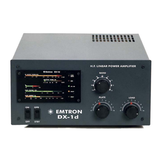
DX-1d
Emtron DX-1d Linear Amplifier Manuals
Manuals and User Guides for Emtron DX-1d Linear Amplifier. We have
1
Emtron DX-1d Linear Amplifier manual available for free PDF download: Operating Manual
Emtron DX-1d Operating Manual (40 pages)
HF LINEAR AMPLIFIER
Brand:
Emtron
| Category:
Amplifier
| Size: 0 MB
Table of Contents
Table of Contents
3
1 General Description
5
D - Internal View
6
2 Technical Specifications
7
3 Unpacking
8
Opening the Carton
8
Opening the DX-1D Cover
8
Removing the Packing Block
8
4 Installation Environment
9
Required Environment
9
Power Requirements
9
5 Rear Panel
9
Power / Earth Connections
9
Rf Connections
9
Transceiver Control
9
6 Front Panel
10
Controls
10
Displays
10
7 Electrical Connections
12
Connections to Transceiver / Exciter
12
Earth and Mains Connections
12
The Power Cable (Export Version)
12
Operation at 230V, 220V, 200V, 100V and 120V (Export Version)
12
8 DX-1D Description
14
Rf Section
14
Mains Transformer
14
Power Supply
14
Soft Start Module
14
Sensor Module
14
Antenna Relay / Qsk Module
14
Display Board
15
Controller Board
15
9 Powering up
16
10 Operation
16
Tunning Procedure
16
General
16
Preliminary Tuning
16
Final Tuning
17
Potential Problems During Tuning
18
Alc Adjustment
18
USING YOUR DX-1D
19
CW / RTTY and All Digital Modes
19
Voice Modes (SSB)
19
Hints on Good Linearity and Efficiency
19
11 Switching the Power off
20
12 Troubleshooting - if Something Goes Wrong
20
No Power
20
Fan Not Working
20
If the FAULT Light Turns on
20
Over-Temperature Cut-Off
20
Over-Current Cut-Off
21
Ig2 Blinks Fast - no Plate Voltage
21
Sparks / Discharges in Rf Area
21
SWR Cut-Off
21
Frequent Over-Drive Protection Cut-Off
21
Tube Replacement
21
13 Warranty / Service
21
14 Glossary
22
15 Appendix 1: Schematic Diagrams
23
D Block Diagram
23
Circuit Diagram - High Voltage Power Supply
24
Control Board and Adjustment Points
25
Circuit Diagram - Ac Input and Wiring Diagram - Standard
26
Circuit Diagram - Ac Input and Wiring Diagram - U.s. Version
27
Circuit Diagram - Soft Start (200 to 240 V Operation)
28
Circuit Diagram - Qsk
29
Circuit Diagram - Rf Module
30
Circuit Diagram - Control Board
31
Control Board - Component Legend (Silkscreen Top)
32
Control Board - Solder Side Track Work
33
16 Appendix 2: Waveforms
34
QSK (Optional Module) Switching
34
Linearity
34
17 Appendix 3: Adjustments
35
Control Board
35
PRE-BIAS ADJUSTMENT (Adjustment: POT7, Marked PRE_BIAS)
35
BIAS ADJUSTMENT (Adjustment: POT3, Marked BIAS)
35
SWR Protection Adjustment
36
EBS ADJUSTMENT (Adjustment: POT4, Marked EBS)
36
SCREEN VOLTAGE ADJUSTMENT (Adjustment: POT2, Marked SCREEN)
36
SCREEN CURRENT LIMIT ADJUSTMENT (Adjustment: POT1, IG2LIMIT)
37
IPTRIP ADJUSTMENT (Adjustment: POT6, Marking: IP TRIP)
37
Display Board Adjustments
39
PLATE CURRENT (Adjustment: VR4, Marked: AMP)
39
PLATE VOLTATE (Adjustment: VR2, Marked: VOLT)
39
REFLECTED POWER (Adjustment: VR3, Marked: RF R)
39
FORWARD POWER (Adjustment: VR1, Marked: RF F)
39
SCREEN CURRENT (Adjustment: VR6, Marked IG2+, VR5, Marked IG2-)
39
Rf Sensor Adjustment
40
Advertisement
Advertisement
Related Products
Emtron DX-3
Emtron DX-3SP
Emtron DX-2
Emtron Categories
Cables and connectors
Amplifier
Monitor
Automobile Accessories
Measuring Instruments
More Emtron Manuals
Login
Sign In
OR
Sign in with Facebook
Sign in with Google
Upload manual
Upload from disk
Upload from URL