
Related Manuals for Emtron DX-2


Summary of Contents for Emtron DX-2
- Page 1 OPERATING MANUAL EMTRON DX-2 HF LINEAR AMPLIFIER Emtron North America Distributed Exclusively in North America By: Emtron North America...
- Page 2 DX-2, Serial No………… INITIAL SETTINGS FOR PLATE AND LOAD CAPACITORS TEST BAND FACTORY SETTINGS USER SETTING FREQUENCY 50 OHM LOAD ANTENNA PLATE LOAD PLATE LOAD 21.200 MHz 18.100 MHz 14.200 MHz 7.070 MHz 3.600 MHz 1.800MHz 160m 1.850 MHz 160m 1.900 MHz...
-
Page 3: Table Of Contents
10.1.3 Final tuning...............................10 10.1.4 Potential problems during tuning......................10 10.2 ALC ADJUSTMENT ..........................10 10.3 USING YOUR DX-2 ..........................11 10.3.1 CW / RTTY and all digital modes......................11 10.3.2 Voice modes (SSB) ............................11 10.3.3 Hints on good linearity and efficiency.......................11 11 SWITCHING THE POWER OFF ........................11 12 TROUBLESHOOTING - IF SOMETHING GOES WRONG ................12... - Page 4 14 GLOSSARY .................................13 15 SERVICE ................................14 15.1 ..............................14 ENERAL 15.1.1 CONTROL BOARD...........................14 15.1.2 DISPLAY BOARD ADJUSTMENTS ......................18 15.1.3 RF SENSOR ADJUSTMENT........................19 16 DIAGRAMS AND SCHEMATICS........................21 16.1 DX-2 B ...........................21 LOCK IAGRAM 16.2 ..............22 ONTROL OARD ONNECTIONS AND DJUSTMENT OINTS 16.3 ....................23...
-
Page 5: General Description
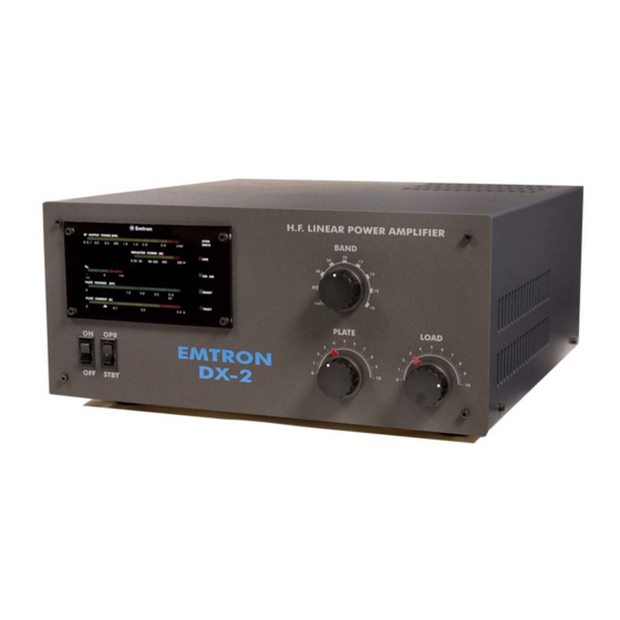
1 GENERAL DESCRIPTION The Emtron DX-2 Linear Amplifier is a 1500 watt carrier output power, for the 160m through 15m amateur bands (7 bands), housed in a desk-top cabinet with self-contained power supply and cooling system. -
Page 6: Internal View
1.1 DX-2 – Internal View The main components of a DX-2 amplifier are shown in the picture below. -
Page 7: Technical Specifications
3 UNPACKING The DX-2 is packed in a heavy duty package easily sufficient to protect the amplifier during transportation, even in case of fairly rough handling. The weight of the commercially rated mains transformer does mean, however, that dropping the amplifier would without... -
Page 8: Opening The Carton
This is an ALC system for use with transceivers or transmitters having a negative-going ALC system and possessing an external ALC input jack. A shielded patch lead with an appropriate connector at one end and a male RCA connector for the DX-2 at the other end is required. -
Page 9: Front Panel
ON Air - single LED, green. When pressing PTT, this LED turns on (while in OPERATE) READY - single LED, yellow. Turns on at the end of warm-up period, when the mains power to DX-2 is switched on. It turns off for about 2 minutes if the plate current protection is triggered. -
Page 10: Electrical Connections
Power connections Before connecting any power to the amplifier, make a good Earth connection to the screw with wing nut at the rear of DX-2. Make sure the POWER switch on the front panel is in the OFF position. Then plug the power cable into the power point. -
Page 11: Terminating The Power Cable (Export Version)
7.4 Operation at 230V, 220V and 200V (export version) The Emtron DX-2 will normally arrive pre-set for the power source of the country the amplifier has been sold to. However if operation to another mains voltage is required, the appropriate connection changes will be needed. -
Page 12: Mains Transformer
5 seconds, avoiding the high inrush current typical for such big loads. 8.5 Sensor module A small metal box positioned at the output of the DX-2. It detects the forward and reverse power, for measurement and display, as well as for SWR monitoring and to activate the protection, when needed. -
Page 13: Powering Up
Start with the transmitter at minimum power, in a "carrier" mode e.g. RTTY or CW - key down. • Key the transceiver ON and gradually apply power to the DX-2. When 0.5 to l W of drive is reached, the EBS is activated and the plate current jumps from zero to about 0.3 - 0.4A •... -
Page 14: Final Tuning
10.2 ALC ADJUSTMENT The DX-2 can be operated without any ALC connection. However, if you wish to use it, and your transceiver has an ALC input, then the potentiometer on the rear panel must be adjusted. This adjustment is not critical, since its voltage output is zero under normal operation and it increases sharply (towards a negative value - up to -11 V), when the overdrive limit is approached. -
Page 15: Using Your Dx-2
See the Appendix 2 and the Troubleshooting section for oscilloscope displays showing examples of a two tone generator driving the DX-2 in linear mode, and an overdrive situation, when a DX-2 with the overdrive protection disabled is being overdriven by the two- tone generator. -
Page 16: Troubleshooting - If Something Goes Wrong
• When you switch on a DX-2, it takes about 3 - 5 seconds for the lights on the front panel display to come on. This is due to the "soft start" circuit. If nothing happens after turning the power on, switch off at the front panel, then check the following: •... -
Page 17: Glossary
See the service section of this manual. 13 WARRANTY I SERVICE The full FOUR YEARS warranty for DX-2 amplifiers covers all parts and labour, except for the tube. The tube is under a limited warranty, also for FOUR YEARS. -
Page 18: Service
15.1 General All Emtron amplifiers are built in a modular for. Most modules are common for the entire DX-n range. This makes it easier to service the amplifier. However, this should only be attempted by suitable qualified people, with proper tools and test equipment. - Page 19 Stop transmitting and replace the 50 ohm dummy load with the special dummy load described above. Switch the dummy load to 140 ohm and key the amplifier for just one second. If the protection wasn’t activated immediately, increase the sensitivity (Rotate clockwise for DX-1, DX-2, and DX-2SP and anti-clockwise for DX-3).
- Page 20 15.1.1.5 SCREEN VOLTAGE ADJUSTMENT (Adjustment: POT2, marked SCREEN) The screen voltage can be measured on the pin marked EG2 on the control board (close to the jumper EBS, this pin has a blue wire connected to it; in DX-3 it is easier to measure on either side of R18). The nominal adjustment is 356V unloaded.
- Page 21 BIAS SCREEN VOLTAGE SENSITIVITY SCREEN EBS OFF CURRENT LIMIT EBS ON PROTECTION PLATE CURRENT PROTECTION EBS OFF SCREEN EBS ON CURRENT LIMIT SENSITIVITY SWR1 SWR4 SCREEN BIAS VOLTAGE PRE-BIAS (Ip0)
-
Page 22: Display Board Adjustments
15.1.2.4 4. FORWARD POWER (Adjustment: VR1, marked: RF F) On 20m, operate the amplifier at the full nominal power, as indicated by an external power meter: 1500W for DX-2 2000W for DX-2SP 3000W for DX-3 Adjust potentiometer “RF F” for correct display indication 15.1.2.5... -
Page 23: Rf Sensor Adjustment
15.1.3 RF SENSOR ADJUSTMENT The amplifier is switched off for this adjustment. Check if adjustment is required as per following procedure, before opening the sensor. Unsolder and remove the metal cover. Connect a transceiver to the input and a dummy load to the output of the amplifier. Connect a voltmeter to pin SW1 or SW2 on the control board (with yellow/black wires). - Page 24 OUTPUT INPUT SIDE SIDE TRIMMER TRIMMER...
-
Page 25: Diagrams And Schematics
16 DIAGRAMS AND SCHEMATICS 16.1 DX-2 Block Diagram POWER DISPLAY MODULE SUPPLY MODULE FAULT ON AIR HV DC HV AC READY RF / TUBE -Eg1 MODULE SWR PROT. SENSOR CONTROL RF In BOARD (From ANT Relay FILAM. or QSK) MODULE... -
Page 26: Control Board Connections And Adjustment Points
16.2 Control Board Connections and Adjustment Points The drawing below shows all the connections to the control board and the adjustment points. Unless you know very well what you are doing and you have a reason to do it, do not modify any adjustment! CONTROL BOARD - Bottom View (Solder side) QSK ONLY... -
Page 27: Display Board Adjustment Points
The drawing below shows the adjustment points on the display board. The display glass has to be removed in order to access these adjustments, on the front panel of the DX-2. Unless you know very well what you are doing and you have a reason to do it, do not modify any adjustment! ALL POTENTIOMETERS: Rotating counter-clockwise will increase the sensitivity and increase the indication. -
Page 28: Circuit Diagram - High Voltage Power Supply
16.4 Circuit Diagram – HIGH VOLTAGE POWER SUPPLY 470uF/450V 6A100 6A100 1000pF 1000pF 330k 6A100 6A100 1000pF 1000pF 470uF/450V 330k 6A100 6A100 1000pF 1000pF 470uF/450V 330k 6A100 6A100 1000pF 1000pF 470uF/450V 330k 6A100 6A100 1000pF 1000pF 470uF/450V 330k 6A100 6A100 1000pF 1000pF 6A100... -
Page 29: Circuit Diagram - Ac Input And Soft Start Wiring - U.s. Version
16.5 Circuit Diagram – AC INPUT and SOFT START WIRING – U.S. version Brown Blue To LOOM (+12V) Brown Blue Brown FEMALE MALE Soft Start Module 120V ACTIVE Brown 200V 4.7nF/250Vac/Y 2 Yellow/Green RELAY DPST EARTH Blue 220V 4.7nF/250Vac/Y 2 Brown Blue Blue... -
Page 30: Circuit Diagram - Rf Module
16.6 Circuit Diagram – RF MODULE R.F. OUT MODULE (Simplified Diagram) PLATE VOLTAGE PLATE CHOKE 2200pF 500pF 1100pF 1000pF/6kV 1000pF/6kV 1000pF/6kV 1000pF/6kV F.O. PROTECTION BOARD A106 A106 A106 A106 A106 A106 A106 GU84B 2.2nF 1N4148 2.2nF 1N4148 140V 140V 1500p SM 275V 140V 2.2k... -
Page 31: Circuit Diagram - Display Board
16.7 Circuit Diagram – DISPLAY BOARD X 3-14 100uF X 3-1 X 3-12 X 3-4 VOLT LM3914 X 3-11 LM3914 LM3914 LM3914 FORWARD POW ER C 12 X 3-8 X 3-9 Ig2- Ig 2+ 47uF LM3914 LM3914 2.nF X 3-2 LM3914 LM3914 47uF... -
Page 32: Ircuit Iagram - Soft Start - 240 Volt Version
16.8 Circuit Diagram – SOFT START – 240 Volt version PHASE LOAD 100/2W 100/2W 220/2W 1N4007 470nF/250Vac/X2 SWITCH 470k/2W 470k/2W 270k 220uF/25V 4.7nF/250Vac/Y 2 220uF/25V 1N4007 2.2nF 2.2nF SWITCH LOAD 56R/2W 100nF 150/2W 56R/2W 100k 100nF 100nF 47nF 3.3uF 220nF/250Vac/X2 2.2nF NEUTRAL GATE... -
Page 33: Circuit Diagram - Qsk
20uF 1N4004 1N4148 Jenings TJ1A-26S NR-HD-16V RF OUT (TO RF SENSOR) RF DECK OUT RF DECK IN RF IN (SO239) E M T R O N Title QSKv2 DX-2 Size Document Number QSK2DX2 Date: Monday , January 07, 2002 Sheet... -
Page 34: Circuit Diagram - Control Board
16.10 Circuit Diagram – CONTROL BOARD... -
Page 35: Control Board - Component Legend
16.11 Control Board – Component Legend EBS OFF... -
Page 36: Control Board - Solder Side Track Work
16.12 Control Board – Solder Side Track work C O P P E R L A Y E R S O L D E R S I D E...
Need help?
Do you have a question about the DX-2 and is the answer not in the manual?
Questions and answers