
Related Manuals for Emtron DX-3SP


Summary of Contents for Emtron DX-3SP
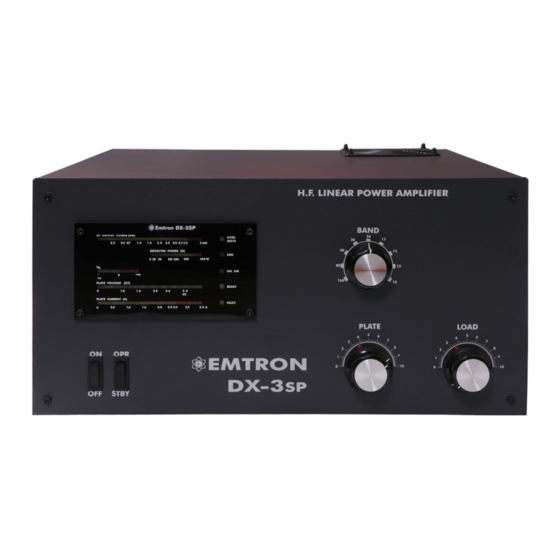
- Page 1 OPERATING MANUAL EMTRON DX-3SP HF LINEAR AMPLIFIER February 2009 Emtron DIVISION OF EMONA ELECTRONICS PTY. LTD. 92-94 Wentworth Avenue, Sydney 2010, Australia Tel. +612 92110988 www.emtron.com.au...
- Page 2 INITIAL SETTINGS FOR PLATE AND LOAD CAPACITORS TEST BAND FACTORY SETTINGS USER SETTINGS FREQUENC 50 OHM LOAD ANTENNA PLATE LOAD PLATE LOAD 28.600 MHz 24.900 MHz 21.200 MHz 18.100 MHz 14.200 MHz 10.125 MHz 7.070 MHz 3.600 MHz 1.800 MHz 160m 1.850 MHz 160m...
-
Page 3: Table Of Contents
Preliminary tuning ..............................18 10.1.3 Final tuning ................................19 10.1.4 Potential problems during tuning..........................20 10.2 USING YOUR DX-3SP ..............................20 10.2.1 CW / RTTY and all digital modes ..........................20 10.2.2 Voice modes (SSB)..............................20 10.2.3 Hints on good linearity and efficiency........................21... - Page 4 WARRANTY / SERVICE ..............................23 GLOSSARY ..................................24 APPENDIX 1: SCHEMATIC DIAGRAMS ........................25 15.1 ................................25 LOCK IAGRAMS 15.1.1 DX-3SP Block Diagram ............................25 15.1.2 AC INPUT AND WIRING DIAGRAM........................26 15.2 ................................27 IRCUIT IAGRAMS 15.2.1 SOFT START Single Phase – Circuit Diagram ......................27 15.2.2...
-
Page 5: General Description
CW or the digital modes. Operation of the DX-3SP is greatly simplified by the absence of meter switching and of front panel level setting controls. The front panel moving LED display systems indicate simultaneously: the output forward and reverse power, screen grid current (positive and negative), the plate voltage and the plate current, while 5 single LED’s indicate: Ready, Overdrive warning, High SWR cut-off indication, On Air and Fault. -
Page 6: Dx-3Sp - Internal View
1.1 DX-3SP – Internal View The main components of a DX-3SP amplifier are shown in the picture below. BLOWER Mains Isolation ANT. RELAY Relay (QSK) SOFT START RF CHOKE Coupling CONTROL RF SENSOR Capacitor Temperature Sensors BOARD TERMINAL BLOCK PRIMARY WIRING... -
Page 7: Technical Specifications
The fan speed control temperature sensor has a nominal value of 80° (176F). OPERATIONAL PROTECTION • Overdrive protection: Should the DX-3SP be overdriven, a LED warning indicator will light up when the linearity limit is reached. If the drive is increased further, a 2 second cut off (by-pass) will follow. - Page 8 METERING: The front panel moving LED display systems indicate: “Moving light” LED indicators: • output power • reflected power • screen grid current (positive / negative) • plate voltage • plate current Five single LED’s: • on air • ready •...
-
Page 9: Unpacking
Make sure the transformer is wired for the nominal mains voltage in your area. See 7.4. Two people are needed to install the transformer. The best is to put the DX-3SP on a flat, smooth surface such as a bench or a table-top, covered by a small carpet of a folded blanket, so that it can be moved by sliding it on the table. -
Page 10: Installation Environment
However, the wiring of the mains supply for the amplifier should be able to handle the power at full load with minimal drop in the voltage, to insure the performance of your DX-3SP does not suffer. -
Page 11: Front Panel
STBY position until the amplifier is ready to operate. 5.2 Displays All the DX-3SP indicators are concentrated in a single, “moving light” display (See Fig. 4). The following values are displayed (top to bottom): Output Power - Scale up to 5 kW, non linear. -
Page 12: Rear Panel
ON Air - single LED, green. When pressing PTT, this LED turns on (while in OPERATE and READY). READY - single LED, yellow. Turns on at the end of warm-up period, when the mains power to DX-3SP is switched on. It turns off for about 2 minutes if the plate current protection is triggered. In this case, the FAULT light also turns on. -
Page 13: Electrical Connections
7.1 Connections to Transceiver / Exciter Signal connections Before making any connections, ensure that DX-3SP is not connected to AC power, and the transceiver is not transmitting. Connect the antenna first to the DX-3SP output. Then connect the transceiver output to the DX- 3SP RF input. - Page 14 PLEASE NOTE: The DX-3SP should not be connected to a mains supply of less than 200VAC! Move the thick brown wire to 240, 230, 220 or 200V. Leave the thin brown wire on 240V Figure 6 Wiring for 230V shown as example...
-
Page 15: Dx-3Sp Description
8 DX-3SP DESCRIPTION 8.1 RF Section The RF section occupies the right hand side of the DX-3SP (looking from the top - front). See picture in 1.1. RF Switch and tuned circuits At the front of the amplifier are two variable capacitors, for plate and load tuning. A 9-position ceramic switch is employed for the 9 operating bands. -
Page 16: Antenna Relay / Qsk Module
2 seconds. It ensures a clean signal, making it virtually impossible to overdrive the DX-3SP. • SWR detector and timer - switches the amplifier to bypass mode for about 3 seconds when high SWR is detected. -
Page 17: Powering Up
Switch now the mains power ON (The power switch to ON position). The "soft start" system will take about 5 seconds to fully turn the power on. SWR light will turn on briefly, then off. Wait for the DX-3SP to warm up, until the READY light turns on. -
Page 18: General
• Start with the transmitter at minimum power, in a "carrier" mode e.g. RTTY or CW - key down. • Key the transceiver ON and gradually apply power to the DX-3SP. When 0.5 to l W of drive is reached, the EBS is activated and the plate current jumps from zero to about 0.5 A. -
Page 19: Final Tuning
3. During the preliminary tuning, switch PTT on and off several times, to allow time for tube cooling. The tube dissipation (at a given drive level) is minimum when tuning is optimum. In short, be brief, with tuning "bursts". 4. Preliminary tuning, as described above, is only necessary when operating for the first time in a certain band. When the final settings for PLATE and LOAD have been found for the particular working conditions - especially the antenna used, note your settings on Table 1. -
Page 20: Potential Problems During Tuning
• If the SWR protection cuts in – it is likely to be a problem with either the feedline, antenna or associated antenna switching components. In principle, the SWR protection level in DX-3SP is adjustable, but it is far preferable for you to fix your antenna system. -
Page 21: Hints On Good Linearity And Efficiency
12.1 No power When you switch on a DX-3SP, it takes about 3 - 5 seconds for the lights on the front panel display to come on. This is due to the "soft start" circuit. If nothing happens after turning the power on, switch off at the front panel,... -
Page 22: Fan Not Working
If it is still not working, unplug the power cord from the mains, then remove the fuses from the fuse holders on the rear panel of DX-3SP and check them with an ohmmeter. If a fuse is blown, replace it with a fuse of the same type and try again. -
Page 23: Sparks / Discharges In Rf Area
The factory adjustment for SWR protection is about 2.6: 1. This adjustment can be changed, but the best is to operate with a properly matched antenna. Should your DX-3SP 'see' bad SWR, it will shut down for 3 seconds (in bypass mode). -
Page 24: Glossary
14 GLOSSARY Alternating Current Automatic Level Control Amplitude Modulation BALUN Balanced / Unbalanced Transformer Bayonet Neil-Concelman Connector Continuous Wave decibel Direct Current Electronic Bias Switch Frequency Modulation High Frequency High Voltage International Electro-technical Commission Inter-Modulation Distortion Light Emitting Diode Peak Envelope Power Radio Frequency RTTY Radio Tele Type... -
Page 25: Appendix 1: Schematic Diagrams
15 APPENDIX 1: SCHEMATIC DIAGRAMS 15.1 Block Diagrams 15.1.1 DX-3SP Block Diagram DX-2sp Block Diagram Back Front Temp Fans Panel panel sensor Soft start On/Off switch Line 1 Primary 30 amp fuse Stby/Opr power Control Line 2 switch cord board... -
Page 26: Ac Input And Wiring Diagram
Brown To LOOM (+12V) Blue Brown FEMALE MALE 120V LINE 1 Soft Start Module (Phase) Brown Rear Panel 200V 4.7nF/250Vac/Y 2 Yellow/Green RELAY Brown Neutral/Ground 4.7nF/250Vac/Y 2 220V Black Blue Blue Rear Panel LINE 2 230V BTA40-600B (Neutral) (On Chassis) Yellow Blue 240V... -
Page 27: Circuit Diagrams
PHASE 470nF/250Vac/X2 LOAD 220/2W 1N4007 (TRANSFORMER) 470k/2W SWITCH 270k 470k/2W 100/2W 100/2W 4.7nF/250Vac/Y2 220uF/25V 220uF/25V 2.2nF 2.2nF 1N4007 SWITCH 110V 200-240V 3.9k/5W NOT INSTALLED 56R/2W LOAD (TRANSFORMER) 100nF 100k 150/2W 56R/2W 47nF 100nF 100nF GATE 220nF/275Vac/X2 3.3uF NEUTRAL 2.2nF 4.7nF/250Vac/Y2 NOTE: For 110VAC operation add R11 and move jumper to 110V position... -
Page 28: High Voltage Power Supply - Circuit Diagram
15.2.2 HIGH VOLTAGE POWER SUPPLY – Circuit Diagram Figure 10... -
Page 29: Rf Module Simplified
15.2.3 RF Module Simplified To QSK PLATE VOLTAGE switching (Simplified Diagram) R.F. OUT MODULE 1000pF/6kV 1000pF/6kV 1000pF/6kV 1000pF/6kV PLATE CHOKE 2200pF 3x150 500pF 1100pF 3x150 CONTROL BOARD SAFETY CHOKE A106 A106 A106 A106 A106 FU-728F FU-728F 10nF/1kV 100/13W 100/13W 330/13W 1N4148 140V 140V... -
Page 30: Rf Output Circuit
15.2.4 RF output circuit ANTENNA RF SENSOR Switching L1 (RF COIL) L2 (Torroid) PLATE 3300pF/10kV SW1-1 SW1-2 1100pF 1500pF SW1-3 250pF 50pF 47pF 470pF Figure 12... -
Page 31: Qsk - Circuit Diagram
1N4148 1N4148 1N4148 COAXIAL CABLE (thick) 1N4148 22uF 1N4148 Jenings TJ1A-26S 1N4004 NR-HD-16V COAXIAL CABLE (thick) RF OUT (TO RF SENSOR) 10uF RF DECK OUT 100/1W COAXIAL CABLE (thin) RF DECK IN COAXIAL CABLE (thin) RF IN (SO239) E M T R O N Title QSKv3 DX-2 Size... -
Page 32: Rf Sensor
15.2.6 RF Sensor 10pF 10pF 22/2W 22/2W 10pF D1N4148 D1N4148 10pF 40pF 40pF 47pF 220pF 220pF 47pF 2.2k 2.2k 10nF 10nF Figure 14... -
Page 33: Display Board - Circuit Diagram
X 3-14 100uF X 3-1 X 3-12 X3-4 VOLT LM3914 X 3-11 LM3914 LM3914 LM3914 FORWARD POW ER X3-8 X3-9 47uF Ig2- Ig 2+ LM3914 LM3914 2.nF X 3-2 LM3914 LM3914 47uF X 3-6 2.2nF SWR/FLT X 3-3 X 3-15 FAULT 2.2nF X 3-13... -
Page 34: Control Board - Circuit Diagram
15.2.8 CONTROL BOARD – Circuit Diagram Figure 16... -
Page 35: Control Board And Adjustment Points
15.3 Control Board and Adjustment Points The drawing below shows all the connections to the control board and the adjustment points. Unless you know very well what you are doing and you have a reason to do it, do not modify any adjustment! GRY/BLK Y/GRN BLUE... -
Page 36: Control Board Component Layout
15.3.1 Control Board Component Layout Figure 18... -
Page 37: Control Board - Solder Side Track Work
15.3.2 Control Board – Solder Side Track work Figure 19... -
Page 38: Appendix 2: Waveforms
16 APPENDIX 2: WAVEFORMS 16.1 QSK Switching Figure 20 No “Hot switching”: The output relay (Top trace) switches first, and then the RF drive is applied (Bottom trace) 16.2 Linearity Linear Trapezoid Modulation Pattern Figure 21 Sample of linearity curve obtained by using a two-tone generator and a PC oscilloscope in XY mode. -
Page 39: Appendix 3: Adjustments
17 APPENDIX 3: ADJUSTMENTS ADJUSTMENTS TO EMTRON DX-3SP AMPLIFIERS CAUTION Most of the following adjustments require the amplifier to be open and powered up. This also implies defeating the mains interlock safety switch, which is extremely dangerous since high voltage / high power DC and AC and RF voltages are exposed. -
Page 40: Swr Protection Adjustment
There are 3 bias adjustment potentiometers: POT3 (BIAS), affecting both tubes and POT10 (BS1) and POT9 (BS2) only adjusting the bias to the tube connected to the pins BS1 and BS2 respectively. Adjust initially POT10 and POT9 fully clockwise, then rotate back about 20 degrees (they are likely to be already in the required position). -
Page 41: Ebs Adjustment
17.1.4 EBS ADJUSTMENT Adjustment: POT4, marked EBS Usually this adjustment is performed on 20m (14.200 MHz), but it can be done on any band. Transmit into a dummy load or antenna. Apply very low input drive. With the EBS activated (with the EBS jumper in the forward position, or ON): Checking the existing adjustment: increase slowly the input drive, starting from zero, until the EBS system activates the amplifier. -
Page 42: Iptrip Adjustment
the EG2 pin on the control board. While operating the amplifier at full power, by rotating the LOAD knob, IG2 can be varied and the screen voltage can be measured. This way the current limit of the screen regulator and the ig2 indicator on the front panel can be checked quickly, without the need for a special load. -
Page 43: Display Board Adjustments
BIAS PRE-BIAS SENSITIVITY EBS ON EBS OFF SCREEN VOLTAGE Ip PROTECTION SCREEN CURRENT LIMIT Figure 22 Control Board – Component side view 17.2 Display Board Adjustments The display board is pre-adjusted during testing. However, when a new display board is installed in the amplifier, most adjustments need to be fine-tuned. -
Page 44: Plate Voltage
Adjust potentiometer AMP for correct indication. 17.2.2 PLATE VOLTAGE Adjustment: VR2, marked: VOLT Using a voltmeter with a high voltage probe, measure the plate voltage. Adjust potentiometer VOLT for correct indication on the display. 17.2.3 REFLECTED POWER Adjustment: VR3, marked: RF R Make sure the amplifier is in STANDBY. -
Page 45: Rf Sensor (Bridge) Adjustment
17.3 RF Sensor (Bridge) Adjustment The amplifier is switched off for this adjustment. Check if adjustment is required as per following procedure, before opening the sensor. Unsolder and remove the metal cover. Connect a transceiver to the input and a dummy load to the output of the amplifier. Connect a voltmeter (+) to pin SW1 or SW2 on the control board (with yellow/black wires). - Page 46 Emtron DIVISION OF EMONA ELECTRONICS PTY. LTD. 92-94 Wentworth Avenue, Sydney 2010, Australia Tel. +612 92110988 www.emtron.com.au...
Need help?
Do you have a question about the DX-3SP and is the answer not in the manual?
Questions and answers