
Subscribe to Our Youtube Channel
Related Manuals for Julabo FP51-SL


Summary of Contents for Julabo FP51-SL
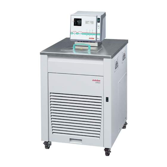
- Page 1 English Operating Manual Ultra-Low Refrigerated Circulator FP51-SL JULABO USA, Inc. 884 Marcon Boulevard Allentown, PA 18109 Phone: +1(610) 231-0250 Fax: +1(610) 231-0260 info.us@ julabo.com www.julabo.com 19532823-V5.doc 23.03.16...
- Page 2 Congratulations! You have made an excellent choice. JULABO thanks you for the trust you have placed in us. This operating manual has been designed to help you gain an understanding of the operation and possible applications of our circulators. For optimal utilization of all functions, we recommend that you thoroughly study this manual prior to beginning operation.
-
Page 3: Table Of Contents
FP51-SL TABLE OF CONTENTS Operating manual ........................ 5 Intended use ......................... 5 1.1. Description ....................... 5 Operator responsibility – Safety recommendations ............6 2.1. Disposal ........................8 2.2. Technical specifications ................... 9 Operating instructions ....................... 11 Safety notes for the user ..................... 11 3.1. - Page 4 12.4. Status messages ....................86 12.5. Error messages....................... 86 13. Installation of electronic module with analog connectors ..........87 14. JULABO Service – Online remote diagnosis ............... 88 15. Cleaning / repairing the unit ..................89 16. WARRANTY PROVISIONS ..................90...
-
Page 5: Operating Manual
Operating manual Intended use JULABO circulators have been designed to control the temperature of specific fluids in a bath tank. The units feature pump connections for temperature control of external systems (loop circuit). JULABO circulators are not suitable for direct temperature control of foods, semi- luxury foods and tobacco, or pharmaceutical and medical products. -
Page 6: Operator Responsibility - Safety Recommendations
Operator responsibility – Safety recommendations Operator responsibility – Safety recommendations The products of JULABO ensure safe operation when installed, operated, and maintained according to common safety regulations. This section explains the potential dangers that may arise when operating the circulator and also specifies the most important safety precautions to preclude these dangers as far as possible. - Page 7 Warning label W26: Colors: yellow, black Hot surface warning. (The label is put on by JULABO) Observe the instructions in the manuals for instruments of a different make that you connect to the circulator, particularly the respective safety recommendations. Also observe the pin assignment of...
-
Page 8: Disposal
Operator responsibility – Safety recommendations 2.1. Disposal The circulator contains a back-up battery that supplies voltage to memory chips when the unit is switched off. Do not dispose of the battery with household waste! Depending on battery regulations in your country, you might be obliged to give back used or defect batteries to gathering places. -
Page 9: Technical Specifications
FP51-SL 2.2. Technical specifications Ultra-Low Refrigerated Circulator FP51-SL Working temperature range °C -51 ... 200 Temperature stability °C ±0,05 Cooling capacity °C -20 -40 Medium: ethanol 2.0 1.5 1.0 0.26 Cooling compressor 1-stage Refrigerant R507 Overall dimensions (WxDxH) 46x55x89 Bath opening... - Page 10 Operator responsibility – Safety recommendations Electrical connections: External alarm device 24-0 V DC / max. 25 mA Computer interface RS232 or RS485 External Pt100 sensor Optional for HL, SL (Order No. 8900100 Electronic module with analog connections) Programmer input -100 °C to 400 °C = 0 - 10 V or 0 - 20 mA or 4 - 20 mA Input for the signal of a flow meter or external manipulated variable Temperature recorder outputs 0 - 10 V (0 V = -100 °C, 10 V = 400 °C)
-
Page 11: Operating Instructions
FP51-SL Operating instructions Safety notes for the user 3.1. Explanation of safety notes In addition to the safety warnings listed, warnings are posted throughout the operating manual. These warnings are designated by an exclamation mark inside an equilateral triangle. “Warning of a dangerous situation (Attention! Please follow the documentation).”... -
Page 12: Safety Recommendations
Safety notes for the user 3.3. Safety recommendations Follow the safety instructions to avoid personal injury and property damage. Also, the valid safety instructions for workplaces must be followed. • Only connect the unit to a power socket with an earthing contact (PE – protective earth)! •... - Page 13 FP51-SL Caution: The temperature controlling i.e. of fluids in a reactor constitutes normal circulator practice. We do not know which substances are contained within these vessels. Many substances are: • inflammable, easily ignited or explosive • hazardous to health •...
-
Page 14: Operating Controls And Functional Elements
Operating controls and functional elements Operating controls and functional elements Front view Rear view Mains power switch, illuminated for circulator Mains power switch, illuminated for cooling machine VFD COMFORT-DISPLAY Header: Control indicators Line 1: Actual value internal or external The display is depending on the selected control mode in the menu >... - Page 15 FP51-SL (providing EPROG input set to >Flow rate<) *refer to >MENU / CONFIGIGURATIO> page 32 Control indicators in the header: Heating / Cooling / Alarm / emote control Control indicators in the header: Temperature indication Internal or External actual value Temperature indication in °C or °F...
- Page 16 Operating controls and functional elements Keypad 1 Navigation keys 1. Key: >OK< Start / Stop (pump / heater ) 2. >OK< in the menu Menu item / select submenu for setting Save set value Save selected parameter A beep signals the end of setting After the actions Start, Stop and change from VFD Display to standard display the key is locked for a short time.
- Page 17 Socket for external measurement and control sensor or external setpoint programming ext Pt100 Interface RS232 / RS485: remote control via personal computer SERIAL Control cable of JULABO refrigerated circulator Socket: output for alarm messages Socket: Option: Electronic module Order No. 8 900 100 The circulator automatically recognizes the connected electronic module.
-
Page 18: Preparations
Preparations Preparations 5.1. Installation • Place the unit on an even surface on a pad made of non-flammable material. Using the castors move the unit to the intended location. For better stability, apply the holding breaks on the front casters. •... - Page 19 Fire or other dangers when using bath fluids that are not recommended: Use only non-acidic and non-corroding bath fluids. JULABO assumes no liability for damage caused by the selection of an unsuitable bath liquid. Unsuitable bath fluids are fluids which, e.g., •...
-
Page 20: Temperature Application To External Systems
Differing flow rates of the pressure and suction pumps should be compensated. To maintain a constant liquid level, the JULABO „D+S“ Level Adapter is recommended for the external bath tank. The flow rate of the pressure pump will be then regulated by a built-in float device. -
Page 21: Tubing
FP51-SL Backflow safety device If the liquid levels in the circulator bath and the external SERIAL ALARM STAND-BY REG+ Pt100 E-PROG system are at different heights, overflowing must be prevented after the power has been turned off. T16A T16A Flood hazard! T1.25A... -
Page 22: Filling / Draining
Preparations Safety recommendations • Employ suitable connecting tubing. • Make sure that the tubing is securely attached. • Avoid sharp bends in the tubing, and maintain a sufficient distance from surrounding walls. • Regularly check the tubing for material defects (e.g. for cracks). •... -
Page 23: Operating Procedures
FP51-SL Operating procedures 6.1. Power connection Caution: • Only connect the unit to a power socket with earthing contact (PE – protective earth)! • The power supply plug serves as safe disconnecting device from the line and must be always easily accessible. -
Page 24: Switching On The Cooling Machine
Operating procedures Selecting the language: There are two options for the language of the LCD DIALOG-DISPLAY: German or English. Select the desired language in the menu >Configuration< under the submenu >Language/Sprache<. Press the respective keys in the following order: 3x up to menu Configuration 6x up to submenu >Language/Sprache<... -
Page 25: Setting Of Temperatures
FP51-SL Setting of temperatures Press the key to call up the menu for temperature selection. 3 different working temperatures can be adjusted. Their values are freely selectable within the operating temperature range. The temperatures can be set in start or stop mode. - Page 26 Safety installations, warning functions Warning: The excess temperature protection must be set at least 25 °C below the fire point of the bath fluid used! In case of wrong setting there is a fire hazard! We disclaim all liability for damage caused by wrong settings! SafeTemp: Setting range: 20 °C ...
- Page 27 FP51-SL The following error message appears on the VFD COMFORT-DISPLAY: for help on the LCD Press Depending on the setting of >ControlType - internal or external< the actual temperature values for both sensors are shown/indicated on both displays.
- Page 28 Safety installations, warning functions • Setting >WARNING< A mere warning function with optical and audible warning signal (interval tone) A message appears on the VFD COMFORT-DISPLAY: OverTemp SubTemp The LCD –DISPLAY shows the message: • Setting >ALARM< Temperature limit with shutdown of heater and circulating pump. An audible alarm sounds (continuous tone) and a message appears on the VFD COMFORT-DISPLAY: OverTemp...
-
Page 29: Early Warning System, Low Level Protection
FP51-SL 8.0.1. Early warning system, low level protection This low level protection is independent of the control circuit and is divided into two sections: . 1. Switch in stage 1 recognizes a critical fluid level DBGM: 20306059.8 An audible warning (interval tone) sounds and a message appears on the VFD COMFORT-DISPLAY. -
Page 30: Menu Functions
Menu functions Menu functions The term „menu functions“ refers to adjustments such as Menu level 1 Start program Page 32 This menu will start a previously set program. Administration and creation of programs Page 37 Electronically adjustable pump capacity Page 41 The capacity of the circulating pump is set by adjusting the motor speed. - Page 31 FP51-SL Menu level 1 Adjustable interface parameters Page 55 BAUDRATE, PARITY, HANDSHAKE ATC - Absolute Temperature Calibration, Page 56 Sensor calibration internal sensor, Sensor calibration external sensor 3-point calibration Limitations of temperature and capacity Page 63 Setpoint Max / Min - Maximum and minimum setpoint Heating Max –...
-
Page 32: Start Of A Program
Menu functions 9.1. Start of a program The start menu of the integrated programmer allows one of six previously stored temperature programs to be called up and started. The profiles are started manually or via the integrated timer. Requirements: 1. - Page 33 FP51-SL Level 2 Parameter /Value • Set desired parameters with Confirm >now< with the key and the program will start immediately start at the set time under parameter (time ). Set time in the example below: 09. August 2009, 11:15 hrs ...
-
Page 34: Status At The End Of A Program
Menu functions 9.1.1. Status at the end of a program Program end StdBy , PSetp, Setp 1, Setp 2 , Setp 3 This parameter is used to determine if the unit switches to the -OFF- condition at the end of a profile or if temperature control is continued, and the working temperature setpoint that is to be used if temperature control is continued. -
Page 35: Editing After Start
FP51-SL 9.1.3. Editing after Start The programmer allows a running program to be edited. Initiation and exit of the editing function: • After the start enter the submenu „3 EDITOR“.by pressing the key See chapter „program administration, creation“ page 37 •... -
Page 36: Interruption After A Power Failure
Menu functions 9.1.5. Interruption after a power failure It is possible to operate the programmer safely in case of a power failure. Important: For this, >Autostart< needs to be set in the >Configuration< menu. If the AUTOSTART function is activated, the programmer starts again at a point approx. -
Page 37: Program Administration, Creation
FP51-SL 9.2. Program administration, creation The integrated programmer permits fast and easy programming of setpoint temperature sequences. This temperature sequence is called program. A program is composed of individual sections (Step). The sections are defined by duration (t) or Gradient (°/t) and target temperature. - Page 38 Menu functions Editing PrgNr: Set the program you wish to create. 0 ... 5 SP : Setpoint TI : Time [hh:mm] or GRD: Gradient [°/t] = [°/min] Change type of program in MENU >configuration<, menu item >Programmtyp/program type< . ...
- Page 39 FP51-SL Delete It is possible to delete an entire program or consecutive sections Delete PrgNr: Set the program you wish to delete 0 ... 5 Delete from Step X to Step X - (0 … 59) Press the key if a parameter is to be retained. (prior to OK) ...
- Page 40 Menu functions Print Every program can be printed via the serial interface for control and documentation purposes. Press the key if a parameter is to be retained. (prior to OK) Submenu >Print< Level 2 • Set menu item >Print PrgNr.< by pressing •...
-
Page 41: Setting The Pump Pressure
FP51-SL 9.3. Setting the pump pressure The capacity of the circulating pump is set by adjusting the motor speed Press the key if a parameter is to be retained. (prior to OK) Submenu >Pump< Level 2 The set pump stage is displayed. Example: 1 •... -
Page 42: Configuration
Menu functions 9.4. Configuration Press the key if a parameter is to be retained. (prior to OK) Level 2 Parameter level Remote control via serial interface. Possible parameters: off / on Switch on and off remote control by pressing ... - Page 43 FP51-SL Level 2 Parameter level Pump-Mode Possible parameters: P. on / P. off • Switch on and off >Off-Mode by pressing P.on continuous operation of circulating pump P.off circulating pump is linked to Start/Stop ActVar - actuating variable Possible parameters: control, Eprog, serial ...
- Page 44 Menu functions Level 2 Parameter level Reset • Return to factory settings by pressing >Reset?< returns all set values to the factory setting except for date and time. A RESET can be effected only in the – OFF- mode. ...
-
Page 45: Remote Control Via The Serial Interface
FP51-SL 9.4.1. Remote control via the serial interface Factory setting: off Setpoint is set via the serial RS232/RS485 interface through a PC or superordinated data system. In the header of the VFD COMFORT-DISPLAY, an “ ” illuminates. It indicates that remote control mode is active. -
Page 46: Autostart
- Autostart off (Factory setting) Note: The circulator has been configured and delivered by JULABO according to N.A.M.U.R. recommendations. This means for the start mode that the unit must enter a safe operating state after a power failure (non- automatic start mode). -
Page 47: Actvar - Actuating Variable
FP51-SL 9.4.5. ActVar - actuating variable The variable (ACTuating VARiable) corresponds to the extent to which the heater or cooling unit of the circulator is controlled. Heat or cold is applied to the bath according to this variable. If this happens with the control electronics of the circulator, called >... -
Page 48: Setting Of Clock And Date
Menu functions 9.4.6. Setting of clock and date The internal real time clock allows starting a program any time. The clock is set to the local mean time (MEZ) at the factory. If the unit is operated in a different time zone, the clock can be adjusted in this menu. -
Page 49: Control
FP51-SL 9.5. Control The circulator is designed for internal and external temperature control. This can be switched in this submenu. Only the set of parameters corresponding to the particular setting is displayed. Control internal Control external For external temperature control and measurement connect a Pt100 external sensor to the socket at the rear of the circulator. - Page 50 Menu functions Control Type internal Parameter-Level • The value flashes. Set by using the numeric keypad and confirm by pressing Example: Setting range: 0.1 … 99.9 K • The value flashes. Set by using the numeric keypad and confirm by pressing Setting range: 3 …...
-
Page 51: Control Internal / External
FP51-SL 9.5.1. Control internal / external The control type can be adjusted in the -OFF- mode only. Possible parameters: intern internal temperature control extern external temperature control with external Pt100 sensor IMPORTANT: Additional measures for external temperature control. ext. -
Page 52: Selftuning
Menu functions 9.5.2. Selftuning When performing a selftuning for the controlled system (temperature application system), the control parameters Xp, Tn and Tv are automatically determined and stored. Possible parameters: off - no selftuning The control parameters ascertained during the last identification are used for control purposes. -
Page 53: Cospeed - Extern
FP51-SL 9.5.4. CoSpeed - extern CoSpeed: This parameter affects the temperature pattern only in case of external control. Possible parameters: 0 ... 5 During selftuning, the control parameters Xp, Tn, °C Int. temperature and Tv of a controlled system are automatically determined and stored. - Page 54 Menu functions Optimization instructions for the PID control parameters: optimum setting The heat-up curve reveals inappropriate control °C settings. Inappropriate settings may produce the following heat-up curves: Xp too low Tv/Tn too low °C °C Xp too high or Tv too high Tv/Tn too high or Xp too high °C °C...
-
Page 55: Serial Interface
FP51-SL 9.6. Serial Interface For communication between the circulator and a PC or a superordinated Factory settings: process system, the interface parameters of both units must be identical. 4800 Baud The adjustment is usually carried out one time only in the >Interface serial<... -
Page 56: Atc Absolute Temperature Calibration, 3-Point Calibration
Menu functions 9.7. ATC Absolute Temperature Calibration, 3-point calibration ATC is used to compensate for a temperature difference between the circulator and a defined measuring point in the bath tank that may develop for physical reasons. internal external Principle: For ATC calibration, in steady state the bath temperature at the location Example: of the temperature sensor (CT) is determined at the respective adjusted 1-point calibration... - Page 57 FP51-SL Press the key if a parameter is to be retained. (prior to OK) Level 2 Parameter-Level • The parameter flashes, switch by pressing The parameter flashes, switch by pressing >no< Carry out an ATC calibration ...
- Page 58 Menu functions The value >TmpValue< is only indicated In addition the measured temperature value >CalValue X< is saved during the next step. • The value flashes. Set by using the numeric keypad and confirm by pressing If only a 2-point calibration is carried out, the following menu items are not indicated anymore The value >TmpValue<...
-
Page 59: Atc Fühler - Intern / Extern
FP51-SL 9.7.1. ATC Fühler - intern / extern In the first submenu the ATC function is set for the >intern< internal or the >extern< external temperature sensor. Calibration can be carried out for the internal temperature sensor and for the external temperature sensor connected to the socket „ext. Pt100“. -
Page 60: Example: 3-Point Calibration For Internal Control
Menu functions 9.7.4. Example: 3-point calibration for internal control In the temperature range from 80 °C to 160 °C the calibration curve of the temperature sensor (TT) is to be adjusted to the actual temperatures at measuring point (CT). 1. Set circulator to internal control: ... - Page 61 FP51-SL The value >TmpValue< is only indicated. In addition the measured temperature value >CalValue X< is saved during the next step. • The value flashes. Set by using the numeric keypad and confirm by pressing Return to 2. Set working temperature value: 120.00 °C The value >TmpValue<...
-
Page 62: Limits
Menu functions 9.8. Limits The >Limits< menu allows the minimum and maximum values to be set for all important setting ranges and capacity variables. Control internal Control external Press the key if a parameter is to be retained. (prior to OK). ... -
Page 63: Limits For Internal Control And External Control
FP51-SL • The parameter flashes. Set by using the numeric keypad and confirm by pressing • The parameter flashes. Set by using the numeric keypad and confirm by pressing • The parameter flashes. Set by using the numeric keypad and confirm by pressing ... -
Page 64: Limits For External Control
Menu functions 9.8.2. Limits for external control INTERN MAX / MIN Restriction for the temperature range of the internal bath. Setting range: -94,9 °C ... +300,0 °C The limits IntMax and IntMin are only active in external control. IntMax and IntMin determine fixed limits for the temperature within the internal bath. -
Page 65: Analog Inputs/Outputs
FP51-SL 9.9. Analog inputs/outputs In order to use the analog inputs and outputs, the circulator must be equipped with the electronic module, which is available as option. Order No. 8 900 100 Electronic module ALARM STAND-BY REG+ E-PROG This submenu enables the input and output values to be set for the programmer input and the temperature recorder outputs of the REG+E- PROG socket. - Page 66 Menu functions Level 2 Level 3 Parameter-level Define the output value for channel 1 Possible parameters: ActInt, ActExt, Power, Setpoint • The parameter flashes, switch by pressing Select the scale for channel 1. • The value flashes. Set by using the numeric keypad and confirm by pressing •...
- Page 67 FP51-SL Level 2 Level 3 Parameter-level Define the output value for channel 3 Possible parameters: ActInt, ActExt, Power, Setpoint • The parameter flashes, switch by pressing Select the scale for channel 3. • The value flashes. Set by using the numeric keypad and confirm by pressing •...
- Page 68 Menu functions Level 2 Level 3 Parameter-level Possible parameters: voltage, current • The parameter flashes, switch by pressing • The value flashes. Set by using the numeric keypad and confirm by pressing • The value flashes Set by using the numeric keypad and confirm by pressing ...
-
Page 69: Control Connector
FP51-SL Level 2 Level 3 Parameter-level Possible parameters: normal, inverse • The parameter flashes, switch by pressing 9.9.1. Control connector Control connector (14): SV-Out >Backflow< or >C-Pulse< or >Refill< The control output (14) can be adapted to solenoid valves for different tasks. -
Page 70: Outputs Of The Connector - Reg+E-Prog
Menu functions 9.9.2. Outputs of the connector - REG+E-PROG Outputs of the connector 1. First define the desired output value for channels 1 to 3: ActInt internal actual temperature value (bath temperature) ActExt external actual temperature value (external sensor) Power periodic or intermittent heating or cooling Setpoint active setpoint temperature (setpoint 1, 2, 3/integr. -
Page 71: Input Of The Connector - Reg+E-Prog
FP51-SL 9.9.3. Input of the connector - REG+E-PROG E-PROG - Input Setting is necessary if Menu >Configuration< 1. the Setpoint is to be set via an external voltage or current source or programmer For this, in the menu >Configuration<, first set the menu item >Setpoint<... - Page 72 Menu functions After returning the LCD display to standard display by pressing the , the temperature value adjusted and set on the external voltage or current source is displayed in line 1 (Example: Eprog 50.00 °C). This EPROG input enables the use of different voltage and current values as program parameters.
-
Page 73: External Stand-By Input
FP51-SL 9.9.4. External Stand-by input Ext. StBy (External STAND-BY input) Stand-By input for external switch-off. Possible parameters: inactive - Stand-By input is ignored active - Stand-By input is active Activate the standby input: 1. Under menu item >Ext. StBy<, set the parameter to >active<. -
Page 74: Alarm-Output
Menu functions 9.9.5. Alarm-output Alarm output (10) (for external alarm signal) This socket is a potential-free change-over contact. With the adjustments in the menu >Inputs/Outputs<, all operating conditions can be signaled without having to change the pin assignments. Meaning of the terms under menu item >Function< : ALARM The circulator is in condition >StandBy<... -
Page 75: Troubleshooting Guide / Error Messages
The float is defect (e. g., because damaged in transit). Repair by authorized JULABO service personnel. During the self-test after switch-on a short-circuit is registered between pin 2 and pin 4 of the control cable or the control cable is interrupted during operation. - Page 76 Troubleshooting guide / Error messages Defect of the working or excess temperature sensor. The working temperature and excess temperature sensors report a temperature difference of more than 35 K. Other errors (I C-BUS errors) Error in A/D converter Excess temperature sensor is defective. The safety temperature is below the working temperature setpoint.
- Page 77 Replenish the bath tank with bath fluid. After eliminating the malfunction, turn the mains power switch off and on again to cancel the alarm state. If the unit cannot be returned to operation, contact an authorized JULABO service center. Special message “CONFIGURATION ERROR”...
-
Page 78: Electrical Connections
Electrical connections 11. Electrical connections Notice: Use shielded cables only. The shield of the connecting cable is electrically connected to the plug housing. The unit ensures safe operation if connecting cables with a maximum length of 3 m are used. The use of longer cables does not affect proper performance of the unit, however external interferences may have a negative impact on safe operation (e.g. - Page 79 8 900 110 USB interface adapter cable / Control output The connector may only be used for control of a JULABO refrigerated circulator or JULABO MVS Solenoid valve controller for cooling water. Pin assignment: Signal (only with attached JULABO equipment) +24 V (I max.
- Page 80 Electrical connections Programmer input / temperature recorder output Signal 1 Voltage output Channel 1 0 ... 10 V 2 Voltage output Channel 2 0 ... 10 V 3 GND for outputs REG+E-PROG 4 Programmer input EPROG 0 to 10 V / 0 to 20 mA 5 Current output Channel 3 0 to 20 mA / 4 to 20 mA...
-
Page 81: Remote Control
FP51-SL 12. Remote control 12.1. Setup for remote control 1. Check the interface parameters for both interfaces (on the circulator and PC) and make sure they match. In the >Interface< menu, set the menu item >Type< to >RS232< or SERIAL >RS485<. -
Page 82: List Of Commands
Remote control Important times for a command transmission: To ensure secure data transfer, the time gap between two commands should be at least 250 ms. The circulator automatically responds to an in command with a data string followed by an LF (Line Feed). The next command should be sent only after 10 ms. - Page 83 FP51-SL Command Parameter Response of circulator OUT_MODE_03 Set external programmer input to current. Current 0 mA ... 20 mA OUT_MODE_04 Temperature control of internal bath. OUT_MODE_04 External control with Pt100 sensor. OUT_MODE_05 Stop the unit = R –OFF-. OUT_MODE_05 Start the unit.
- Page 84 Remote control IN commands: Asking for parameters or temperature values to be displayed. Command Parameter Response of circulator VERSION None Version number of the software (V X.xx) STATUS none Status message, error message (see page 86) IN_PV_00 none Current bath temperature. IN_PV_01 none Heating power being used (%).
- Page 85 FP51-SL Command Parameter Response of circulator IN_PAR_12 none Tv control parameter of the cascade controller. IN_PAR_13 none Adjusted maximum internal temperature of the cascade controller. IN_PAR_14 none Adjusted minimum internal temperature of the cascade controller. IN_PAR_15 none Band limit (upper)
-
Page 86: Status Messages
Remote control 12.4. Status messages Status messages Description 00 MANUAL STOP Circulator in „OFF“ state. 01 MANUAL START Circulator in keypad control mode. 02 REMOTE STOP Circulator in „r OFF“ state. 03 REMOTE START Circulator in remote control mode. 12.5. Error messages Error messages Description -01 LOW LEVEL ALARM... -
Page 87: Installation Of Electronic Module With Analog Connectors
FP51-SL Error messages Description -21 WARNING: COMPRESSOR STAGE First-stage compressor does not work. 1 DOES NOT WORK -22 WARNING: COMPRESSOR STAGE Second-stage compressor does not work. 2 DOES NOT WORK -23 WARNING: HIGH TEMPERATURE Excess temperature at first-stage compressor. ON COMPRESSOR STAGE 1 -24 WARNING: HIGH TEMPERATURE Excess temperature at second-stage compressor. -
Page 88: Julabo Service - Online Remote Diagnosis
JULABO Service – Online remote diagnosis 14. JULABO Service – Online remote diagnosis JULABO circulators of the HighTech series are equipped with a black box. This box is implemented in the controller and records all significant data for the last 30 minutes. -
Page 89: Cleaning / Repairing The Unit
The circulator is designed for continuous operation under normal conditions. Periodic maintenance is not required. The tank should be filled only with a bath fluid recommended by JULABO. To avoid contamination, it is essential to change the bath fluid from time to time. -
Page 90: Warranty Provisions
WARRANTY PROVISIONS 16. WARRANTY PROVISIONS The following Warranty Provisions shall apply to products sold in North America by Julabo (“Seller”) to the entity shown as buyer (“Buyer”) on Seller’s invoice. Initial Warranty. Upon Seller’s receipt of payment in full for the products and subject to Buyer’s... - Page 91 FP51-SL CONSEQUENTIAL DAMAGES TO BUYER OR ANY THIRD PARTY AND ALL SUCH DAMAGES ARE HEREBY DISCLAIMED. Assignment. Buyer shall not assign any of its rights or obligations hereunder without the prior written approval of Seller; provided, however, that if Buyer is a distributor of Seller, the rights and obligations of Buyer under these Warranty Provisions shall inure to the benefit of and be binding upon Buyer’s customers who provide the...
Need help?
Do you have a question about the FP51-SL and is the answer not in the manual?
Questions and answers