
Subscribe to Our Youtube Channel
Related Manuals for Bosch EP Series


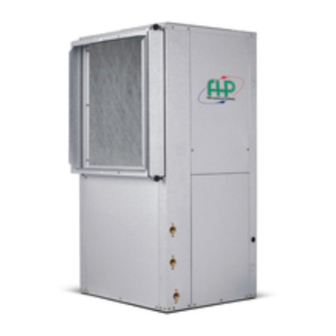
Summary of Contents for Bosch EP Series
- Page 1 EP Series EP007, EP009, EP012, EP015, EP018, EP024, EP030, EP036, EP042, EP048, EP060,EP070 Installation and Maintenance Manual...
-
Page 2: Table Of Contents
EP Series CONTENTS Maintenance..............24 Model Nomenclature............3 Unit Check-Out Sheet ............25 Customer Data............25 Initial Inspection..............4 Unit Nameplate Data..........25 Operating Conditions..........25 General Description............4 Auxiliary Heat ............25 Moving and Storage............5 troubleshooting .............. 26 Location................5 Standard Motor PSC INSTALLATION ..............5... -
Page 3: Model Nomenclature
EP Series Model Nomenclature | 3 MODEL NOMENCLATURE 8733953041 (2019/01) EP Series... -
Page 4: Initial Inspection
NOT use these units as a source of heating GENERAL DESCRIPTION or cooling during the construction process. EP Series Water-to-Air Heat Pumps provide the Doing so may affect the unit’s warranty. The best combination of performance and efficiency mechanical components and filters will available. -
Page 5: Moving And Storage
EP Series Moving and Storage | 5 INSTALLATION NOTE: 50° Minimum Entering Water MOUNTING VERTICALLY Temperature (EWT) for well water applications Vertical units up to six tons are available in left or with sufficient water flow to prevent freezing. right air return configurations. Vertical units... -
Page 6: Hanging Bracket Kit
6 | Hanging Bracket Kit EP Series 2. Mount 4 Brackets to unit corner post using the bolts provided in the kit as shown on Figure#6. NOTE: IF unit is located in a crawl space, the bottom of the unit MUST be at least 4” above... -
Page 7: Condensate Drain
EP Series CONDENSATE DRAIN | 7 CONDENSATE DRAIN DUCT SYSTEM If equipped with float style condensate Supply air duct and return air duct flanges are overflow switch, final adjustment must be shipped unfolded with unit. made in the field. A supply air outlet collar and return air duct flange... -
Page 8: Piping
8 | Piping EP Series The return air inlet to the heat pump must have at NOTE: Do not overtighten the connections. least one 90 degree turn away from the space return air grille. If air noise or excessive air flow are a problem, the... -
Page 9: Ecm Interface Board
EP Series Thermostat Connections | 9 THERMOSTAT CONNECTIONS Thermostat wiring is connected to the 10 pin screw type terminal block on the lower center portion of the ECM Interface Board. In addition to providing a connecting point for thermostat wiring,... - Page 10 10 | Thermostat Connections EP Series NOTE: Do not set the ADJ DIP switch to the EM (Red) Emergency Heat On (-) setting when electric heaters are installed. Doing so may cause the heaters to W1 (Red Auxiliary Heat On...
-
Page 11: Safety Devices And The Upm Controller
EP Series Safety Devices and the UPM Controller | 11 SAFETY DEVICES AND THE UPM • High pressure switch located in the refrigerant discharge line and wired across the HPC CONTROLLER terminals on the UPM • Low pressure switch located in the unit refrigerant suction line and wired across terminals LPC1 and LPC2 on the UPM. - Page 12 12 | Safety Devices and the UPM Controller EP Series • MALFUNCTION OUTPUT: Alarm output is UPM Board Factory Default Settings If pulse is Normally Open (NO) dry contact. selected the alarm output will be pulsed. The TEMP 26°F fault output will depend on the dip switch LOCKOUT setting for “ALARM”.
-
Page 13: Electronic Thermostat Installation
EP Series Electronic Thermostat Installation | 13 ELECTRONIC THERMOSTAT NOTE: If unit is employing a fresh water INSTALLATION system (no anti-freeze protection), it is Position the thermostat subbase against the wall extremely important to have the Freeze1 so that it is level and the thermostat wires R42 resistor set to 26°F in order to shut... -
Page 14: Upm Sequence Of Operation
14 | UPM SequenCE of Operation EP Series UPM SEQUENCE OF OPERATION START RESET ON R RESET ON Y1 = ON R = 24VAC POWER/ SWITCHES/SENSOR CLEAR FAULTS STATUS CHECK BLINK CODE ON STATUS LED COUNTER SOFT LOCKOUT V > 18VAC... -
Page 15: Electric Heater Package Option
For open loop systems, water quality is very Each EP Series model has a number of heater sizes important. Refer to Quality Table on page# 6 available. Refer to Figure #18 for heater package... -
Page 16: Water Quality Table
16 | water quality table EP Series WATER QUALITY TABLE POTENTIAL Water Characteristic Acceptable Value PROBLEM Copper Cupro-Nickel pH (Acidity/Alkalinity) Hardness (CaCO3, < 350 ppm < 350 ppm MgCO3) SCALING Ryznar Stability Index 6.0 - 7.5 6.0 - 7.5 Langelier Saturation Index -0.5 - +0.5... -
Page 17: Heat Recovery Package
EP Series Heat Recovery Package | 17 HEAT RECOVERY PACKAGE 3. Close cold water inlet valve to water heater tank. The Heat Recovery Package (HRP) is a factory 4. Drain tank by opening drain valve on the mounted option. It consists of a forced pumped... -
Page 18: Water Tank Refill
Hot gas reheat is an active dehumidification option elements and thermostats, the lower element available on the EP series that cools and should be turned down to 100° F, while the dehumidifies return air, and then reheats it back to upper element should be adjusted to 120°... -
Page 19: Sequence Of Operation
EP Series Sequence of Operation | 19 SEQUENCE OF OPERATION APPLICATION CONSIDERATIONS Cooling Mode Well Water Systems Energizing the “O” terminal energizes the unit reversing valve in the cooling mode. The fan motor NOTE: In well water applications a slow starts when the “G”... -
Page 20: Installation Of Pressure Regulating Valves
20 | Installation of Pressure Regulating Valves EP Series Figure # 20 [1] Line voltage disconnect (unit) A refrigerant tap is provided in the refrigerant line located between the reversing valve and the water- [2] Flex duct Connection to-refrigerant heat exchanger for proper [3] Low voltage control connection monitoring of the refrigerant pressures. - Page 21 EP Series Cooling Tower/Boiler Systems | 21 When utilizing open cooling towers, chemical installed in the supply and return lines for unit water treatment is mandatory to ensure the water isolation and unit water flow balancing. Pressure/ is free from corrosive elements. A secondary heat...
-
Page 22: Geothermal (Earth-Coupled) Systems
22 | Cooling Tower/Boiler Systems EP Series Geothermal (Earth-Coupled) Systems installation easy. Anti-freeze solutions are utilized when low evaporating conditions are expected to Closed loop and pond applications require occur. Refer to the GLP installation manuals for specialized design knowledge. No attempt at these more specific instructions. -
Page 23: System Checkout
EP Series System Checkout | 23 SYSTEM CHECKOUT UNIT START-UP After completing the installation, and before 1. Set the thermostat to the highest setting. energizing the unit, the following system checks 2. Set the thermostat system switch to “COOL”, should be made: and the fan switch to the “AUTO”... -
Page 24: Maintenance
24 | Maintenance EP Series MAINTENANCE 1. Filter changes or cleaning are required at regular intervals. The time period between filter changes will depend upon type of environment the equipment is used in. In a single family home, that is not under construction, changing or cleaning the filter every 60 days is sufficient. -
Page 25: Unit Check-Out Sheet
EP Series Unit Check-Out Sheet | 25 UNIT CHECK-OUT SHEET Customer Data Customer Name _____________________________________________ Date ___________________________________ Address ______________________________________________________ _______________________________________________________________ Phone _______________________________________________________ Unit Number ___________________________ Unit Nameplate Data Unit Make _________________________________________ Model Number ____________________________________ Serial Number ____________________________________ Refrigerant Charge (oz) __________________________... -
Page 26: Troubleshooting
26 | Troubleshooting EP Series TROUBLESHOOTING UPM Board LED Indications NOTE: Troubleshooting Information Indication Solution column may reflect a possible Color Blinks Description fault that may be one of, or a GREEN Solid 18-30 VAC Power is present combination of causes and solutions. - Page 27 EP Series Troubleshooting | 27 Unit Troubleshooting Problem Possible Cause Checks and Correction UNIT OFF ON Discharge In “COOLING” mode: Lack of or inadequate water flow. Entering water HIGH PRESSURE pressure too high temperature is too warm. Scaled or plugged condenser. In “HEATING”...
- Page 28 28 | Troubleshooting EP Series HRP Troubleshooting Problem Possible Cause Checks and Corrections NO FLOW No Power Check power supply LOW FLOW On/Off Switch Position Set switch to “ON” position Compressor Contactor Engage heat pump contactor Broken or loose wires...
-
Page 29: Standard Motor Psc
EP Series Standard Motor-PSC | 29 STANDARD MOTOR-PSC For 007-012, Constant torque for 015-070 Available External Static Pressure (inches of Water) Model Motor Speed High EP007 Medium High EP009 Medium High EP012 Medium High EP015 Medium High EP018 Medium High... -
Page 30: Constant Cfm Motors
30 | Standard Motor-PSC EP Series Available External Static Pressure (inches of Water) Model Motor Speed High 1645 1635 1610 1585 1560 1535 1510 1485 1460 1430 EP042 Medium 1455 1425 1400 1375 1345 1320 1290 1260 1225 1190 1220... - Page 31 EP Series Standard Motor-PSC | 31 Available External Static Pressure (inches of Water) Model Motor Speed 1150 1150 1150 1150 1150 1150 1150 1150 1150 EP030 Normal 1000 1000 1000 1000 1000 1000 1000 1000 1000 1380 1380 1380 1380...
-
Page 32: Water Side Pressure Drop
32 | Water Side Pressure drop EP Series WATER SIDE PRESSURE DROP Model Water Flow Rate Water Side Pressure Water Side Pressure Drop (GPM) Drop (PSI) (ft of H2O) EP007 10.1 EP009 3.25 EP012 10.2 EP015 EP018 10.4 16.7 EP024 11.6... -
Page 33: Air Temperature Rise/Fall
EP Series Air Temperature Rise/Fall | 33 AIR TEMPERATURE RISE/FALL Entering COOLING HEATING Fluid ° ° ° ° ° Temp Entering Air Temp F Air Temp Drop Entering Air Temp Air Temp Rise 15.9-23.5 13.5-22.9 14.8-22.4 75/63 20.6-25.0 18.5-26.7 80/67 21.6-25.6... -
Page 34: Refrigerant Pressure Ranges
34 | Refrigerant Pressure ranges EP Series REFRIGERANT PRESSURE RANGES COOLING HEATING Enteri Entering Air Temp (Dry Bulb) Entering Air Temp (Dry Bulb) Fluid ° ° ° ° ° Fluid ° Temp Suction Discharge Suction Discharge Suction Discharge Suction Discharge... -
Page 35: Unit Dimensions
EP Series Vertical dimensions | 35 VERTICAL DIMENSIONS 8733953041 (2019/01) EP Series... -
Page 36: Horizontal Dimensions
36 | Horizontal Dimensions EP Series HORIZONTAL DIMENSIONS 8733953041 (2019/01) Subject to change without prior notice EP Series... -
Page 37: Wiring Diagrams
EP Series Wiring Diagrams | 37 WIRING DIAGRAMS Figure # 23 FOR REFERENCE ONLY Actual unit wiring may vary from this example. Always refer to the wiring diagram attached to the unit. 8733953041 (2019/01) EP Series... - Page 38 38 | Wiring Diagrams EP Series Figure # 24 FOR REFERENCE ONLY Actual unit wiring may vary from this example. Always refer to the wiring diagram attached to the unit. 8733953041 (2019/01) Subject to change without prior notice EP Series...
- Page 39 EP Series Wiring Diagrams | 39 Figure # 25 FOR REFERENCE ONLY Actual unit wiring may vary from this example. Always refer to the wiring diagram attached to the unit. 8733953041 (2019/01) EP Series...
- Page 40 40 | Wiring Diagrams EP Series Figure # 26 FOR REFERENCE ONLY Actual unit wiring may vary from this example. Always refer to the wiring diagram attached to the unit. 8733953041 (2019/01) Subject to change without prior notice EP Series...
- Page 41 EP Series Wiring Diagrams | 41 Figure # 27 FOR REFERENCE ONLY Actual unit wiring may vary from this example. Always refer to the wiring diagram attached to the unit. 8733953041 (2019/01) EP Series...
- Page 42 42 | Wiring Diagrams EP Series Figure # 28 FOR REFERENCE ONLY Actual unit wiring may vary from this example. Always refer to the wiring diagram attached to the unit. 8733953041 (2019/01) Subject to change without prior notice EP Series...
-
Page 43: Notes
EP Series Notes | 43 NOTES 8733953041 (2019/01) EP Series... - Page 44 Bosch Thermotechnology Corp 555 NW 65th Court Ft.Lauderdale, FL 33309 Phone: 954-776-5471 | Fax: 954-776-5529 www.bosch-climate-us Revised: 01/2015...
Need help?
Do you have a question about the EP Series and is the answer not in the manual?
Questions and answers