Table of Contents
Advertisement
Quick Links
Advertisement
Table of Contents

Subscribe to Our Youtube Channel
Related Manuals for DiaSys mini+


Summary of Contents for DiaSys mini+
- Page 1 Operator Manual For the Water purifier Operator’s manual version: 2021.06...
-
Page 2: Table Of Contents
ONTENT Safety information ............................3 Warning labels ............................. 3 Safety instructions ..........................3 Introduction to the system .......................... 4 Introduction ............................4 Technical specifications ........................4 Overview of the system (front view) ....................5 Overview of the system (back view) ....................6 General description .......................... - Page 3 Maintenance procedures ........................26 Flow measurement procedure ....................26 Understanding conductivity values ................... 27 Change of SEDIMENT FILTER 5 µm .................... 29 Change of ACTIVE CARBON BLOCK FILTER ................30 Change of the 2 RESIN CARTRIDGES ..................31 Change of POST TREATMENT CARTRIDGE ................. 33 Change of the REVERSE OSMOSIS MEMBRANE ................
-
Page 4: Safety Information
AFETY INFORMATION Read the safety information before installing the water purifier 2.1 W ARNING LABELS Before reading the manual, please get familiarized with the following icons used in this manual. Electric Shock Warnings Specific Information without security link 2.2 S AFETY INSTRUCTIONS To ensure the product SECURITY and RELIABILITY, all repairing must be realized with spare parts available with our after-sales service. -
Page 5: Introduction To The System
NTRODUCTION TO THE SYSTEM 3.1 I NTRODUCTION The water purifier system «O mini+» produces water of Class 2 as defined in ISO 3696 standard, which is indented to be used by clinical analyzers. The principle of purification uses two technologies: the REVERSE OSMOSIS, which is currently the most effective membranous separation process, the demineralization by ion exchange resin. -
Page 6: Overview Of The System (Front View)
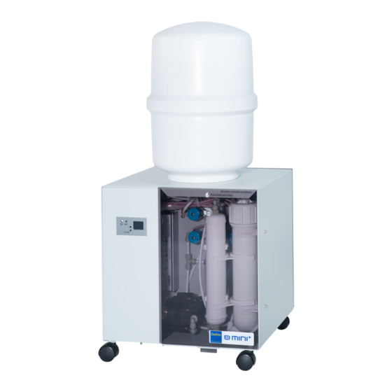
3.3 O VERVIEW OF THE SYSTEM FRONT VIEW Pressurized water tank Controller Reverse osmosis membrane inverse Post treatment cartridge Booster pumper Operator’s manual version: 2021.06... -
Page 7: Overview Of The System (Back View)
3.4 O VERVIEW OF THE SYSTEM BACK VIEW 5µm sediment filter Active carbon Resin filter block filter 3.5 G ENERAL DESCRIPTION The "O mini+" water purifier includes a set of prefiltration cartridges for filtering the inlet water: 5µm sediment filter + carbon block filter. After this stage, the water is injected via a booster pump into one reverse osmosis membrane. -
Page 8: Controller Description
3.6 C ONTROLLER DESCRIPTION Main display The conductivity of the produced water is displayed continuously on the main screen. Menu access (press 2 seconds) Conductivity of produced water Unity System status Flush(wash) button Detailed information button Operator’s manual version: 2021.06... -
Page 9: Menu Display
Menu display The settings menu is displayed after pressing 2 seconds with a tool on the SET button. Menu’s title Selection (press 2 seconds) Different choices Moving in the menu Detailed information display From the main menu, when pressing shortly on the ‘+’ button, the values from various sensors are displayed momentarily. -
Page 10: Phases De Fonctionnement
Phases de fonctionnement The conductivity of the produced water can be different from 1.0. US/CM The remaining time to finish the purge process is displayed (seconds). The water purifier is rinsing the membrane after start- up, periodically (by default each 6 hours), or when pressing shortly on the ‘FLUSH’... -
Page 11: Settings Menu
Settings menu The settings menu is accessible by pressing with a tool on the SET button for 2 seconds. SETTINGS The available sub-menus are: CALIBRATION TELEMETRY • Calibration of the conductivity electrodes CONTRAST • Telemetry management SERVICE • Screen contrast adjustment •... -
Page 12: General Comments On The Calibration Of The Conductivity Electrodes
General comments on the calibration of the conductivity electrodes The calibration process is not forced by the system. However it is possible to adjust the displayed value on the controller’s screen if it is different from the value measured with an external calibrated conductivity meter. - Page 13 3.6.7.3 Use of the adjustment screen The calibration of the integrated conductivity electrodes is processed with the inner water. In parallel, the conductivity of this water has to be measured with an external conductivity meter which needs to be previously calibrated. xxxxxx POINT x CONDUCTIVITY •...
- Page 14 3.6.7.4 Calibration curve with one point As the electrodes are not accessible by the user, they are able to measure only the conductivity of the water crossing the system. • Point of calibration: grey vertical line. • The calibration curve goes from 0 to the point of calibration. •...
- Page 15 3.6.7.5 Calibration curve with 2 points As the electrodes are not accessible by the user, they are able to measure only the conductivity of the water crossing the system. • Points of calibration: where are the 2 grey vertical lines. •...
-
Page 16: Calibration Of The Production Conductivity Electrode
Calibration of the production conductivity electrode The calibration of the production conductivity electrode is made by taking water directly from the output of the purified water. The points of calibration must have conductivity values strictly under 10µS/cm. 3.6.8.1 To define a 1st point of calibration This is the initial case, before any saving of calibration point. -
Page 17: Calibration Of The Membrane Conductivity Electrode
Calibration of the membrane conductivity electrode 3.6.9.1 How to take water after the membrane 1. Switch off the water purifier 2. Close the valve on top of the pressurized water tank 3. Open the valve « purified water output » during 30 seconds then close it again 4. - Page 18 3.6.9.4 To define a 2nd point of calibration This is the initial case, before any saving of calibration point. CALIBRATION PROD CONDUCTIVITY MEMBRANE CONDUCTIVITY SELECT:PRESS SET 2 SEC 3.6.9.5 To delete the 2nd point of calibration It is possible to come back to one only point of calibration by deleting the 2 point of calibration.
-
Page 19: Telemetry Management
Telemetry management The telemetry feature allows to monitor and to record the measurements of conductivity, pressure, temperature, and status of the water purifier, on a PC connected by a USB cable. When in the activation screen, to active/unactivate the telemetry function, press with a tool for 2 seconds on the ‘SET’... -
Page 20: Installing The Water Purifier
NSTALLING THE WATER PURIFIER 4.1 I NSTALLATIONS ONDITIONS Water inlet (2 to 6 bars) equipped with a turn hand valve and a male exit tap of 1/2" delivered with the packing list (male connector 1/4" quick fit / 1/2" NPTF or water inlet valve 1/2" male/female). ... -
Page 21: Installation Of The Water Purifier Membrane
4.3 I NSTALLATION OF THE WATER PURIFIER MEMBRANE 1. Remove the membrane holder out of its two plastic stirrups. (Figure 1) 2. Disconnect the water inlet pipe from the membrane holder by disconnecting the quick fit coupling. (Figure 2) 3. Unscrew (by turning to the right) the high streaked part ("big cap") of the membrane holder. 4. -
Page 22: Water Purifier Start-Up
WATER PURIFIER START 1. Connect all the tubings to the water purifier. 2. Check all hydraulic connections. 3. Close the storage tank valve. 4. Open the water purifier exit hand valve. 5. Open the tap water supply valve. 6. Connect the power supply cable and switch ON the water purifier. 7. -
Page 23: User Maintenance
SER MAINTENANCE 6.1 M AINTENANCE CALENDAR In order to maintain an optimal functioning of the water purifier, it is necessary to check regularly the water purifier and to perform the first level maintenance. These actions must be executed by the user. The following table lists the actions and their frequency. Calendar Frequency Operation... -
Page 24: System Errors
6.2 S YSTEM ERRORS When there is a malfunction, the water purifier stops, the ‘EC’LED blinks in red color and the controller displays the potential causes of error with a code. Call the service. 6.3 I NTEGRATED CONDUCTIVITY ELECTRODE ERROR When there is an issue with the integrated conductivity electrodes, the water purifier continues to operate, but does not report any more the conductivity measure by the faulty electrode. -
Page 25: Consumables
6.4 C ONSUMABLES Filter kit « O mini+ » (ref. 950039) The O mini+ Filters kit contains the following consumables: The 5 µm sediments cartridge (10") +1 seal Pre-treatment The active carbon block cartridge ( 10") + 1 seal Post-treatment The 1 µm post-treatment cartridge (10") 5µm sediment filter Active carbon... -
Page 26: O Mini+" Membrane Kit (Ref. 950023)
«O mini+» MEMBRANE KIT (ref. 950023) Reverse osmosis membrane Flow restrictor The reverse osmosis membrane and the flow restrictor must be replaced when the flow of purified water outlet is significantly low despite of a recent replacement of pre-treatment filters or/and an important increase in the frequency of the ions exchangers resins bottle replacement. -
Page 27: Maintenance Procedures
6.5 M AINTENANCE PROCEDURES Flow measurement procedure 6.5.1.1 General points The flow measurement is interesting to check the filters and reverse osmosis membrane plugging state. The osmosis membrane flow is function of the supply water temperature. We generally allow a flow drop of 3 % per Celsius degree in a range from 10 to 25 °C. This flow measurement must be compared to the water purifier theoretical nominal value with a fixed temperature, which is 25 °C: Note: this theoretical flow rate represents the production at a "tank outlet"... -
Page 28: Understanding Conductivity Values
Understanding conductivity values 6.5.2.1 General information The global quantity of dissolved solids in water can be measured by the CONDUCTIVITY (expressed in microSiemens per centimeter (µS / cm). 6.5.2.2 Production conductivity « output of water purifier » The conductivity of the produced water is below 1µS/cm The conductivity indicator... - Page 29 6.5.2.3 Conductivity of « after membrane» It is possible to check the conductivity after the membrane on the « DETAILS » screen. Conductivity of water after the membrane (µS/cm) Is the conductivity « after membrane » above 25 µS/cm after running about 1 liter of production water? , THEN change: o the membrane (see paragraph 6.5.7)
-
Page 30: Change Of Sediment Filter 5 Μm
Change of SEDIMENT FILTER 5 µm 1. Close the tap water hand valve. 2. Close the storage tank hand valve. 3. Open the water purifier exit hand valve to reduce the water pressure inside the water purifier; on the controller screen is displayed «NO FEED». Keep the water purifier exit hand valve open. 4. -
Page 31: Change Of Active Carbon Block Filter
Change of ACTIVE CARBON BLOCK FILTER 1. Close the tap water hand valve. 2. Close the storage tank hand valve. 3. Open the water purifier exit hand valve to reduce the water pressure inside the water purifier; on the controller screen is displayed «NO FEED». Keep the water purifier exit hand valve open. 4. -
Page 32: Change Of The 2 Resin Cartridges
Change of the 2 RESIN CARTRIDGES 1. Close the tap water hand valve. 2. Close the storage tank hand valve. 3. Open the water purifier exit hand valve to reduce the water pressure inside the water purifier; on the controller screen is displayed «NO FEED». Keep the water purifier exit hand valve open. 4. - Page 33 9. For changing the 0.25L in-line resin cartridge, move out the cartridge from the 2 stirrups and disconnect the 2 connectors. 0.25L inline resin cartridge Move out the 0.25L resin cartridge from its 2 stirrups and then disconnect the 2 connectors 10.
-
Page 34: Change Of Post Treatment Cartridge
Change of POST TREATMENT CARTRIDGE 1. Close the tap water hand valve. 2. Close the storage tank hand valve. 3. Open the water purifier exit hand valve to reduce the water pressure inside the water purifier; on the controller screen is displayed «NO FEED». Keep the water purifier exit hand valve open. 4. -
Page 35: Change Of The Reverse Osmosis Membrane
Change of the REVERSE OSMOSIS MEMBRANE 1. Close the tap water hand valve. 2. Close the storage tank hand valve. 3. Open the water purifier exit hand valve to reduce the water pressure inside the water purifier; on the controller screen is displayed «NO FEED». Keep the water purifier exit hand valve open. 4. -
Page 36: Change Of Flow Restrictor
Change of FLOW RESTRICTOR 1. Close the tap water hand valve. 2. Close the storage tank hand valve. 3. Open the water purifier exit hand valve to reduce the water pressure inside the water purifier; on the controller screen is displayed «NO FEED». Keep the water purifier exit hand valve open. 4. -
Page 37: Packing List
ACKING LIST Picture picture Item Item water purifier “O mini+” 12 LITERS PRESSURIZED TANK reference 951200 Reference 950228 RO MEMBRANE 75 GPD SPANER FOR 10" FILTER HOLDER POLYETHYLENE TUBE 1/4" – 10 Meters DRAIN CLAMP Reference 950515 WATER INLET VALVE 1/2" WRENCH FOR MEMBRANE (mâle/female) HAND VALVE 1/4"... -
Page 38: Service
SERVICE The information in this chapter are reserved exclusively to service technicians. 8.1 ‘SERVICE’ MENU The ‘SERVICE’ menu, reserved to the service technicians, allows operations with risks of degradation and malfunction of the water purifier: Change of delays: flush duration; purge duration; time between 2 automatic flushes Firmware update Switch ON demonstration mode (screens displayed without checking sensors) Display firmware serial number... -
Page 39: Timings Change
Timings change These operations are reserved to service technicians. 8.1.1.1 Change flush duration TIME SETTINGS FW UPDATE DEMO MODE ABOUT SELECT:PRESS SET 2 SEC Press on ‘+’ or ‘-‘ to adjust the value. Validate by pressing with a tool for 2 seconds on the ‘SET’ button. 8.1.1.2 Change purge duration TIME SETTINGS... -
Page 40: Firmware Update
FW UPDATE CONFIRM DEMO MODE ABOUT SELECT:PRESS SET 2 SEC DEMO ON SELECT:PRESS SET 2 SEC Firmware version display COPYRIGHT SERVICE DIASYS TECHNOLOGIES TIME SETTINGS FRANCE FW UPDATE FIRMWARE: DEMO MODE X3110820C ABOUT ABOUT SELECT:PRESS SET 2 SEC Operator’s manual version: 2021.06... -
Page 41: Management Of The Errors Reported By The Controller
8.2 M ANAGEMENT OF THE ERRORS REPORTED BY THE CONTROLLER Functional errors In case of malfunction, the controller displays certain causes of error, and one error code. The error code after # contains 3 characters : # X Y Z Short circuit Cut circuit Pressure error... - Page 42 8.2.1.1 Short circuit detection Binary code CAUSE SUGGESTED ACTION XXX1 Purge valve in short circuit Change the pruge valve XX1X Production valve in short circuit Change the production valve X1XX Pump and inlet valve in short circuit Change the pump and the inlet valve 1XXX Flush valve in short circuit Change the flush valve...
-
Page 43: Errors With Integrated Conductivty Electrodes
Errors with integrated conductivty electrodes In case of problem with one integrated conductivity electrode, the controller continues to run, does not display the corresponding conductivity, but instead one error code on the « DETAILS » screen. Problem with the conductivity electrode Error code CAUSE... -
Page 44: Spare Parts
8.4 S PARE PARTS Membrane housing ref. 950207 Controller Ref. 950547 Power supply ref. 950577 Booster Pump ref. 950519 Electromagnetic Production conductivity sensor ref. 951107 valves ref. 950576 Membrane conductivity sensor ref. 951107 Operator’s manual version: 2021.06... - Page 45 Inlet pressure sensor ref. 951204 USB Communication board ref. 950558 Membrane pressure sensor ref. 951204 10" white filter housing ref. 950238 10 " transparent filter housing ref. 950209 Operator’s manual version: 2021.06...
-
Page 46: Flow Path Diagram
8.5 F LOW PATH DIAGRAM The hydraulic wiring is in 1/4 "tubing To drain Flow restrictor Inlet pressure Booster Hand sensor Pump valve Flush solenoid valve Reverse osmosis Purge membrane solenoid Inlet Water valve Solenoid Check valve inlet valve 2 voies Production solenoid valve Membrane... - Page 47 DiaSys Technologies 1682, rue de la Valsière Cap Gamma – Parc Euromédecine II 34790 GRABELS Tél. : 33 (0)4 11 95 03 40 Fax : 33 (0)4 11 95 03 50 Internet : http://www.diasys-diagnostics.com Email : info@diasys-technologies.com Operator’s manual version: 2021.06...
Need help?
Do you have a question about the mini+ and is the answer not in the manual?
Questions and answers