Table of Contents
Advertisement
Quick Links
Advertisement
Table of Contents

Subscribe to Our Youtube Channel
Related Manuals for DiaSys O MINI


Summary of Contents for DiaSys O MINI
- Page 1 Operator Manual Water purifier Omini operator’s manual version :19.04.17...
-
Page 2: Table Of Contents
ONTENT Safety Informations ......................... 2 Warning labels ......................... 2 Safety instructions ........................2 Introduction to the system ......................3 Introduction ..........................3 Overview of the system (front view) ..................3 Overview of the system (back view) ..................4 General description ......................... 4 Description of the control unit .................... -
Page 3: Safety Informations
AFETY NFORMATIONS Read the safety information before installing the water purifier 2.1 W ARNING LABELS Before reading the manual, please get familiarized with the following icons used in this manual. Electric Shock Warnings 2.2 S AFETY INSTRUCTIONS To ensure the product SECURITY and RELIABILITY, all repairing must be realized with spare parts available with our after-sales service. -
Page 4: Introduction To The System
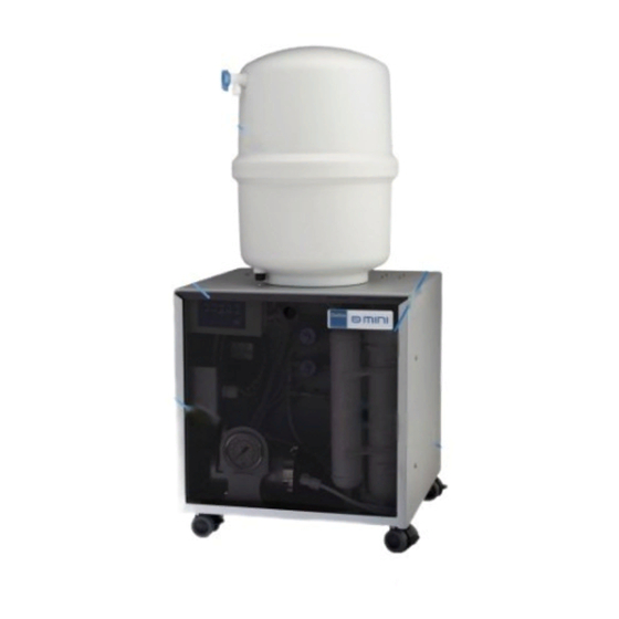
NTRODUCTION TO THE SYSTEM 3.1 I NTRODUCTION The DiaSys water purifier « O MINI » is a purified water production system allowing two water treatment leading-edge technologies: The BI-REVERSE OSMOSIS, which is currently the most effective and elaborated - membranous separation process, The demineralization principle by IONS EXCHANGERS RESINS. -
Page 5: Overview Of The System (Back View)
3.4 G ENERAL DESCRIPTION The "o mini" osmosis system is a water treatment system that includes a series of prefiltration cartridges for the network water: Sediment filter 5 μm + Block carbon filter. Once this water is treated, it is then injected via a booster pump into the reverse osmosis membrane. -
Page 6: Description Of The Control Unit
3.5 D ESCRIPTION OF THE CONTROL UNIT Terms meaning : PUMP : PUMP FLUSH : RINSING SOURCE : WATER SUPPLY FULL : FULL TANK POWER : UNDER TENSION MANUAL : MANUAL RINSING PUMP indicator turned on Pump functioning: means the water purifier is either producing or rinsing. -
Page 7: Technical Specifications
ECHNICAL SPECIFICATIONS Power supply voltage 230 volts ~ / 50 Hz. Production flow at 25 ° C 15 liters / hour Production flow at 10 ° C 9 liters / hour Resin type Resin with mixed beds Resins volume 0.75 liters Maximum supply water temperature 38 °C Maximum hardness without protection... -
Page 8: Installing The Water Purifier
NSTALLING THE WATER PURIFIER 5.1 I NSTALLATIONS ONDITIONS Water inlet (2 to 5 bars) equipped with a turn hand valve or a male exit tap of 15/21 or 20/27. Protected electric input (230 V ~, 50 Hz + EARTH). ... -
Page 9: Installation Of The Water Purifier Membrane
5.3 I NSTALLATION OF THE WATER PURIFIER MEMBRANE 1. Remove the membrane holder out of its two plastic stirrups . (Figure 1) 2. Disconnect the water inlet pipe from the membrane holder by disconnecting the quick fit coupling. (Figure 2) 3. -
Page 10: System Start Up
YSTEM START UP 1. Connect the water purifier hydraulically then electrically. 2. Check all hydraulic connections. 3. Close the storage tank valve. 4. Open the water purifier exit hand valve. 5. Open the city water supply valve. 6. Electrically switch on the water purifier. 7. -
Page 11: Maintenance And Service
AINTENANCE AND SERVICE 7.1 M AINTENANCE CALENDAR In order to insure an optimal functioning of the water purifier, it is necessary to realize a certain number of controls and maintenance of first level. These actions must be realized by the customer. The following board gives the controls to make and the actions of maintenance to realize, their frequency and the operator. -
Page 12: Troubleshooting
7.2 T ROUBLESHOOTING PROBLEMS POTENTIAL CAUSES SUGGESTED ACTION Verify the power supply No power supply wires ; switch power ON Power light OFF Power supply fuse is broken Check and replace the fuse • Power light ON The inlet tap water supply is closed Improve water supply •... -
Page 13: Consumables
7.3 C ONSUMABLES OMINI Filters kit (ref. 950039) The OMini Filters kit contains the following consumables: The 5 µm sediments cartridge (10") Pre-treatment The active carbon block cartridge ( 10") Post-treatment The 1 micron post traitement cartridge (10") Filter for Active carbon sediments 5 μm... -
Page 14: Omini Membrane Kit (Ref. 950023)
OMini Membrane kit (ref. 950023) Flow Restrictor Reverse osmosis membrane The reverse osmosis membrane and the flow restrictor must be replaced when the flow of purified water outlet is significantly low despite of a recent replacement of pre-treatment filters or/and an important increase in the frequency of the ions exchangers resins bottle replacement . -
Page 15: Maintenance Procedures
7.4 M AINTENANCE PROCEDURES Flow measurement procedure 7.4.1.1 General points The flow measurement is interesting to check the filters and reverse osmosis membrane plugging state. The osmosis membrane flow is function of the supply water temperature. We generally allow a flow drop of 3 % per Celsius degree in a range from 10 to 25 °C. This flow measurement must be compared to the water purifier theoretical nominal value with a fixed temperature, which is 25 °C: Note: this theoretical flow rate represents the production at a "tank outlet"... -
Page 16: Conductivity Measurement Procedure
Conductivity measurement procedure 7.4.2.1 General points The global quantity of dissolved solids in water can be measured by the CONDUCTIVITY (expressed in microsiemens per centimeter (µS / cm). The conductivity measurement allows estimating the demineralization quality. The relation between the TDS (total dissolved solids = total mineralization) and the conductivity is: 1 µS / cm ≈... -
Page 17: Change Of Sediment Filter 5 Μm
Change of SEDIMENT FILTER 5 µm 1. Close the tap water hand valve. 2. Close the storage tank hand valve. 3. Open the water purifier exit hand valve to depressurize the network; the indicator « SOURCE » of the electronic unit lights. Leave the water purifier exit hand valve open. Turn off the water purifier (switch in position «... -
Page 18: Change Of Active Carbon Block Filter
Change of ACTIVE CARBON BLOCK FILTER 1. Close the tap water hand valve. 2. Close the storage tank hand valve. 3. Open the water purifier exit hand valve to depressurize the network; the indicator « SOURCE » of the electronic unit lights. Leave the water purifier exit hand valve. -
Page 19: Change Of Resin Cartridge
Change of RESIN CARTRIDGE 1. Close the tap water hand valve. 2. Close the storage tank hand valve. 3. Open the water purifier exit hand valve to depressurize the network; the indicator SOURCE » of the electronic unit lights. Leave the water purifier exit hand valve. -
Page 20: Change Of The Post Treatment Cartridge: Sediment 1 Μm
Change of the POST TREATMENT CARTRIDGE: SEDIMENT 1 µm 1. Close the tap water hand valve. 2. Close the storage tank hand valve. 3. Open the water purifier exit hand valve to depressurize the network; the indicator « SOURCE » of the electronic unit lights. Leave the water purifier exit hand valve. Turn off the water purifier (switch in position «... -
Page 21: Change Of The Reverse Osmosis Membrane
Change of the REVERSE OSMOSIS MEMBRANE 1. Close the tap water hand valve. 2. Close the storage tank hand valve. 3. Open the water purifier exit hand valve to depressurize the network; the indicator « SOURCE » of the electronic unit lights. Leave the water purifier exit hand valve open. 4. -
Page 22: Change Of Flow Restrictor
Change of FLOW RESTRICTOR 1. Close the tap water hand valve. 2. Close the storage tank hand valve. 3. Open the water purifier exit hand valve to depressurize the network; the indicator « SOURCE » of the electronic unit lights. Leave the water purifier exit hand valve open. Turn off the water purifier (switch in position «... -
Page 23: Spare Parts
7.5 S PARE PARTS Solenoid valve ref. 950277 Electronic controller ref. 950227 membrane housing ref. 950207 Post-treatment Sediment filter Booster pump Manometer 0-10 BARS ref. 950232 ref. 950231 Low pressure Pressostat ref. 950232 High pressure Pressostat ref. 950231 Omini operator’s manual version :19.04.17... - Page 24 Filter holder 10 " transparent body Filter holder 10" ref. 950209 white body ref. 950238 Omini operator’s manual version :19.04.17...
-
Page 25: Flow Path Diagram
LOW PATH DIAGRAM To drain Flow restrictor Pump valve Reverse Osmosis Membrane Double water check valve inlet Pressurized storage tank (osmosed water) Valve Purified water exit Omini operator’s manual version :19.04.17... -
Page 26: Packing List
ACKING LIST Picture picture Item Item water purifier OMINI 12 LITERS PRESSURIZED TANK reference 950006 Reference 950228 RO MEMBRANE 75 SPANER FOR 10" FILTER HOLDER PEN CONDUCTIVITY HAND VALVE 1/4" METER Reference 950330 quantity :2 TEE UNION 1/4" TWO WAY DIVIDER 1/4" Reference 950094 Reference 950091 quantity :2 MALE CONNECTOR... - Page 27 1682, rue de la Valsière Cap Gamma – Parc Euromédecine II 34790 GRABELS Tél. : 33 (0)4 11 95 03 40 Fax : 33 (0)4 11 95 03 50 Internet : http://www.diasys-diagnostics.com Email : info@diasys-technologies.com Omini operator’s manual version :19.04.17...
Need help?
Do you have a question about the O MINI and is the answer not in the manual?
Questions and answers