
Related Manuals for PEMTECH Ultra 1000


Summary of Contents for PEMTECH Ultra 1000
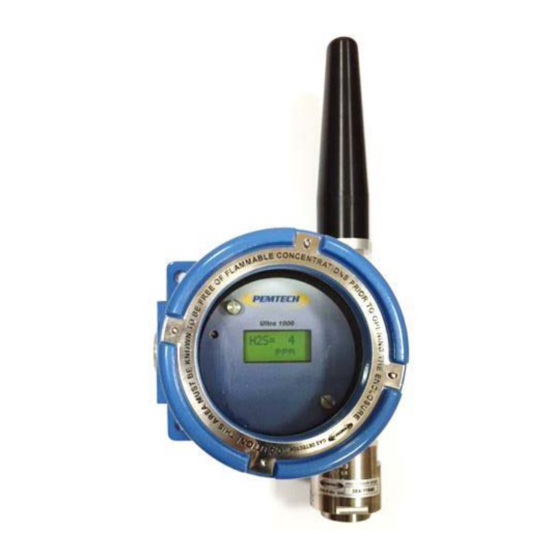
- Page 1 Gas Detection Technology Ultra 1000 Wireless Gas Detector S & Other Toxics Operator’s Manual March 2015 Rev 2.2 Pem-Tech, Inc. Houston, Texas U.S.A. www.pem-tech.com...
- Page 2 NOTICE PEM-TECH INCORPORATED SHALL NOT BE LIABLE FOR TECHNICAL OR EDITORIAL ERRORS OR OMISSIONS MADE HEREIN, NOR FOR INCIDENTAL OR CONSEQUENTIAL DAMAGES RESULTING FROM THE FURNISHING, PERFORMANCE, OR USE OF THIS MATERIAL LIMITED WARRANTY Pem-Tech, Incorporated warrants all the equipment to be free from defects in workmanship and material. The products will operate in conformance with the published specifications when subjected to intended and proper usage for the period of one (1) year from the date of shipment.
- Page 3 SERVICE POLICY Pem-Tech has service facility at the factory. For all the repairs contact at our toll free number 1-800- 379-3894 or visit our website www.pem-tech.com For all repairs call us for a Return Material Authorization number (RMA). Inform us briefly the nature of the problem and obtain shipping address.
-
Page 4: Table Of Contents
TABLE OF CONTENTS Page # Specifications Overview Setting up Wireless Detectors Installing Detectors Power up Wireless Detectors Programming Sensor Address and Zone ID 4 Sensor Calibration 4.1 Adjusting Sensor Zero Only 4.2 Calibration Errors and Remedies 4.3 Calibration Flow Chart 5 Maintenance Replacing Lithium batteries Replacing Sensor head assembly... -
Page 5: Specifications
1.0 Specifications Sensor Specifications Sensor Range Response Time 0 – 100 ppm T90 < 30 sec 0 – 100 ppm T90 < 30 sec 0 – 50 ppm T90 < 50 sec 0 – 25 % T90 < 15 sec 0 –... -
Page 6: Overview
2.0 Overview Ultra1000 series wireless sensor is used for air quality monitoring. The sensor detects toxic gas or vapors in air and sends the signal to a Gas Monitor / Controller over a wireless data network. A complete data packet is transmitted to the wireless controller (or receiver). The data packet includes the current gas reading, sensor diagnostic data and battery voltage. -
Page 7: Setting Up Wireless Detectors
3.0 Setting up Wireless Detectors 3.1 Installing Detector Mount the detector to a flat surface or on struts. When mounting to a wall or flat surface use proper hardware to have at least 2-3 inches between the wall and the sensor enclosure. - Page 8 To shut down the detectors when not in use place and hold the magnet on top of the enclosure just like in power On mode for few seconds. Detector will display shut down message and will shut down the power from the batteries in 5 seconds. Magnet tool to activate Internal switch Figure 1.
-
Page 9: Programming Sensor Address And Zone Id
3.3 Programming Sensor Address & Zone/Network ID Initially the sensor must be assigned with a sensor Address (Unit ID) and Network / Zone ID. The sensor address and zone id needs to be programmed only once. The data is retained in a non- volatile memory and is not lost when the detector is powered down. - Page 10 Magnet tool to activate Internal switch Edit Config Mode. Setting Unit Address & Zone ID Figure 2. Note: Network / Zone ID should be set to 0 unless multiple Controllers / Gateways are used within the transmitting range of each other. The default Zone ID is 0 for all the gateways, controllers and sensors shipped from the factory.
-
Page 11: Sensor Calibration
8. To Exit simply hold the magnet at 4 o’clock position and the sensor will return to normal operation. The sensor may re-boot if the zone id is modified. The new zone ID will be retained in the non-volatile memory and will be recalled upon next power up. Caution The default Zone ID is 0 set at the factory for all the detectors and the controller. - Page 12 Place and hold the magnet until display indicates the “Calib Sensor” . Move the magnet away from the cover. Magnet tool to activate Internal switch Figure 3. Activating internal magnetic switch for sensor calibration mode While the Calib Sensor message is being displayed the sensor is making its initial adjustments.
-
Page 13: Adjusting Sensor Zero Only
clear. Do not remove the calibration gas while the sensor is adjusting. Remove the gas only when Calibration OK message is displayed. The sensor calibration has been successfully completed and “Calibrat OK” message is displayed for few seconds. The sensor will return to normal operation once all the calibration gas is cleared out of the sensor head and the reading goes to zero. - Page 14 Recommended Calibration Gas for Target Sensor Target Gas Recommended Calibration gas Ammonia 25 ppm NH Balanced in Nitrogen Hydrogen Sulfide 50 ppm H2S Balanced in Air Carbon Monoxide 50 ppm CO balanced in Air Sulfur Dioxide 25 ppm SO2 Balanced in Air Oxygen Deficiency Pure Nitrogen (for zeroing) 0.5 LPM Flow...
-
Page 15: Calibration Errors And Remedies
4.2 Calibration Errors, Trouble shooting and Remedies Error 1: Sensor Zero too high. The microprocessor was unable to make initial adjustment. The output from the sensor-element is too high to adjust. This error can occur during step 4 Calib Err of the calibration procedure. -
Page 16: Calibration Flow Chart
Flow Chart Sensor Calibration User Action Sensor Display / Response Calib gas value flashes Initiate Calibration Calib Mode is on the display and via magnetic switch displayed for 5 to sensor waits for the 10 seconds. Sensor gas to be applied makes initial adjustments Wait till display... -
Page 17: Maintenance
5.0 Maintenance 2 Each Stand-off to secure display / transmitter board assembly Ribbon Cable Connector To Connect main display and Transmitter board Assembly 4 wire sensor connector Wires Color Coded D Size Lithium Battery Figure 5. Instrument Enclosure Inside view 5.1 Replacing Lithium Battery ... -
Page 18: Replacing Sensor Head Assembly
5.1 Replacing Sensor Head Assembly Power off the detectors as shown in section 3.2 Remove the Glass cover Loosen 2 the thumb screws on the display board assembly and detach the ribbon cable connector to remove the board. ** Do not remove the screws from the panel. *** ... -
Page 19: Calibration Accessories And Spare Parts
6.0 Calibration gas and accessories Part Number Description C-251 Calibration Adapter with tubing 14-155 0.5 Liters per minute (LPM) flow regulator C-301 Rain / Splash guard C-800 Magnet Tool for Calibration and alarm adjustment 14-020 50 ppm H2S Balanced in Air 14-060 50 ppm CO (Carbon Monoxide) Balanced in Air 14-200...
Need help?
Do you have a question about the Ultra 1000 and is the answer not in the manual?
Questions and answers