Table of Contents

Advertisement

Quick Links

U.S.A.
: KUBOTA TRACTOR CORPORATION
1000 Kubota Drive, Grapevine, TX 76051
Telephone : 888-4KUBOTA
Canada
: KUBOTA CANADA LTD.
5900 14th Avenue, Markham, Ontario, L3S 4K4, Canada
Telephone : (905)294-7477
France
: KUBOTA EUROPE S.A.S
19-25, Rue Jules Vercruysse, Z.I. BP88, 95101 Arɡenteuil Cedex, France
Telephone : (33)1-3426-3434
Italy
: KUBOTA EUROPE S.A.S Italy Branch
Via Grandi, 29 20068 Peschiera Borrome (MI) Italy
Telephone : (39)02-51650377
Germany
: KUBOTA BAUMASCHINEN GmbH
Steinhauser str, 100, 66482 Zweibrucken Rheinlandpfalz Germany
Telephone : (49)6332-4870100
U.K.
: KUBOTA (U.K.) LTD.
Dormer Road, Thame, Oxfordshire, OX9 3UN, U.K.
Telephone : (44)1844-214500
Australia
: KUBOTA AUSTRALIA PTY LTD.
25-29 Permas Way, Truɡanina, VIC 3029, Australia
Telephone : (61)-3-9394-4400
Malaysia
: KUBOTA MALAYSIA SDN. BHD.
No.3 Jalan Sepadu 25/123 Taman Perindustrian Axis,
Seksyen 25, 40400 Shah Alam, Selanɡor Darul Ehsan Malaysia
Telephone : (60)3-736-1388
Philippines : KUBOTA PHILIPPINES, INC.
232 Quirino Hiɡhway, Baesa, Quezon City 1106, Philippines
Telephone : (63)2-422-3500
Taiwan
: SHIN TAIWAN AGRICULTURAL MACHINERY CO., LTD.
16, Fenɡpinɡ 2nd Rd, Taliao Shianɡ Kaohsiunɡ 83107, Taiwan R.O.C.
Telephone : (886)7-702-2333
Thailand
: SIAM KUBOTA CORPORATION CO., LTD.
101/19-24 Moo 20, Navanakorn Industrial Estate, Tambon Khlonɡnuenɡ, Amphur Khlonɡluanɡ,
Pathumthani 12120, THAILAND
Telephone : (66)2-909-0300
Japan
: KUBOTA Corporation
Farm & Industrial Machinery International Operations Headquarters
2-47, Shikitsuhiɡashi 1-chome, Naniwa-ku, Osaka, Japan 556-8601
AX. L. 7-7. -. K
R
5
3
0
·
R
6
3
English (U.S.A.)
0
Code No. R5611-8130-7
©
KUBOTA Corporation 2014
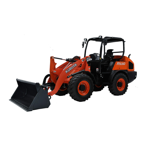
OPERATOR'S MANUAL
KUBOT A
WHEEL LOADER
1BBABBKAP0460
READ AND SAVE THIS MANUAL
MODELS R530 ・ R630
1BBABBKAP0450

Advertisement

Table of Contents
loading

Summary of Contents for Kubota R530

  • Page 1 1000 Kubota Drive, Grapevine, TX 76051 Telephone : 888-4KUBOTA Canada : KUBOTA CANADA LTD. 5900 14th Avenue, Markham, Ontario, L3S 4K4, Canada Telephone : (905)294-7477 WHEEL LOADER France : KUBOTA EUROPE S.A.S 19-25, Rue Jules Vercruysse, Z.I. BP88, 95101 Arɡenteuil Cedex, France Telephone : (33)1-3426-3434 Italy : KUBOTA EUROPE S.A.S Italy Branch Via Grandi, 29 20068 Peschiera Borrome (MI) Italy Telephone : (39)02-51650377 Germany : KUBOTA BAUMASCHINEN GmbH MODELS R530 ・ R630 Steinhauser str, 100, 66482 Zweibrucken Rheinlandpfalz Germany Telephone : (49)6332-4870100 U.K. : KUBOTA (U.K.) LTD. Dormer Road, Thame, Oxfordshire, OX9 3UN, U.K. Telephone : (44)1844-214500 Australia : KUBOTA AUSTRALIA PTY LTD. 25-29 Permas Way, Truɡanina, VIC 3029, Australia Telephone : (61)-3-9394-4400 Malaysia : KUBOTA MALAYSIA SDN. BHD. No.3 Jalan Sepadu 25/123 Taman Perindustrian Axis, Seksyen 25, 40400 Shah Alam, Selanɡor Darul Ehsan Malaysia Telephone : (60)3-736-1388 Philippines : KUBOTA PHILIPPINES, INC. 232 Quirino Hiɡhway, Baesa, Quezon City 1106, Philippines Telephone : (63)2-422-3500...
  • Page 2 Other states or federal areas may have similar laws. Canadian Electromagnetic Compatibility (EMC): This machine complies with Industry Canada ICES-002. R530/R630 English (U.S.A.)
  • Page 3 UNIVERSAL SYMBOLS As a guide to the operation of your machine, various universal symbols have been utilized on the instruments and controls. The symbols are shown below with an indication of their meaning. Safety Alert Symbol Read the Operating Instructions Engine Oil-Pressure Battery Charging Condition Power mode...
  • Page 4 FOREWORD You are now the proud owner of a KUBOTA wheel loader. This wheel loader is a product of KUBOTA quality engineering and manufacturing. It is made of fine materials and under a rigid quality control system. It will give you long, satisfactory service.
  • Page 5: Table Of Contents

    CONTENTS SAFE OPERATION .................... 1. BEFORE OPERATING THE WHEEL LOADER ..........1 2. ENSURE THE DURABILITY OF THE AXLE SUSPENSION....... 3 3. OPERATING THE MACHINE ................4 4. TRAVELING......................5 5. AFTER OPERATION ................... 6 6. SAFE LOADING AND TRANSPORT..............7 7.
  • Page 6 CONTENTS Steering Frame Lock ...................... 26 Control Lever Lock......................26 Auxiliary Port Lever Lock ....................27 CABIN TYPE MACHINE ..................27 Front Wiper / Washer Switch ..................27 Rear Wiper/ Washer Switch................... 28 Interior Lamp........................28 Working Light Switch ...................... 28 Opening/Closing of CABIN Door ..................
  • Page 7 CONTENTS Neutral Switch......................... 50 Direction Switch ......................51 Speed Control Switch ..................... 52 Engine Speed Control Knob ................... 53 Turning..........................53 Deceleration on a Slope ....................53 Traveling on Rough Roads ..................... 54 Traveling on Snow ......................54 STOPPING......................54 OPERATION OF THE LIFT ARM ................
  • Page 8 CONTENTS Checking hydraulic oil level .................... 87 Checking the fuel and replenishing the wheel loader ............. 88 Checking coolant level and replenishing ................ 89 Checking and replenishment of oil in the brake fluid reservoir ........89 Grease fittings......................... 90 Checking tire pressure, wear and wheel nuts..............91 Checking and cleaning the radiator and oil cooler............
  • Page 9 CONTENTS Checking alternator and starter motor ................106 EVERY 3000 SERVICE HOURS ................. 106 Checking EGR System ....................106 Checking Turbocharger ....................106 Cleaning Diesel Particulate Filter (DPF) ............... 106 ANNUAL SERVICE....................106 Checking electrical leads and terminals ............... 106 Checking Exhaust Manifold (Cracks, Gas, Leakage and Mounting Screw) ....
  • Page 11: Safe Operation

    Structure)/FOPS(Falling-Object Protective Structure) 9. Never operate the machine or any equipment while and a seat belt have been installed by KUBOTA. under the influence of alcohol or other drugs, or while Always use the seat belt when the machine is fatigued.
  • Page 12 SAFE OPERATION 13. Do not use the bucket or any other parts of the 16. Carry out the following procedure in order to lift the attachments to pull anything. machine. A Attach the steering frame lock. 14. Carry out the following procedure in order to change the attachment.
  • Page 13: Ensure The Durability Of The Axle Suspension

    (1) and bolts (2) on the front and rear axle. Please contact your KUBOTA dealer. (1) Lugs (Both sides) A Use only a nylon sling or chain that is capable of holding the weight of the machine.
  • Page 14 SAFE OPERATION 3. OPERATING THE MACHINE 19. Do not go up or down a 30 or steeper hill. Otherwise, the machine may skid sideways or turn on its side. 1. Get on and off safely when entering or leaving the If the ground is not level or is soft, limit the slope below operator’s cab.
  • Page 15: Traveling

    If dust which contains crystalline silica is present, there (2) Fully tilt the bucket. are guidelines which should be followed: (3) [R530] 1. Be aware of the potential health effects of crystalline Lock the control lever and the auxiliary port lever silica and that smoking may add to the damage.
  • Page 16: After Operation

    SAFE OPERATION 8. If the engine should stall on a slope, apply the brake to 5. AFTER OPERATION hold the machine in its present position and then lower 1. When getting off the machine, always stop the engine, the bucket to the ground and attempt to restart the lower the bucket and attachment to the ground, engine.
  • Page 17: Safe Loading And Transport

    SAFE OPERATION 6. SAFE LOADING AND TRANSPORT 6. After loading the machine on the truck bed, do the following. 1. When loading or unloading the machine on or from a A Check to see that the machine’s center of gravity truck or trailer, be sure to use strong ramps.
  • Page 18: Servicing The Machine Safely

    SAFE OPERATION 7. SERVICING THE MACHINE SAFELY 1. Before checking, adjusting or cleaning the machine parts, or leaving the machine, observe the following items. A Stop the engine. A Lower the bucket and attachment to the ground. A Release the hydraulic pressure in the hydraulic system by operating the control levers.
  • Page 19 (3) Magnifying glass 15. TOWING IN CASE OF DEFECTS If the loader breaks down and must be towed, call your (1) Bolt nearest KUBOTA dealer. Proceed as follows in case of an (2) Spacer emergency. (3) Rear axle cover (1) Before towing 1.1 To release the negative brake, loosen the two...
  • Page 20 20. If you have questions about the correct disposal or storage of refuse and toxic waste, contact your KUBOTA dealer or a local waste management contractor. 21. Do not open high-pressure fuel system. High-pressure fluid remaining in fuel lines can cause serious injury.
  • Page 21 SAFE OPERATION 28. Fire prevention Wheel Loader some attachments have components that are at high temperatures under normal operating conditions. The primary source of high temperatures is the engine and exhaust system. The electrical system, if damaged or incorrectly maintained, can be a source of arcing or sparks. The following fire prevention guidelines will help to keep your equipment up and running efficiently and keep the risk of fire to a minimum.
  • Page 22: Danger And Warning Labels

    SAFE OPERATION 8. DANGER AND WARNING LABELS...
  • Page 23 SAFE OPERATION...
  • Page 24 SAFE OPERATION...
  • Page 25 SAFE OPERATION...
  • Page 26 SAFE OPERATION...
  • Page 27: Care Of Danger, Warning And Caution Labels

    2. Clean danger, warning and caution labels with soap and water, dry with a soft cloth. 3. Replace damaged or missing danger, warning and caution labels with new labels from your local KUBOTA dealer. 4. If a component with a danger, warning and caution label affixed is replaced with new part, make sure a new label is attached in the same location as the replaced component.
  • Page 29: Servicing Of Wheel Loader

    SERVICING OF WHEEL LOADER SERVICING OF WHEEL LOADER Your KUBOTA dealer is always ready to help so that your wheel loader offers the best performance. After having carefully read these instructions, you will realize that much of the routine maintenance can be done by yourself.
  • Page 30 SERVICING OF WHEEL LOADER (1) Engine serial No.
  • Page 31: Specifications

    SPECIFICATIONS SPECIFICATIONS SPECIFICATION TABLE Model R530 Type Canopy *Operating weight kg (lbs.) 4330 (9546) 4505 (9932) Bucket capacity (cu.yd.) 0.65 (0.85) Manufacturer KUBOTA Model Water-cooled V2607-CR-E4 Horse power (SAE J1995) kW/rpm (HP/rpm) 38.0 / 2400 (51.0 / 2400) Horse power (ISO 9249, SAE J1349) kW/rpm (HP/rpm) 35.7 / 2400 (47.9 / 2400)
  • Page 32: Operating The Machine

    *Operating weight kg (lbs.) 4755 (10483) 4930 (10869) Bucket capacity (cu.yd.) 0.77 (1.0) Manufacturer KUBOTA Model Water-cooled V2607-CR-TE4 Horse power (SAE J1995) kW/rpm (HP/rpm) 48.0 / 2400 (64.4 / 2400) Horse power (ISO 9249, SAE J1349) kW/rpm (HP/rpm) 45.6 / 2400 (61.2 / 2400)
  • Page 33: Description Of Machine Parts

    DESCRIPTION OF MACHINE PARTS DESCRIPTION OF MACHINE PARTS DEPICTED CONTENTS (1) Lift arm (6) Bucket cylinder (11) Turn signal light / Clearance light (2) Bell crank (7) Lift cylinder (12) Working light (3) Bucket (8) ROPS/FOPS CANOPY (13) Fuel tank cap (4) Front wheel (9) ROPS/FOPS CABIN (14) Lift arm support...
  • Page 34 DESCRIPTION OF MACHINE PARTS DEPICTED CONTENTS (16) Towing pin (17) Rear combination light (Turn signal, Tail light, Brake light, Back light) (18) Rear working light (option) (19) Rotary beacon (option)
  • Page 35: Instrument Panel And Control Elements

    INSTRUMENT PANEL AND CONTROL ELEMENTS INSTRUMENT PANEL AND CONTROL ELEMENTS B Switch [R530] DEPICTED CONTENTS (1) Horn switch (10) Speed control switch (down) (2) Turn signal switch (11) Speed control switch (up) (3) Hazard light switch (12) Neutral switch (4) User setting switch...
  • Page 36 INSTRUMENT PANEL AND CONTROL ELEMENTS [R630] DEPICTED CONTENTS (1) Horn switch (14) Float switch (2) Turn signal switch (15) AUX hold switch (3) Hazard light switch (16) Attachment unlock switch (4) User setting switch (17) Direction switch (5) Display selector switch (18) AUX port variable switch (6) AUX port enable switch (19) Speed control switch (down)
  • Page 37 INSTRUMENT PANEL AND CONTROL ELEMENTS B Control Pedals and Levers [R530] DEPICTED CONTENTS (1) Steering wheel (2) Multi function operating lelver (control lever) (3) Control lever lock (4) Auxiliary port lever (5) Auxiliary port lever lock (6) Engine speed control knob...
  • Page 38 INSTRUMENT PANEL AND CONTROL ELEMENTS [R630] DEPICTED CONTENTS (1) Steering wheel (2) Multi function operating lever (control lever) (3) Inching and brake pedal (4) Accelerator pedal [Option] (5) Brake pedal...
  • Page 39 INSTRUMENT PANEL AND CONTROL ELEMENTS B Instrument Panel [R530] DEPICTED CONTENTS (1) Glow plug indicator (15) Periodic check indicator (2) Battery charge indicator (16) Hazard / Turn signal indicator (3) Engine oil pressure warning indicator (17) Parking brake indicator (4) Water separator filled-up indicator...
  • Page 40 INSTRUMENT PANEL AND CONTROL ELEMENTS [R630] DEPICTED CONTENTS (17) Forward, backward and neutral indicator (1) Glow plug indicator (18) Periodic check indicator (2) Battery charge indicator (19) Hazard / Turn signal indicator (3) Engine oil pressure warning indicator (20) Parking brake indicator (4) Water separator filled-up indicator (21) Differential lock indicator (5) Clock setting request indicator...
  • Page 41: Checks Before Start

    A Go around the machine and check for visual damage lights off. and wear. A Check coolant level. (See "DAILY CHECK" in [R530] "PERIODIC SERVICE" section.) A Check fuel level. A Check engine oil level. A Check hydraulic fluid level.
  • Page 42: Starter Switch

    CHECKS BEFORE START BStarter Switch BTurn Signal Switch A [STOP] Operate the turn signal switch to the right or left according The key can be inserted at the "STOP" position. to the direction in which the machine is to be turned. The A [RUN] corresponding turn signal will blink.
  • Page 43: Headlight Switch

    BHazard Lamp Switch Press the hazard lamp switch for the hazard lamps to blink. To avoid personal injury or death: [R530] A For night operation, keep all machine mounted lights operating. Check for burned out lights and replace immediately. The switch has 3 positions. When positioned on your side, the lights stay off.
  • Page 44: Attachment Unlock Switch

    Inhibit mode and the Parked Regeneration The quick coupler is ready for unlocking only while the mode. For detail procedure, refer to page 35 to 39. switch is depressed. For detail procedure, refer to page 66 [R530] to 68. [R530] [R630]...
  • Page 45: Differential Lock Switch

    CHECKS BEFORE START BDifferential Lock Switch BDisplay Selector Switch Press the display selector switch. The electronic meter's LCD will change from one indication mode to the other. Change the 3-mode display according to your jobs. To avoid personal injury or death due to loss of steering control: A Do not lock/unlock the differential while the vehicle is working...
  • Page 46 CHECKS BEFORE START C Setting the clock [Setting the month] [Selecting the clock setting mode] 1. Press the user setting switch. 2. Select the clock setting mode by pressing the display selector switch and the clock setting request indicator " " on the instrument panel lights up. Press user setting switch and the numeric setting will be smaller.
  • Page 47: Battery Charge Indicator

    CHECKS BEFORE START [Setting the hour] BBattery Charge Indicator This warning indicator lights up if the charging system fails with the engine running. When the starter switch is turned to "RUN" with the engine off, the indicator lights up, and when the engine starts, the indicator goes out.
  • Page 48: Engine Oil Pressure Indicator

    CHECKS BEFORE START BEngine Oil Pressure Indicator BGrow Plug Indicator The engine oil pressure warning indicator lights up due to With the starter key at the "RUN" position, the engine's failure of the lubricating system with the engine running. preheat status is indicated. When the starter switch is turned to "RUN"...
  • Page 49: Lcd For Normal Operation

    CHECKS BEFORE START C Fuel level audible indication switch (when BLCD for Normal Operation refueling) 1. With the starter key at the "STOP" position, press the C Fuel gauge fuel level audible indication buzzer, and the fuel level can be checked with buzzer sound. 2.
  • Page 50: Lcd For Warning

    CHECKS BEFORE START C Coolant Temperature Gauge BLCD for Warning C Engine oil pressure warning indicator The engine oil pressure warning indicator lights up due to To avoid personal injury or death: failure of the lubricating system with the engine running. A Do not open the radiator cap during or just after When the starter key is turned to "RUN"...
  • Page 51: Warning Indicator

    A Warnings and errors are displayed and an alarm buzzer beeps. A Let your KUBOTA dealer inform you of details concerning care and maintenance. (1) Warning indicator (red) (2) Warning message...
  • Page 52: Hydraulic Lock Switch

    CHECKS BEFORE START BAUX Port Variable Switch [R630] With the AUX port unlocked, the hydraulic oil flow rate varies depending on the tilt angle of the switch. BHydraulic Lock Switch To avoid personal injury or death: A To avoid injuries, check safety aspects all around the machine.
  • Page 53: Float Switch

    CHECKS BEFORE START SAFETY LEVERS AND APPLIANCE A Aux hold switch will be cancelled, if you operate AUX BSafety Key Start System port variable switch when press aux hold switch. This is the safety system to prevent the machine from moving suddenly.
  • Page 54: Steering Frame Lock

    CHECKS BEFORE START [R530] BControl Lever Lock To avoid personal injury or death: A When dismounting the machine or when servicing the machine, be sure to stop the engine, lower the bucket and the attachment to the ground, release the hydraulic pressure in the hydraulic system by operating control levers.
  • Page 55: Auxiliary Port Lever Lock

    This lock is used to lock the auxiliary port lever. With the such conditions. auxiliary port lever in neutral, forward or backward position, operate the lock. [R530] (1) Front wiper / washer switch (A) "Position " (B) "Position 0" (C) "Position I"...
  • Page 56: Rear Wiper/ Washer Switch

    CHECKS BEFORE START BRear Wiper/ Washer Switch BInterior Lamp To move the rear wiper, turn on the switch for the rear Press the lamp itself, and the lamp lights up. Press the wiper when the starter key in position "RUN". A further lamp again to turn it off.
  • Page 57: Opening/Closing Of Cabin Door

    CHECKS BEFORE START BOpening/Closing of CABIN Door BOpening/Closing of Side CABIN Window 1. Unlock the CABIN door and pull the knob. Open the 1. Press the release button and pull the grip to unlock the CABIN door fully until fixed into place. side CABIN window and push it by release lever to 2.
  • Page 58: Emergency Hammer

    CHECKS BEFORE START AIR CONDITIONER BEmergency Hammer BAirflow Air in the CABIN and fresh air introduced into the CABIN flow as shown below. Adjust the eleven air ports to obtain To avoid personal injury or death: the desired condition. A When breaking the window pane, close your eyes and cover them with an arm.
  • Page 59 CHECKS BEFORE START C How to change the filter A Do not pour water directly into the fresh air port while There are 3 filters: 2 for RECIRCULATION and 1 for washing the vehicle. FRESH AIR. To replace these filters, loosen the knob A During the summer, turn the heater valve clockwise to bolts first and then remove the covers as shown below.
  • Page 60: Air Control Vent

    CHECKS BEFORE START BAir Control Vent BControl panel C Dashboard air outlet The dashboard air outlets can be independently adjusted as required. (1) Air conditioner switch (3) Temperature control dial (2) Indicator light (4) Blower switch C Air Conditioner Switch and Indicator Light (1) Air outlets (A) "OPEN"...
  • Page 61: Operation

    CHECKS BEFORE START BOperation C Heating 1. Adjust the blower (1/2/3) switch and the temperature control dial to achieve the desired temperature level. C Dehumidifying-heating 1. Press and turn on the air-conditioner switch. 2. Turn on the blower (1/2/3) switch. 3.
  • Page 62: Operation Of The Engine

    OPERATION OF THE ENGINE OPERATION OF THE ENGINE EXHAUST AFTERTREATMENT DEVICES To avoid personal injury or death: A To avoid the danger of exhaust fume (carbon To avoid personal injury or death: monoxide) poisoning, do not operate the A During Diesel Particulate Filter...
  • Page 63: Handling Points

    OPERATION OF THE ENGINE A When the DPF has trapped a specific amount of BDPF Regeneration Process particulate matter (PM), the engine computer starts This system has "Parked Regeneration" in which the DPF the process of regeneration or burning of soot regenerates while the machine is parked and "Automatic collected by the filter.
  • Page 64: Regeneration Operating Procedure

    OPERATION OF THE ENGINE Operating Procedure for Auto Regeneration Mode (1) DPF switch (3) Parked regeneration indicator (2) Regeneration indicator (4) Engine warning indicator BRegeneration Operating Procedure 1. The machine has been set to Auto Regeneration Mode by default.. Switch lamp OFF: Auto Regeneration Mode activated. Switch lamp ON: Inhibit Mode activated.
  • Page 65: Pm Warning Level And Required Procedures

    Immediately move the machine to a safe Sounds constantly "ON". place and place in park, turn "OFF" engine. Engine output: 50% Contact your local KUBOTA Dealer. A At this level, never continue to operate the machine otherwise damage may result to the DPF and engine.
  • Page 66 Operating Procedure for Parked Regeneration 1. Park the machine in a safe area away from buildings, people, and animals. 2. Push the parking brake switch. 3. [R530] Lock the control lever. Set the AUX port lever to neutral position. [R630] Activate the hydraulic lock switch.
  • Page 67: Regeneration Operating Procedure

    OPERATION OF THE ENGINE Operating Procedure for Inhibit Mode (1) DPF switch (3) Parked regeneration switch (5) Parked regeneration indicator (2) Inhibit lamp (4) Regeneration indicator (6) Engine warning indicator BRegeneration Operating Procedure 1. The machine has been set to Auto Regeneration Mode by default.. Switch lamp ON: Inhibit Mode activated.
  • Page 68: Pm Warning Level And Required Procedures

    Immediately move the machine to a safe Sounds constantly "ON". place and place in park, turn "OFF" engine. Engine output: 50% Contact your local KUBOTA Dealer. A At this level, never continue to operate the machine otherwise damage may result to the DPF and engine.
  • Page 69: Tips On Dpf Regeneration

    OPERATION OF THE ENGINE BTips on DPF Regeneration STARTING THE ENGINE A Operation [R530] The higher in speed or load the engine operates, the higher the exhaust temperature rises. As a result, 1. Lock the control lever and the auxiliary port lever.
  • Page 70: Checkpoints After Starting The Engine

    A Warning indicator for engine oil lights up during operation. A In these cases, the machine must be checked and serviced by your local KUBOTA dealer. (1) Battery charge indicator (2) Engine oil pressure warning indicator 4. Turn the key to the "START" position and release after the engine has started.
  • Page 71: Starting The Engine Under Cold Conditions

    OPERATION OF THE ENGINE STARTING THE ENGINE UNDER COLD STOPPING THE ENGINE CONDITIONS Start the engine in the following manner; To avoid personal injury or death: 1. Turn the starter switch to the "RUN" position (glow A Do not keep the bucket or attachments in the position) and hold until the indicator lamp has gone lifted position, as a person could accidentally out.
  • Page 72: Starting With An Auxiliary Battery

    OPERATION OF THE ENGINE STARTING WITH AN AUXILIARY BATTERY A This machine has a negative (-) ground 12 Volt starting system. A Only use the same voltage when using an auxiliary battery. To avoid personal injury or death: A Using a higher voltage will cause serious damage to A Battery gases can explode.
  • Page 73: Operation Of The Machine

    OPERATION OF THE MACHINE OPERATION OF THE MACHINE In case of a power cross-over, leave the danger zone with the wheel loader, if possible, by taking suitable measures. If this is not possible, do not leave the operator's place, To avoid personal injury or death: warn any approaching persons of the danger, and have A The safety instructions (page -) must be...
  • Page 74: Starting

    OPERATION OF THE MACHINE C Horizontal seat adjustment STARTING Pull the horizontal seat adjustment lever up (A) and move the seat to the desired position by moving it forward or back, then release the lever. To avoid personal injury or death: C Seat height adjustment A Mount the machine and dismount the machine The seat height can be adjusted to several stop...
  • Page 75: Seat Belt

    OPERATION OF THE MACHINE BSeat Belt BTilt Steering Adjustment To avoid personal injury or death: To avoid personal injury or death: A Always use the seat belt with a ROPS/FOPS A Do not adjust the steering wheel while the protection structure. Adjust the seat to the machine is in motion.
  • Page 76: Selection Of The Driving Mode

    OPERATION OF THE MACHINE C Attachment mode (ATT mode) [R630] The ATT mode proves best with attachments, like SELECTION OF THE DRIVING MODE sweepers and mowers, which need enough hydraulic flow but low traveling speed. In this mode, the hydraulic flow This machine has 4-type driving mode.
  • Page 77: Setting Procedure

    Now the P mode indicator lights up. Press it again, and the machine returns to the N mode and the P 1. [R530] mode indicator goes out. Release the control lock lever. [R630] Deactivate the hydraulic lock switch.
  • Page 78: Accelerator Pedal

    OPERATION OF THE MACHINE BAccelerator Pedal BInching and Brake Pedals This pedal controls engine rpm. The more the pedal is Press either pedal down slightly, then the HST pump pressed, the greater the engine rpm. comes in neutral and cuts off the engine power on the way of the transmission, that is so-called dynamic brake, unique to HST (Hydrostatic Transmission).
  • Page 79: Direction Switch

    OPERATION OF THE MACHINE C To move backward: BDirection Switch Move the direction switch backward and press the accelerator pedal. This switch is used for changing the machine's running direction, forward or back. A When the machine begins to travel "BACKWARD", the back buzzer starts sounding.
  • Page 80: Speed Control Switch

    BSpeed Control Switch Two speed control switches serve to change the top limit of maximum speed in 5 steps. [R530] The maximum speed with the engine just started has 2 speed control switches serve to change maximum been factory-set at 20 km/h (12.4 mph).
  • Page 81: Engine Speed Control Knob

    OPERATION OF THE MACHINE [R530] BTurning BEngine Speed Control Knob 1. Pull up the engine speed control knob and the engine To avoid personal injury or death: revs up. A Do not turn sharply at high speeds. It is 2. To stop the engine, push down the engine speed dangerous.
  • Page 82: Traveling On Rough Roads

    OPERATION OF THE MACHINE STOPPING BTraveling on Rough Roads To avoid personal injury or death: A Choose flat and level ground for parking the To avoid personal injury or death: A Slow down when turning on rough uneven machine. It is important to lower the bucket to terrain and slopes to avoid tip over.
  • Page 83: Operation Of The Lift Arm

    OPERATION OF THE MACHINE C To raise the lift arms OPERATION OF THE LIFT ARM Pull the control lever backward. C To lower the lift arms: Push the control lever forward. And push the control lever to B, fix the float position. (1) Control lever (A) "RAISE"...
  • Page 84: Operation Of The Bucket

    OPERATION OF THE MACHINE C To dump: OPERATION OF THE BUCKET Tilt the control lever to the right. C To roll back: Tilt the control lever to the left. (1) Control lever (A) "DUMP" (1) Control lever (A) "ROLL BACK" A To stop the bucket operation, return the control lever to the neutral position.
  • Page 85: Auxiliary Port Operation

    OPERATION OF THE MACHINE [R530] A When the auxiliary port is not used for a long period, dirt particles can settle in the lower part of the auxiliary AUXILIARY PORT OPERATION port lines. When the plugs on the auxiliary port lines are removed to connect attachments, drain approx.
  • Page 86: Auxiliary Port Operation

    OPERATION OF THE MACHINE [R630] AUXILIARY PORT OPERATION The auxiliary port enable switch is used to operate hydraulic attachment such as 4in1 bucket. BSelecting the Action Modes The AUX port has been factory-set to only one mode (Mode 1). As necessary, up to six action modes can be preset. Each time the AUX port enable switch is pressed, the action modes change over one after another.
  • Page 87: Aux Port Handling Procedure

    OPERATION OF THE MACHINE BAUX Port Handling Procedure 3. Push the AUX port enable switch. 1. Turn the starter key to the "RUN" position. Let the engine warm up after start-up for approx. 10 minutes under no load conditions. (1) AUX port enable switch (2) AUX operation indicator 4.
  • Page 88: Setting The Maximum Flow Volume

    OPERATION OF THE MACHINE BSetting the Maximum Flow Volume The AUX port has been factory-set to one action mode. The action modes 2, 3, 4 and 5 can also be preset. C How to make the settings 1. With the starter key at the "RUN" position, press the user setting switch.
  • Page 89 OPERATION OF THE MACHINE 4. Press the display selector switch for a long time to go to the next port and make the settings for this port. (A) "Left side port" (B) "Right side port" 5. Press the user setting switch for a long time to go back to step 2 to make settings for the next action mode.
  • Page 90 OPERATION OF THE MACHINE...
  • Page 91: How To Release Pressure Trapped In The Hydraulic System

    OPERATION OF THE MACHINE HOW TO RELEASE PRESSURE TRAPPED 3. Make sure that the flow volume in all the AUX ports is not minimized. IN THE HYDRAULIC SYSTEM If the pressure is removed after minimizing the flow 1. Lower the attachments to the ground and activate the volume in the AUX port, release pressure is not hydraulic lock switch.
  • Page 92: Mechanical Quick-Hitch

    OPERATION OF THE MACHINE MECHANICAL QUICK-HITCH BAttaching Attachments This machine utilizes a quick-hitch for easy connection and disconnection of various attachments. By replacing the front attachments, this machine can be used in agriculture, raising stock, landscaping, gardening and snow removal as well as general civil engineering and construction work.
  • Page 93: Detaching Attachments

    OPERATION OF THE MACHINE 7. Visually verify when pushing the quick-hitch levers into locked position that the lock pins protrude through the slot. 8. When attaching different attachments visually inspect for broken or damaged pins. If broken or damaged pins are found, replace before using. Use of broken pins may result in detachment or deformation, causing loss of performance, personal injury or death.
  • Page 94: Quick Coupler (Hydraulic)

    (B) Press forward (3) Attachment unlock switch which are operated with the attachments and spare parts specified by KUBOTA. 2. Position the machine squarely in front of the attachment and tilt the quick-coupler forward approx. A Attachments should be located on a level, firm surface 15 and align the upper attachment points of the bracket.
  • Page 95 OPERATION OF THE MACHINE 4. [R530] Lock the attachment by pushing the auxiliary port lever forward in order to move the locking pins out into locking position. (1) Auxiliary port lever (A) Push forward [R630] Lock the attachment by moving the auxiliary port variable switch forward in order to move the locking pins out into locking position.
  • Page 96 3. Reverse away from the attachment. that the front end of machine rise slightly. C Detaching Disconnecting the front attachments as follows. 1. [R530] Pull the auxiliary port lever backward while pressing the attachment unlock switch forward in order to retract the locking pins.
  • Page 97: Connecting And Disconnecting The Hydraulic Hose

    1. Before starting to work, apply the parking brake and stop the engine. 2. Starter switch in RUN position. 3. [R530] Operate the auxiliary port lever several stroke to release any hydraulic pressure remaining in the circuits.
  • Page 98: Using The Inching And Brake Pedal According To The Job

    OPERATION OF THE MACHINE C To approach slowly 1. Press the inching and brake pedal slightly while BUsing the Inching and Brake Pedal pressing accelerator pedal. machine According to the Job approaches slowly. 2. The machine can slowly approach an object by accelerator pedal regulation only, without inching and brake pedal operation.
  • Page 99: Typical Jobs Using A Wheel Loader

    OPERATION OF THE MACHINE TYPICAL JOBS USING A WHEEL LOADER Below are some typical jobs performed using a wheel loader. The machine can also be used to perform other jobs by connection with various attachments. To avoid personal injury or death: A When transporting a load, keep the loader bucket as low as possible to avoid tipping over.
  • Page 100: Digging And Loading

    OPERATION OF THE MACHINE C Digging and loading from flat ground BDigging and Loading 1. Direct the bucket blade slightly downward and lower the bucket as you advance the machine. The recommended digging depth per pass is between C Loading a sand pile 10 and 15cm (4-6").
  • Page 101: Refilling

    OPERATION OF THE MACHINE BRefilling BLoading onto a Truck Examine the job site situation and choose the efficient 1. Direct the bucket horizontally and push the piled sand loading method that minimizes the swivel angle and toward the ditch. moving distance. 2.
  • Page 102: Anti-Theft Device (For Kcl Only)

    OPERATION OF THE MACHINE ANTI-THEFT DEVICE (FOR KCL ONLY) C How to register a black key (individual key) with the machine (When a black key is lost) BAnti-Theft Device This machine is equipped with an anti-theft device, which allows you to start the engine with the registered key alone.
  • Page 103 If by any chance it gets lost, promptly contact your dealer. A Use the Kubota-specified key ring to hold the black key or the red key. Any unspecified key rings may interfere with the signal transfer between the key and the key switch, possibly failing to start the engine or to register a key properly.
  • Page 104: Transport By Truck

    TRANSPORT BY TRUCK TRANSPORT BY TRUCK B Loading on and from a truck 2. Fix the ramps securely to the truck so they cannot slip. To avoid personal injury or death: A When loading the machine on or unloading from a truck, be sure to use strong ramps. Never use wet lumber, etc.
  • Page 105 TRANSPORT BY TRUCK B Transportation To avoid personal injury or death: A Before transportation, do the following to prevent the machine from moving during transportation. A Check to see that the machine’s longitudinal axis aligns with that of the truck bed. A Stop the engine and remove the key.
  • Page 106: Lifting The Machine

    LIFTING THE MACHINE LIFTING THE MACHINE To avoid serious injury or death: A The instructions for safe lifting are described here. Read these instructions carefully before lifting the machine. Make sure that the operating personnel read operator's manual carefully before lifting. A Select a firm level surface, lower the working equipment to the ground, stop the engine and set the control lever lock and the auxiliary port lever lock to the...
  • Page 107: Handling Loader In Cold Weather

    HANDLING LOADER IN COLD WEATHER HANDLING LOADER IN COLD WEATHER PREPARATIONS FOR COLD WEATHER AFTER-OPERATION DIRECTIONS 1. Change engine oil to one of low viscosity suitable for After operation, be sure to remove mud or water from the use in cold weather. machine’s body.
  • Page 108: Maintenance

    A Before servicing or checking the machine, do the following procedures. A If the machine cannot be operated and must be towed, A Stop the engine. please contact your local KUBOTA dealer for A Set the direction switch to the neutral information about correct towing procedures. position.
  • Page 109: Maintenance Intervals

    MAINTENANCE MAINTENANCE INTERVALS Hour meter indicator Ref. Check points Measure Interval page check Daily check Coolant change every 2 years Fuel check Daily check check Daily check Engine oil change every 500 hrs check Daily check Hydraulic oil replace every 1000 hrs Radiator and oil Cooler check Daily check...
  • Page 110 MAINTENANCE Hour meter indicator Ref. Check points Measure Interval page Alternator and starter motor check every 2000 hrs EGR system check every 3000 hrs Turbo charger (R630) check every 3000 hrs clean every 3000 hrs AFS (Air flow sensor) check every 1 year Boost sensor (R630) check...
  • Page 111 MAINTENANCE Hour meter indicator Ref. Check points Measure Interval page 1000 check Daily check Coolant change every 2 years Fuel check Daily check check Daily check Engine oil change every 500 hrs check Daily check Hydraulic oil change every 1000 hrs Radiator and oil Cooler check Daily check...
  • Page 112 A The listed items (@ marked) are registered as emission related critical parts by KUBOTA in the U.S.EPA non-road emission regulation. As the engine owner, you are responsible for the performance of the required maintenance on the engine according to the preceding instruction.
  • Page 113: Periodic Service

    PERIODIC SERVICE PERIODIC SERVICE OPENING AND CLOSING OF COVERS BSide cover Insert the key into the key hole, turn it clockwise to unlock the side cover and pull up until it will be held. To avoid personal injury or death from contact with moving parts: [Left side] A Never open the engine cover while the engine...
  • Page 114: Daily Check

    Doing so can increase the If there are any leaks, take proper measures to stop small amount of fuel that gets mixed with the engine them. If repair is impossible, contact your KUBOTA oil, thereby degrading it. dealer.
  • Page 115: Checking Hydraulic Oil Level

    PERIODIC SERVICE BChecking hydraulic oil level To avoid personal injury or death: A Never open the oil port immediately after the engine has stopped or hydraulic oil may rush out, causing scalding. 1. Stop the machine on flat ground and lower the bucket to the ground and roll back the bucket.
  • Page 116: Checking The Fuel And Replenishing The Wheel Loader

    PERIODIC SERVICE BChecking the fuel and replenishing the wheel loader To avoid personal injury or death: A Before refueling, always stop the engine, lower the bucket and attachment to the ground, release the hydraulic pressure in the hydraulic system by operating the control levers. Lock all control levers in neutral, and remove the key.
  • Page 117: Checking Coolant Level And Replenishing

    PERIODIC SERVICE BChecking coolant level and replenishing BChecking and replenishment of oil in the brake fluid reservoir To avoid personal injury or death: A Do not remove radiator cap while coolant is hot. When cool, rotate the cap to the first stop To avoid personal injury or death: to allow excessive pressure to escape.
  • Page 118: Grease Fittings

    PERIODIC SERVICE BGrease fittings To avoid serious personal injury or death: A Keep clear of articulation joint during service work. To avoid personal injury or death: A Before greasing, always stop the engine, lower the bucket and attachment to the ground, release the hydraulic pressure in the hydraulic system by operating the control levers, lock all control levers in neutral, and remove the key.
  • Page 119: Checking Tire Pressure, Wear And Wheel Nuts

    BChecking tire pressure, wear and wheel 1. Start the engine, turn the steering wheel left and right and check the operation. nuts 2. If any abnormality is found, have the steering Refer to the section on "TIRES". inspected further by your KUBOTA dealer.
  • Page 120: Checking Gear Locked Parking Brake

    2.7 meters (8 ft 3 in.) every 10 meters (32 ft 10 SERVICE" in "PERIODIC SERVICE" section.) in.)). If the machine moves, consult your local KUBOTA Dealer. BWashing whole machine Always engage the parking brake before dismounting the wheel loader.
  • Page 121: Cleaning Evacuator Valve

    PERIODIC SERVICE BCleaning evacuator valve BChecking Diesel Particulate Filter (DPF) Open the evacuator valve to get rid of large particles of dust and dirt. Muffler To avoid personal injury or death: A Before checking or cleaning the DPF muffler, stop the engine and wait long enough until it is cooled down.
  • Page 122: Checking Washer Liquid [Cabin Type Only]

    PERIODIC SERVICE BChecking washer liquid [CABIN TYPE BTesting the horn ONLY] Check that the horn works. If the windows washer is switched on with the washer liquid tank empty, the motor may be damaged. Always BChecking the machine for leaks keep the tank filled.
  • Page 123: Every 50 Hours Service

    PERIODIC SERVICE EVERY 50 HOURS SERVICE The factory-installed battery is of non-refillable type. If the indicator turns white, do not quick charge the BChecking the battery condition battery but replace it with new one. Mishandling the battery shortens the service life and adds To avoid the possibility of a battery explosion: to maintenance costs.
  • Page 124: Every 250 Hours Service

    PERIODIC SERVICE EVERY 250 HOURS SERVICE Perform inspection and servicing for every 50 hours of operation at the same time. BGrease fittings To avoid serious personal injury or death: A Keep clear of articulation joint during service work. (1) Battery To avoid personal injury or death: A Before greasing, always stop the engine, lower 1.
  • Page 125: Checking Fan Belt Tension

    PERIODIC SERVICE A If the engine is running with a loose fan belt, the belt may slip, causing engine overheating or insufficient battery recharging. Always keep the fan belt properly tightened. A If the fan belt should break, the battery charge lamp lights up.
  • Page 126: Cleaning And Checking Air Cleaner Element

    PERIODIC SERVICE BCleaning and checking air cleaner BCleaning the filter element element If the filter element is heavily clogged or oily, change it. If it is only dusty, you can clean it with compressed air. Open the engine cover and remove the cover and the outer filter element, clean the filter element, case interior without removing the inner element and reassemble the filter element and cover.
  • Page 127: Replacing Water Separator Filter Element

    PERIODIC SERVICE EVERY 500 HOURS SERVICE BReplacing water separator filter element Perform inspection and servicing for every 50 and 250 1. Set the water shutoff-valve to the "CLOSE" position. hours of operation at the same time. 2. Loosen and remove the cup properly and replace the filter element.
  • Page 128: Replacing The Engine Oil Filter Cartridge

    PERIODIC SERVICE 2. Fill engine oil into the oil port up to the correct level. 3. Idle the engine for a short while. About 5 minutes after BReplacing the engine oil filter cartridge stopping the engine, check the oil level with the oil dipstick.
  • Page 129: Checking And Replenishing Oil In The Front And Rear Axle, Reduction Gear Case

    PERIODIC SERVICE BChecking and replenishing oil in the front and rear axle, reduction gear case To avoid personal injury or death: A Before changing oil in the front and rear axle differential case, always stop the engine and lock the direction switch in neutral. A Always remove the bucket and attachment, and use the lift arm support device when servicing the machine with the loader lift arms raised to...
  • Page 130: Changing The Fuel Filter

    PERIODIC SERVICE EVERY 1000 HOURS SERVICE BChanging the fuel filter Perform inspection and servicing for every 50, 250 and 500 hours of operation at the same time. To avoid personal injury or death: BChanging oil for the front and rear axle A Always stop the engine before changing the case fuel filter.
  • Page 131: Replacing Hst Oil Filter

    PERIODIC SERVICE BReplacing HST oil filter To avoid personal injury or death: A Never remove the filter immediately after the engine has stopped, or hot hydraulic oil may rush out, causing scalding. 1. Loosen the nut located the bottom of the filter and remove the filter.
  • Page 132: Changing Hydraulic Oil And The Suction Filter

    PERIODIC SERVICE 7. Run the engine at idle speed, set the direction switch BChanging hydraulic oil and the suction to the neutral position.Then operate the control lever and the steering wheel for about five minutes. filter Stop the engine and make sure that the oil quantity is sufficient through the oil level gauge.
  • Page 133: Replacing Air Cleaner Element

    PERIODIC SERVICE BAdjusting Engine Valve Clearance Consult your local KUBOTA dealer for this service. EVERY 1500 SERVICE HOURS Perform inspection and servicing for every 50, 250 and 500 hours of operation at the same time. BChecking Injector Tip Consult your local KUBOTA dealer for this service.
  • Page 134: Checking Egr Cooler

    Too much ash build-up adversely affects the DPF performance. Consult your local KUBOTA Dealer to clean up the filter. A To clean up the DPF, a specific machine is required. Do not attempt to clean it in any other way, such as...
  • Page 135: Biennial Service

    PERIODIC SERVICE BChanging coolant BIENNIAL SERVICE Perform inspection and servicing for annual operation at the same time. To avoid personal injury or death: A Never open the plug immediately after the BReplacing fuel hoses and clamps engine has stopped, or hot coolant may rush out, causing scalding.
  • Page 136: Replacing Intake Air Line

    You may get burned. Replace air-conditioner pipes and hoses every two years. If the hoses or pipes are swollen, hard or cracked, they should be replaced. (Consult your local KUBOTA Dealer (1) Hoses for this service.) (2) Hose clamps...
  • Page 137: Service As Required

    PERIODIC SERVICE SERVICE AS REQUIRED [Fuse box A] BElectrical system Damage to cables and loose connections cause malfunctioning and lead to short circuits, leakage and fires. Replace and repair as quickly as possible. C Replacing the fuses To avoid personal injury or death: A Before replacing a fuse, be sure to turn off the starter switch.
  • Page 138 PERIODIC SERVICE [Fuse box B] [Fuse box C] Rating Applied Circuit Rating Applied Circuit Rear wiper, Rear washer Engine ECU Radio AC Blank Electrical outlet Blank Compressor Reverse lamp, Reverse buzzer Quick coupler locking Stop lamp [Slow blow fuse] Highbeam Hazard Head lamp Blank...
  • Page 139: Draining The Fuel Filter

    PERIODIC SERVICE C Replacement procedure 1. Disconnect the negative cord of the battery. BDraining the fuel filter 2. Remove the slow blow fuse case. If the Water separator filled-up indicator lights up and the 3. Open the slow blow fuse case cap and cover then error code (E:9120) appears on the meter panel, remove the bolts and draw out the slow blow fuse (1) immediately take the following steps to drain the filter after...
  • Page 140: Bleeding The Fuel System

    If this should occur, repeat step (2) and step (3). (1) Deficient (2) Correct TIRES (3) Excessive (4) Ground level BHandling tires Type R530 Bucket Pallet forks Tire size To avoid personal injury or death: front rear front rear A Before changing tires, stop the engine, lower 3.0 bar...
  • Page 141: Changing Tires

    PERIODIC SERVICE 1. Insufficient tire pressure. Too small an amount of air in the tire can cause it to BMounting tires have excessive slack, which makes for faster wearing Off-road tires are used to provide strong traction and down of the tread. buoyancy on soft ground.
  • Page 142: Taking Out Of Operation And Storage

    114 TAKING OUT OF OPERATION AND STORAGE TAKING OUT OF OPERATION AND STORAGE To avoid personal injury or death: A Before storing, do the following. Stop the engine, lower the bucket and attachment to the ground, release the hydraulic pressure in the hydraulic system by operating the control levers, lock all control levers in neutral, and remove the key.
  • Page 143: Recommended Oils

    RECOMMENDED OILS RECOMMENDED OILS 1. The hydraulic oil used from the factory was ROWE Hightec Fomula GT. 2. Use engine oil API service classification CJ-4 or CK-4. 3. Use TOTAL TRANSMISSION T.H.F.I. as front and rear axle cases for all seasons. Application Viscosity KTC recommends...
  • Page 144: Biodiesel Fuel (Bdf)

    Consequently, fuel filter performance may be reduced, particularly during cold weather conditions. 8. The KUBOTA Warranty, as specified in the Owner's Warranty Information Guide, only covers defects in product materials and workmanship. Accordingly, any problems that may arise due to the use of poor quality fuels that fail to meet the above requirements, whether biodiesel or mineral oil based, are not covered by the KUBOTA Warranty.
  • Page 145 Fuel line Replace every 1 year Consult your local KUBOTA Dealer for this service. C Long Term Storage: 1. BDF easily deteriorates due to oxygen, water, heat and foreign substances. Do not store B6 through B20 longer than 1 month and B5 longer than 3 months.
  • Page 146: Trouble Shooting

    118 TROUBLE SHOOTING TROUBLE SHOOTING If the machine does not show the desired performance, or when trouble arises, refer to the table below and undertake appropriate measures. Trouble Cause Countermeasure * Check fuel tank and filter. Fuel is too viscous. * Remove impurities and water.
  • Page 147 TROUBLE SHOOTING Trouble Cause Countermeasure Hydraulic oil level too low * Add oil. Lift arms, bucket, Leakages of hoses and / or Hydraulic * Replace hose or joint. drive unit power is joints System too low. Hydraulic unlock switch is not * Press the hydraulic unlock switch.
  • Page 148: List Of Error Code Numbers

    It is impossible to change Speed control switch Immediately contact your local E: 023 the speed setting by the (R530) dealer. speed control switch. Differential lock does not Immediately contact your local E: 024 Differential lock work dealer.
  • Page 149 TROUBLE SHOOTING Machine condition Engine performance Provisional measure Error Code Problem or Failure Number Accele- Engine Machine performance Correction Engine ration output stopped limited limited Immediately contact your local E: 029 AUX port knob (R630) AUX port does not work. dealer.
  • Page 150 122 TROUBLE SHOOTING Machine condition Engine performance Provisional measure Error Code Problem or Failure Number Accele- Engine Machine performance Correction Engine ration output stopped limited limited Immediately contact your local E:9102 SCV system dealer. Intake temperature Immediately contact your local E:9103 sensor system dealer.
  • Page 151 TROUBLE SHOOTING Machine condition Engine performance Provisional measure Error Code Problem or Failure Number Accele- Engine Machine performance Correction Engine ration output stopped limited limited Stop the engine and check and drain the fuel filter. E:9120 Fuel filter water warning If this error code number still appears, immediately contact your local dealer.
  • Page 152 124 TROUBLE SHOOTING Machine condition Engine performance Provisional measure Error Code Problem or Failure Number Accele- Engine Machine performance Correction Engine ration output stopped limited limited Check the fuel level and see if the fuel filter is clogged. E:9303 Engine fuel system (SCV) If this error code number still appears, immediately contact your local dealer.
  • Page 153: Appendix

    (The maintenance message reappears on the hour meter designated next.) A The maintenance (periodic check) message can be automatically disappeared. C In case the service hour meter replaced due to any trouble with it, the meter is set to "0". Contact your KUBOTA dealer for details.

This manual is also suitable for:

R630

Table of Contents