Table of Contents

Subscribe to Our Youtube Channel
Related Manuals for Lissmac MULTICUT 800

Summary of Contents for Lissmac MULTICUT 800
- Page 1 CONSTRUCTION TECHNOLOGY OPERATING MANUAL FLOOR CUTTER MULTICUT 800 LISSMAC Maschinenbau GmbH Lanzstrasse 4 D-88410 Bad Wurzach Telefon +49 (0) 7564 / 307-0 Telefax +49 (0) 7564 / 307-500 lissmac@lissmac.com www.lissmac.com...
- Page 3 Imprint The operating manual is valid for LISSMAC Floor Cutter MULTICUT 800 Version: 08-2016 Translation of the original operating manual Company headquarters: LISSMAC Maschinenbau GmbH Lanzstraße 4 D-88410 Bad Wurzach Tel: +49 (0) 7564 / 307 - 0 Fax: + 49 (0) 7564 / 307 - 500 E-Mail: lissmac@lissmac.com...
-
Page 4: Table Of Contents
Preface to the operating manual This operating manual should make it easier to get to know the machine and make use of its intended applications. The operating manual contains important information on how to operate the machine safely, properly and economically. -
Page 5: Basic Safety Instructions
1. Basic safety instructions 1.1 Warning notices and symbols in this operating manual Danger! Indicates that failure to comply could lead to severe injury or even death. Attention! Indicates that failure to comply could sometimes lead to injuries. Note Indicates that failure to comply leads to damage to the machine or other property. - Page 6 1.2 Basics of intended use 1.2.1 The machine is constructed according to the state of the art and recognised technical safety rules. However, danger to life and limb of the user or third parties, and/or damage to the machine or other property may still arise from its use.
- Page 7 1.4 Personnel choice and personnel qualification; basic responsibilities 1.4.1 Work on the machine must only be performed by reliable personnel. Observe the legal minimum age! 1.4.2 Only use trained or orientated personnel. Establish clear responsibilities of the personnel for operating, changeover, servicing, and repairing the machine! 1.4.3 Make sure that only authorised personnel work on the machine!
- Page 8 1.5.2 Special work while using the machine and maintenance work as well as troubleshooting during operation; disposal 1.5.2.1 Follow all setup, maintenance, and inspection activities and schedules prescribed by the operating manual, including all information about the replacement of parts / assemblies! These activities may only be carried out by experts.
- Page 9 1.7 Transport 1.7.1 Only use lifting gear and load carrying equipment with sufficient lifting capacity during loading work! 1.7.2 Name expert instructors for the lifting process! 1.7.3 Lift the machine only according to the instructions in the operating manual (using attachment points for load-bearing systems, etc.), and with proper lifting accessories! 1.7.4 Only use suitable transport vehicle with sufficient load capacity!
-
Page 10: Machine Description
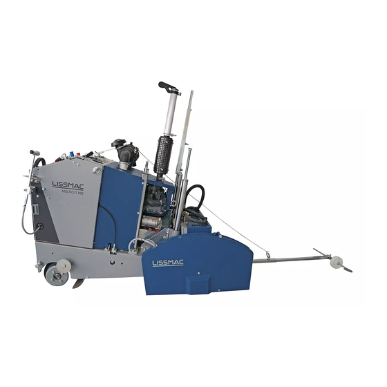
2. Machine description 1.1 Component overview Pos. 1 Steering wheel Pos. 2 Control console Pos. 3 Motor housing Contents: Diesel engine, controls, hydraulic pump Pos. 4 Steering rod Pos. 5 Saw blade protective hood Pos. 6 Water supply Pos. 7 Undercarriage Contents: Steering, gears 1.1 Safety guards... - Page 11 2.3. Technical data MULTICUT 800 G MULTICUT 800 GH Cut depth 315 mm (515 mm) 315 mm (515 mm) Cutting depth setting Electrohydraulic / variable Electrohydraulic / variable Standard saw blade Ø 800 mm (1,200 mm) 800 mm (1,200 mm)
- Page 12 2.6 Rotation speeds MULTICUT 800 G 210693 Ø 500 – 800 mm Ø 700 – 1200 mm 2650 1550 2480 1450 2310 1350 2140 1250 1970 1150 MULTICUT 800 GH 210694 Ø 300 – 550 mm Ø 500 – 800 mm...
-
Page 13: Commissioning
3. Commissioning 3.1 Control console Before starting the floor cutter become familiar with its operation. 20.1... - Page 14 Pos. 10 Water temperature Pos. 11 Motor oil pressure may not burn during operation! Pos. 12 Emergency stop switch Pos. 13 Battery charging control may not burn during operation! Pos. 14 Fuses Pos. 15 Plug sockets for lamps Pos. 16 Water pump on-off Pos.
- Page 15 Shut off the ignition (Pos. 21) Disconnect the water hose Remove exhaust hose (Pos 26) (only MULTICUT 800 GH) Unscrew the ring screw (Pos. 27) and remove the Y- piece from the holder Unscrew the M 10 (Pos. 27.1) ring nut ...
- Page 16 3.4 Preparations for starting Move the floor cutter into position Steering rod (Pos. 4) and saw blade (or rear steering rod) are above the cut line Note 20.1 The feed lever (Pos. 20) must be in the middle position when starting the motor.
-
Page 17: Transport
Floor cutter movement is only permitted with a stationary saw blade. For the MULTICUT 800, the saw blade must be removed! For MULTICUT 800 G and MULTICUT 800 GH the drive lever (Pos. 40) must be in the STOP position! Attention! Release the brakes (Pos. -
Page 18: Operation
5.3 Saw blade selection Danger! No mesh discs may be used. Refer to the prospect “Lissmac Diamond Tools”. Install only saw blades recommended by the manufacturer. 5.4 Cutting depth limits This setting is recommended for several cuts of the same depth ... - Page 19 Standard speed is 1550 1/min v-belt (Pos. 58.4) Remove the guard plate (Pos. 50) Disconnect water supply (only for MULTICUT 800 GH and GH or accessories) on the saw blade shaft Loosen screws (Pos. 57) (left and right) ...
- Page 20 58.4 58.4 58.1 58.3 58.3 58.5 58.5 58.2 58.6...
- Page 21 5.9 Pre-tension brakes Remove cover (Pos. 50) The raster adjustment (Pos. 54) for the brakes enables the brake effectiveness to be changed. e.g. during cutting on inclines The neutral home position is marked in colour...
-
Page 22: Operation With Waste Water Suction
6. Operation with waste water suction 6.1 Operation of waste water suction (only MULTICUT 800 GH) Exhaust can be turned on and off using the lever (Pos. 39) Lever down = exhaust on Lever high = exhaust off 6.2 Clean filter in dirty water container (Pos. 42) (several times daily) Attention! Switch off the motor of the floor cutter. - Page 23 6.3 Flush the exhaust Note Before any longer operational pause (longer than 0.5 hours) rinse the exhaust with water so that no dried dirt is stuck in the system. Switch on the saw blade and joint cutters cooling water (do not saw).
- Page 24 Mount the water supply (Pos. 6) on the other side Turn the steering rod (Pos. 4) Swing the steering wheel out (only MULTICUT 800 GH) Mount the feed lever (Pos. 20) to the adapter (Pos. 36) (unplug cable) Replace the waste water suction (Pos.
-
Page 25: Maintenance
7. Maintenance 7.1 Service when the warning every "x" operating first time daily weekly monthly annually indicator lights up hours Change hydraulic oil (see 6.4) every 2 years – annually for exhaust Check hydraulic hoses and screwed 20 h connections for leaks and damage Lubricate the lubrication points (see 6.3) Check oil level in hydrostatic Check the drive (see 6.7) - Page 26 7.2 Operating materials Diesel motor, see Kubota operating manual Drive oil for the bevel gear drive (Pos. 52) * SAE 90 fully synthetic 1.2 l Lubrication points * Roxana ALU EP2 7.3 Lubrication points Moving parts must be lubricated using the integrated lubrication nipples.
- Page 27 7.4 Hydraulic oil change The system (Pos. 48) is filled with "BP Batran HVAC-68" hydraulic oil by the manufacturer. Old oil can be exhausted at the filling neck of the system. You can also screw off the system and tip it so that the oil runs out.
- Page 28 7.6 Oil change on the feed drive Remove cover (Pos. 55) Screw out the ventilation stopper (Pos. 56) from the feed drive Remove the drain screw (Pos. 63) under the joint cutter Drain the oil and return the screw (Pos. 63) ...
- Page 29 7.8 Control motor cooling water Attention! Danger of burning! Open the cover on the cold motor. Open the cover of the cooler on the upper right of the control console, the filling level must be visible on the cooling water filling neck. ...
- Page 30 7.9.2 Hydrostat V-belt tension 58.7 Remove cover (Pos. 55) Loosen screw (Pos. 58.7) Push the lever rod in the direction of the cooler Pre-tension V-belt with corresponding force Tighten screw (Pos. 58.7)
-
Page 31: Troubleshooting Table
8. Troubleshooting table Error Cause Remedy Move the lever (Pos. 20) into the Feed lever (Pos. 20) not in the middle position middle position Emergency stop (Pos. 12) is Deactivate Emergency stop active (Pos. 12) Motor does not start Fuel tank empty See Kubota operating manual! See Kubota operating manual! Bleed the fuel line... -
Page 32: Service Work
9. Service work Date Operating hours performed maintenance work Signature / stamp... -
Page 33: Warranty
10. Warranty The warranty for this machine is 12 months. For the following listed wear parts the warranty only applies if the wear is not caused by operation. Wear parts are parts that with intended use of the machine have limited operational wear. The wear time is not uniformly specified, it differs according to intensity of use. - Page 37 Manufacturer: LISSMAC Maschinenbau GmbH Lanzstrasse 4 D-88410 Bad Wurzach The technical documentation retained by LISSMAC Maschinenbau GmbH, Lanzstrasse 4, D-88410 Bad Wurzach. Machine The floor cutter is intended for cutting grooves into concrete or asphalt. description: MULTICUT 800 G MULTICUT 800 GH Cutting depth (max.)
Need help?
Do you have a question about the MULTICUT 800 and is the answer not in the manual?
Questions and answers