
Related Manuals for Trox Technik X-AIRCONTROL


Summary of Contents for Trox Technik X-AIRCONTROL
- Page 1 Commissioning and service manual GB/en X-AIRCONTROL Zone control systems Read the instructions prior to performing any task!
- Page 2 TROX GmbH Heinrich-Trox-Platz 47504 Neukirchen-Vluyn, Germany Germany Telephone: +49 2845 202-0 Fax: +49 2845 202-265 Email: E-mail: trox@trox.de Internet: www.trox.de A00000063012, 2, GB/en 11/2021 © TROX GmbH 2017 X-AIRCONTROL Zone control systems...
- Page 3 This document, including all illustrations, is protected by This manual enables operating or service personnel to copyright and pertains only to the corresponding use the X-AIRCONTROL zone control system safely product. and efficiently. Any use without our consent may be an infringement of...
-
Page 4: Table Of Contents
3.8.2 Configuring actuators and sensors ..53 BMS ..............90 3.8.3 Setting the volume flow rate ....54 Connecting X-AIRCONTROL to an air han- 3.8.4 Checking the volume flow rate ..... dling unit (AHU) ..........91 3.8.5 Setting up a supply branch ....55 Setting up MP bus or Modbus actuators .. - Page 5 Table of contents Wiring documents ........104 10.1 Zone master ........10.2 Zone module X-AIR-ZMO-MP ..... 105 10.3 Zone module X-AIR-ZMO-MOD ..106 10.4 Zone module X-AIR-ZMO-ANA ... 107 Index.............. 108 X-AIRCONTROL Zone control systems...
-
Page 6: Safety
1.2 Correct use CAUTION! The X-AIRCONTROL zone control system consists of a Potentially hazardous situation which, if not avoided, zone master and several zone modules plus sensors; it may result in minor or moderate injury. -
Page 7: System Owner's Responsibility
HVAC systems, The system owner has to ensure that all individuals understand any potential hazards related to the work who handle or use X-AIRCONTROL have read and under consideration, and recognise and avoid any risks understood this manual. involved. -
Page 8: Work Area Hazards
1.6 Personal protective equipment WARNING! Health risk due to inadequate personal protective equipment! – Ensure that personnel uses the correct personal protective equipment for the location where the zone control system is installed. X-AIRCONTROL Zone control systems... - Page 9 It prevents entanglement in moving machinery. Safety shoes Safety shoes protect the feet against crushing, falling parts, and from slipping on slippery ground. Safety goggles Safety goggles protect the eyes from flying particles and liquid splashes. X-AIRCONTROL Zone control systems...
-
Page 10: Aircontrol System Description
Cooling Single room control is the smallest unit for X-AIRCONTROL. With this setup, one zone module controls one zone (e.g. a room). Zone modules come in three variants. Make sure that each VAV terminal unit and controller fit the bus system used for the zone module. - Page 11 The set minimum volume flow rates are maintained. Temperature control by means of water-side valves is not affected. Maximum volume flow rate The set maximum volume flow rates are maintained. Temperature control by means of water-side valves is not affected. X-AIRCONTROL Zone control systems...
-
Page 12: Control Of Up To 25 Rooms
The set minimum volume flow rates are maintained. Temperature control by means of water-side valves is not affected. Maximum volume flow rate The set maximum volume flow rates are maintained. Temperature control by means of water-side valves is not affected. X-AIRCONTROL Zone control systems... -
Page 13: Control With 5 Zone Masters
You can connect up to five X-AIRCONTROL zone masters to form a system. You then have to connect the zone masters in a cascade between the 'Zone Master In' input and the 'Zone Master Out' output. You need to connect each X-AIRCONTROL zone master to the same LAN (subnetwork) so that the web server acts as the common inter- face. -
Page 14: Control Of Up To 4 Rooms With An X-Cube Compact
Network access You can use an X-CUBE compact air handling unit to control an X-AIRCONTROL system for up to 4 zones (rooms). In such a case, X-CUBE control (AHU control system) provides the control input signals for fans, volume flow con- trollers and peripheral components. -
Page 15: System Components
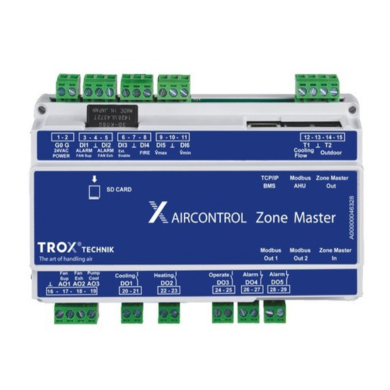
X-AIRCONTROL system description System components > Zone master 2.2 System components 2.2.1 Zone master Fig. 5: X-AIRCONTROL zone master Supply voltage 24 V AC (G0/G) Digital output signal 'B alarm' (DO5) Alarm inputs (DI1/DI2) Digital output signal 'A alarm' (DO4) - Page 16 Override control: volume flow controllers maintain V ┴ DI6 (V ̇ min) Override control: volume flow controllers maintain V Temperature sensor connec- Terminal tions (T1, T2) T1 (Cooling flow) Temperature sensor of cooling circuit ┴ T2 (Outdoor) Outdoor sensor – Not used X-AIRCONTROL Zone control systems...
- Page 17 24 V AC ±10% Power consumption (master) ≤ 5 VA (without any external sensors or actuators) Cable diameter 1.5 mm max. SD card SDHC, 8 GB max. Network properties 192.168.0.201 IP address (factory setting) Subnet 255.255.255.0 (factory setting) X-AIRCONTROL Zone control systems...
- Page 18 Max. load: 50 mA per output Ambient conditions Acceptable relative humidity 10 – 90 % (rh) (no condensation) Max. temperature – operation -20 to +50 °C Max. temperature – storage -30 to +70 °C Protection level IP 20 (EN 60529) X-AIRCONTROL Zone control systems...
-
Page 19: Zone Modules
Supply voltage Terminal (G0) 24 V AC In Input for supply voltage 24 V AC Output of supply voltage 24 V AC to the following zone module 24 V AC Out (up to 3 in series) X-AIRCONTROL Zone control systems... - Page 20 Zone module in section 2 (zone master 2) Zone module in section 3 (zone master 3) Zone module in section 4 (zone master 4) Zone module in section 5 (zone master 5) No area number has been assigned by the zone master X-AIRCONTROL Zone control systems...
- Page 21 2 temperature sensors (supply air, extract air or room air temperature) have been connected Sensor short circuit Room control panel Display Description Room control panel X-AIR-CP-2T has been connected Software update Display Description Software update in progress Important: Do not interrupt the supply voltage! X-AIRCONTROL Zone control systems...
-
Page 22: Mp Bus Output A
GND for volume flow controller MP bus output B Terminal 24 V AC Out Supply voltage for volume flow controller (6 VA max.) MP bus MP bus output B for volume flow controller ┴ GND for volume flow controller X-AIRCONTROL Zone control systems... -
Page 23: Mp Bus Output C
/VOC sensor (250 mA max.) ┴ GND for room temperature sensor (PT1000) Room T Analogue input for room temperature sensor (PT1000) Technical data Dimensions Width 156 mm Height 110 mm Depth 45 mm Weight 270 g X-AIRCONTROL Zone control systems... - Page 24 1.5 mm max. Ambient conditions Acceptable relative humidity 10 – 90% (rh) (no condensation) Max. temperature – operation -20 to +50 °C Max. temperature – storage -30 to +70 °C Protection level IP 20 (EN 60529) X-AIRCONTROL Zone control systems...
-
Page 25: Analogue Inputs For Co
Extract air volume flow controller – output VAV-SUP 1 Supply air volume flow controller – output 1 VAV-SUP 2 Supply air volume flow controller – output 2 Heating (Combi) Digital output – heating Cooling (Combi) Digital output – cooling X-AIRCONTROL Zone control systems... - Page 26 Power consumption (module) (without any external sensors or actuators) Network 3 x RJ12 plug (6P/6C) Modbus communication RS-485, 38.4 kBaud Cable type: Telephone ribbon cable 6-core with RJ12 plugs (6P/6C) Length of cable to modules 100 m max. X-AIRCONTROL Zone control systems...
- Page 27 1.5 mm max. Ambient conditions Acceptable relative humidity (rh) 10 – 90 % (no condensation) Max. temperature – operation -20 to +50 °C Max. temperature – storage -30 to +70 °C Protection level IP 20 (EN 60529) X-AIRCONTROL Zone control systems...
- Page 28 Supply air volume flow con- Terminal troller – output Supply VAV 24 V DC Out Supply air volume flow controller – output (6 VA max.) 0 – 10 V Out Output signal ┴ GND for volume flow controller X-AIRCONTROL Zone control systems...
- Page 29 (0 to 10 V = 0 to 100%) 24 V DC Out Supply voltage for CO /VOC sensor (250 mA max.) Analogue input Terminal ┴ GND for room temperature sensor (PT1000) Room T Input for room temperature sensor (PT1000) X-AIRCONTROL Zone control systems...
- Page 30 1.5 mm max. Ambient conditions Acceptable relative humidity 10 – 90 % (rh) (no condensation) Max. temperature – operation -20 to +50 °C Max. temperature – storage -30 to +70 °C Protection level IP 20 (EN 60529) X-AIRCONTROL Zone control systems...
-
Page 31: Room Control Panel X-Air-Cp-2T
170 mm Length 170 mm Height 41 mm Casing ABS plastic, RAL 9010 (white) Installation Can be plugged onto zone modules 2.2.3 Room control panel X-AIR-CP-2T Fig. 11: Control panel with 2" touch display for X-AIRCONTROL X-AIRCONTROL Zone control systems... - Page 32 Modbus: RJ12 6P6C or 4 screw terminals Sensor: 6 screw terminals Cable cross section 1.0 mm max. Cable length 30 m max. Ambient conditions Acceptable relative humidity 0 – 95% (rh) (no condensation) Max. temperature – operation -10 to +40 °C X-AIRCONTROL Zone control systems...
-
Page 33: Room Control Panel X-Air-Cp-Ts
Max. temperature – storage -30 to +70 °C Protection level IP 21 (EN 60529) 2.2.4 Room control panel X-AIR-CP-TS Fig. 12: Control panel with setpoint value adjuster and room temperature sensor for X-AIRCONTROL Connections Terminal connections + PT-1000 - PT-1000 0 –... -
Page 34: Sensors
Max. temperature – storage -20 to +60 °C Protection level IP 30 (EN 60529) 2.2.5 Sensors 2.2.5.1 X-SENS-TEMP-RH-EXH Fig. 13: Combined extract air temperature and humidity sensor for X-AIRCONTROL Technical data Dimensions and weight Length without connecting 300 mm cable Diameter... - Page 35 -40 to 80 °C Protection level, duct interior IP 32 (EN 60529) Protection level, duct exterior IP 54 (EN 60529) 2.2.5.2 X-SENS-TEMP-EXH Fig. 14: Extract air temperature sensor for X-AIRCONTROL Technical data Dimensions and weight Length without connecting 300 mm cable Diameter...
- Page 36 -55 to +85 °C Protection level, duct interior IP 32 (EN 60529) Protection level, duct exterior IP 54 (EN 60529) 2.2.5.3 X-SENS-VOC Fig. 15: VOC duct sensor for X-AIRCONTROL Technical data Dimensions and weight Length without connecting 160 mm cable Diameter...
- Page 37 Max. temperature – storage -25 to +50 °C Protection level, duct interior IP 32 (EN 60529) Protection level, duct exterior IP 54 (EN 60529) 2.2.5.4 X-SENS-SPLITTER Fig. 16: Splitter for the 'Modbus sensor' output in X-AIRCONTROL X-AIRCONTROL Zone control systems...
- Page 38 0 to +50 °C Max. temperature – storage -25 to +50 °C Protection level IP 20 (EN 60529) 2.2.5.5 X-SENS-TEMP-PT1000 Fig. 17: PT1000 temperature sensor for X-AIRCONTROL Technical data Dimensions and weight Length without connecting 126 mm cable Diameter 12 mm Installation depth 50 –...
- Page 39 Max. temperature – storage -40 to +100 °C Protection level IP 32 (EN 60529) 2.2.5.6 X-SENS-CO2-RH Fig. 18: Room CO and humidity sensor for X-AIRCONTROL Technical data Electrical data Supply voltage 24 V AC/DC (from the X-AIRCONTROL zone module) Power consumption 2 W max.
- Page 40 Ambient conditions Max. temperature – operation 0 to +50 °C Protection level IP 30 2.2.5.7 X-SENS-DEWP Fig. 19: Dew point sensor for X-AIRCONTROL Technical data Electrical data Supply voltage 24 V AC/DC ±20% (from the X-AIRCONTROL zone module) Power consumption 1 VA max.
- Page 41 62 mm Depth 11 mm Ambient conditions Max. temperature – operation -5 to 50 °C Relative humidity 5 to 95% rh Protection level IP 40 IEC protection class 2.2.5.8 X-SENS-PIR-SM Fig. 20: Wall-mounted motion detector for X-AIRCONTROL X-AIRCONTROL Zone control systems...
- Page 42 24 V/0.1 A (volt-free) (Motion detector run down time: 5 to 120 min) Ambient conditions Max. temperature – operation -25 to +55 °C Relative humidity 10 – 95% rh (no condensation) Protection level IP 20 IEC protection class X-AIRCONTROL Zone control systems...
- Page 43 X-AIRCONTROL system description System components > Sensors 2.2.5.9 X-SENS-PIR-FM Fig. 21: Ceiling-mounted motion detector for X-AIRCONTROL Technical data Electrical data Supply voltage 24 V AC/DC ± 10% (from the X-AIRCONTROL zone module) Power consumption 0.4 W Operational range 360° Detection range 8 m (Ø...
- Page 44 X-AIRCONTROL system description System components > Sensors Ambient conditions Max. temperature – operation -25 to +55 °C Relative humidity 10 – 95% rh (no condensation) Protection level IP 20 IEC protection class X-AIRCONTROL Zone control systems...
-
Page 45: Setting Up System Components On The Webserver
Go to the address field of an Internet browser (e.g. Google Chrome, Internet Explorer or Mozilla Firefox) and enter the IP address of the zone master (192.168.0.201). ð The 'welcome screen' ( Fig. 22 ) displays. Fig. 23: Home screen X-AIRCONTROL Zone control systems... -
Page 46: Start Screen Functions
Ä 3.4 ‘Logging in to the webserver’ on page 48 ) Ä The table ‘Menu structure’ on page 47 shows the menu structure of the webserver. The menu structure shows you where to find each function. X-AIRCONTROL Zone control systems... -
Page 47: Selecting A Language
Ä 3.2 ‘Start screen func- tions’ on page 46 ), click on the button for Danish ‘Language’ . English ð The ‘Language’ screen ( Fig. 25 ) displays. German Swedish Norwegian Spanish French X-AIRCONTROL Zone control systems... -
Page 48: Logging In To The Webserver
ð The display language for the webserver is set accordingly. 3.4 Logging in to the webserver The configuration and setting of X-AIRCONTROL requires you to log in to the webserver with your pass- word. The default password is 'Service'. Displaying system settings does not require you to log in with your password. -
Page 49: Setting Date And Time On The Webserver
KNX protocol. (The KNX protocol is not Enter the current year ( Fig. 28 /1). supported at this time) ( Fig. 29 /3) Ä 6 ‘Integrating X-AIRCONTROL with a central Select the current month ( Fig. 28 /2) from the BMS’ on page 90 ) dropdown list. -
Page 50: Zone Overview
Ä 3.8 ‘Configuring zone modules’ on page 51 ) ( Fig. 29 /5) Finding zone modules ( Fig. 30 /5) Connecting X-AIRCONTROL to an air handling unit Ä ‘Finding zone modules’ on page 50 ) using the Modbus RTU protocol ( Fig. 29 /6) Displaying alarms ( Fig. -
Page 51: Configuring Zone Modules
ð The Service screen displays. On the ‘Service screen’ , click on ‘Zone Setup’ . ð The ‘Zone Setup’ screen displays. On the ‘Zone Setup’ screen, click on the Tools symbol. Fig. 31: Zone setup X-AIRCONTROL Zone control systems... - Page 52 Auto- matic configuration does not allow you to make any adjustments manually. Fig. 32: Actuators and sensors Click on ‘Save’ ( Fig. 31 /1). ð Actor and sensor data for the zone master has been saved. X-AIRCONTROL Zone control systems...
-
Page 53: Configuring Actuators And Sensors
Ä 3.4 ‘Logging in to the webserver’ on page 48 ). Fig. 34: Automatic zone setup To configure actuators and sensors manually, click the button in Fig. 34 /1. ð This activates manual configuration; you can now configure actuators and sensors for each zone module. X-AIRCONTROL Zone control systems... -
Page 54: Setting The Volume Flow Rate
Enter the supply air and extract air flow rates into the entry fields ( Fig. 35 /2+3). Enter the extract air controllers to be shared by several zone modules into the appropriate col- umns ( Fig. 35 /4 – 8). Click on ‘Save’ . X-AIRCONTROL Zone control systems... -
Page 55: Setting Up A Supply Branch
Ä 3.4 ‘Logging in to Log in to the webserver ( the webserver’ on page 48 ). Activate the automatic device detection mode ( Ä 3.8.1 ‘Activating the device detection mode’ on page 51 ). X-AIRCONTROL Zone control systems... -
Page 56: Setting Up An Extract Branch
If you want to enter PI values, select the corre- sponding ‘Branch VAV’ (i.e. volume flow controller for the branch) ( Fig. 38 /8). Enter P values as percentages ( Fig. 38 /9). X-AIRCONTROL Zone control systems... -
Page 57: Zone Grouping
Go to the drop down menu for a zone in the ‘Slave’ column ( Fig. 39 /1) and select the leading zone module. Click on ‘Save’ ( Fig. 39 /2). ð Zone grouping is now complete, the groups have been saved. X-AIRCONTROL Zone control systems... -
Page 58: Hotel Mode
If you want to activate the hotel mode for a zone module, check the appropriate box ( Fig. 40 /2). Click on ‘Save’ ( Fig. 40 /1). ð The settings for hotel mode have been saved. X-AIRCONTROL Zone control systems... - Page 59 Ä 3.4 ‘Logging in to the webserver’ on page 48 ). Displayed zone values Air mode Adjustable zone values Low air flow Fig. 41: Setting zone values High air flow Override timeout X-AIRCONTROL Zone control systems...
- Page 60 First you have to log in to Ä 3.4 ‘Logging in to the webserver’ Room temperature actual value the webserver ( on page 48 ). Temperature measured on the control panel VOC concentration on the VOC sensor X-AIRCONTROL Zone control systems...
- Page 61 VOC actual value the webserver’ on page 48 ). Ä 3.2 ‘Start screen func- On the ‘Start’ screen ( tions’ on page 46 ), select a zone master. ð The ‘Zone Overview’ screen displays. X-AIRCONTROL Zone control systems...
- Page 62 PI control values. Structural conditions (building) have to be considered. Displayed zone values Supply air volume flow rate setpoint [%] Supply air volume flow rate setpoint [m³/h] Actual position [%] Actual position [m³/h] X-AIRCONTROL Zone control systems...
- Page 63 Ä 3.7 ‘Zone overview’ on page 50 ). ð The ‘Zone Setup’ screen for the zone displays Fig. 49: Setting the motion detector Ä 3.8.9 ‘Setting zone values’ Enter the minimum supply air flow rate on page 58 ). ( Fig. 49 /1). X-AIRCONTROL Zone control systems...
- Page 64 ( Fig. 51 /4). ð The ‘Zone Setup’ screen for the zone dis- Ä 3.2 ‘Start screen func- On the ‘Start’ screen ( plays. tions’ on page 46 ), select a zone master. ð The ‘Zone Overview’ screen displays. X-AIRCONTROL Zone control systems...
-
Page 65: Configuring The Zone Master
Fig. 53: Configuring the zone master This screen ( Fig. 53 ) allows you to set values for a zone master. First you have to log in to the webserver Ä 3.4 ‘Logging in to the webserver’ on page 48 ). X-AIRCONTROL Zone control systems... - Page 66 ð The Service screen displays. Ä 3.2 ‘Start screen func- On the ‘Start’ screen ( Click on ‘ZoneMaster’ . tions’ on page 46 ), click on the Tools symbol. ð The ‘ZoneMaster Setup’ screen displays. ð The Service screen displays. X-AIRCONTROL Zone control systems...
- Page 67 Click on ‘ZoneMaster’ . Ä 3.2 ‘Start screen func- On the ‘Start’ screen ( ð The ‘ZoneMaster Setup’ screen displays. tions’ on page 46 ), click on the Tools symbol. ð The Service screen displays. X-AIRCONTROL Zone control systems...
- Page 68 ð The pressure values have been saved. 3.8.10.9 Settings for PI control This section ( Fig. 62 ) allows you to adjust the P-values for the extract air fan speed, the supply air pressure, the extract air pressure and the pump speed. X-AIRCONTROL Zone control systems...
- Page 69 Fig. 64: Activating a water temperature sensor Enter the number of seconds ( Fig. 66 /1). Select a setting from the drop down list ( Fig. 64 /1): ‘No’ , ‘Cooling’ or ‘Combi-Coil’ . X-AIRCONTROL Zone control systems...
- Page 70 Dout4 and Dout5. You can use outputs 3.8.10.8 ‘Setting supply air and extract air pressures’ Dout4 and Dout5 for alarm indicator lights or for signal- on page 68 . ling to the central BMS. X-AIRCONTROL Zone control systems...
-
Page 71: Summer And Winter Compensation
Ä 3.2 ‘Start screen func- On the ‘Start’ screen ( tions’ on page 46 ), click on the Tools symbol. ð The Service screen displays. Click on ‘Summer/Winter Compensation’ . X-AIRCONTROL Zone control systems... -
Page 72: Firmware Update
ð The dynamic network connection has been set ware is being installed. When the installation is complete, remove the SD card. ð The latest firmware version has been installed. X-AIRCONTROL Zone control systems... -
Page 73: Displaying A Zone Overview
Setpoint value [m³/h] PIR sensor ( Fig. 71 /8) Frost sensor/window contact ( Fig. 71 /9) Heating valve position [%] ( Fig. 71 /10) Cooling valve position [%] ( Fig. 71 /11) X-AIRCONTROL Zone control systems... -
Page 74: Configuring System Components On The Control Panel
The control panel is activated as soon as you switch on of the control panel. the supply voltage. The ‘X-AIRCONTROL’ logo ( Fig. 72 ) is displayed. Ä ‘Menu structure’ on page 75 shows the menu structure of the control panel. - Page 75 VAV damper XX sec Cooling valve XXX sec Heating valve XXX sec Ä 4.6.3 ‘Viewing Room panel – system information’ ZoneModule – on page 86 ) Ä 4.6.4 ‘Help’ – – – on page 86 ) X-AIRCONTROL Zone control systems...
-
Page 76: Setting Up The X-Air-Cp-2T Control Panel
76 ). On the main menu, go to ‘Settings è Date’ . ð The first ‘Language selection’ screen ( Fig. 75 ) displays. ð The ‘Date/format’ screen ( Fig. 77 ) displays. X-AIRCONTROL Zone control systems... -
Page 77: Setting The Time
If you choose to hide the main menu button, the main menu cannot be accessed from the Start screen. No main menu functions will be available then. On the main menu, go to ‘Settings è Menu hide’ . X-AIRCONTROL Zone control systems... -
Page 78: Configuring A Zone Module
(e.g. a capillary tube sensor with a digital output) or a window contact. If you have enabled 'frost protection' on the zone module, the zone master will deactivate the con- X-AIRCONTROL Zone control systems... -
Page 79: Setting An Override Timeout
Select a type of schedule ( Fig. 85 ). Fig. 84: Override timeout Use the q and p buttons ( Fig. 84 ) to set the override timeout. Click on 4 ( Fig. 84 ). ð The override timeout has been set. X-AIRCONTROL Zone control systems... - Page 80 Click on the button for setting the volume flow rate. Fig. 88: Setting the room temperature On the screen in Fig. 88 set the room temperature using the q and p buttons; then confirm your entry by clicking 4. X-AIRCONTROL Zone control systems...
- Page 81 ð The schedules for working days and for the weekend have been set up. Fig. 93: Weekend Use the ‘Weekend’ screen to select all days of the weekend. Go to the ‘Work/Weekend’ screen ( Fig. 91 ). Click on ‘Event schedule’ . X-AIRCONTROL Zone control systems...
-
Page 82: Setting Room Data
Select a setpoint value using the p and q but- tons; then confirm your selection by clicking 4. ð The setpoint has been set. If you have clicked on an actual value, it is being displayed. X-AIRCONTROL Zone control systems... -
Page 83: Setting The Screen Saver Activation Time
4. ð The time has been saved. Fig. 102: PI-reg. P-Band Set the P-Band value using the p and q buttons; then confirm your setting by clicking 4. ð The P-Band value has been saved. X-AIRCONTROL Zone control systems... -
Page 84: Using The Zone Module
Fig. 105: Cooling valve Set a time using the p and q buttons; then con- firm your entry by clicking 4. ð The time has been saved. On the screen in Fig. 103 , click on ‘Heating valve’ . X-AIRCONTROL Zone control systems... -
Page 85: Setting A Temperature Setpoint Value
ð The ‘Room data’ screen ( Fig. 110 ) displays. setpoint override remains active. Fig. 110: Room data The room air temperature is displayed. Fig. 108: Start screen X-AIRCONTROL Zone control systems... -
Page 86: Viewing The Volume Flow Rate For A Room
TROX Online Customer Centre with contact numbers. On the main menu, select ‘Help’ . ð The ‘Help’ screen ( Fig. 115 ) displays. Fig. 112: About Click on ‘Room panel’ or ‘ZoneModule’ . ð The corresponding screen displays. X-AIRCONTROL Zone control systems... -
Page 87: Displaying Alarms
ð The TROX GmbH website displays on your smartphone. If you have any questions, contact the TROX Online Customer Centre. 4.6.5 Displaying alarms For information on control panel alarm messages see Ä 9 ‘Troubleshooting’ on page 96 . chapter X-AIRCONTROL Zone control systems... -
Page 88: Commissioning X-Aircontrol
To commission a zone module, proceed as follows: The number of sections displayed depends on the Switch on the power supply to the zone module. number of X-AIRCONTROL zone masters installed. Check the configuration mode of the control panel or, if necessary, activate automatic configuration Ä... - Page 89 Ä 3.8.5 ‘Setting up a supply branch’ on page 55 ). Ä 3.8.6 ‘Setting up an Set the extract branch ( extract branch’ on page 56 ). ð Installation of the zone modules on the zone master is now complete. X-AIRCONTROL Zone control systems...
-
Page 90: Integrating X-Aircontrol With A Central Bms
'Modbus/TCP' and 'BACnet IP' allow you to check, On the Start screen ( Ä 3.2 ‘Start screen func- control and monitor an X-AIRCONTROL system in a tions’ on page 46 ), click on the ‘Tools’ symbol. central BMS from a central point. -
Page 91: Connecting X-Aircontrol To An Air Han- Dling Unit (Ahu)
Connecting X-AIRCONTROL to an air handling ... Connecting X-AIRCON- TROL to an air handling unit (AHU) Personnel: Network administrator Skilled qualified electrician HVAC technician You can connect an AHU to analogue or digital inputs and outputs, or to the Modbus-AHU interface on an X- AIRCONTROL zone master. -
Page 92: Setting Up Mp Bus Or Modbus Actuators
Options that are not relevant are not displayed. Fig. 119: ZTH-EU Fig. 118: Actuator LEDs on an actuator ( Fig. 118 /1+2). X-AIRCONTROL Zone control systems... - Page 93 ð ‘Startup’ is being displayed. The type name of the actuator is displayed, e.g. LMV-D3-MP. Configure the actuator using the control panel. For details see the control panel configuration menu ( Ä ‘Configuration menu’ on page 94 ). X-AIRCONTROL Zone control systems...
- Page 94 Measure supply voltage Value V AC Pressure unit Pa/in WC Unit of measure for volume m³/h Valves flow rate / water l/min Unit of measure for volume m³/h flow rate / air Close configuration screen X-AIRCONTROL Zone control systems...
- Page 95 Fig. 120: Setting the address of an MP bus actuator Setting the address of a Modbus actuator (example) Fig. 121: Setting the address of a Modbus actuator Setting Vmin and Vmax for an MP bus or Modbus actuator Fig. 122: Setting Vmin/Vmax X-AIRCONTROL Zone control systems...
-
Page 96: Troubleshooting
Moisture can cause a short circuit. Skilled qualified electrician Go to the 'Start' screen of the control panel and click on the bell symbol. ð The ‘Actual Alarms’ screen ( Fig. 123 ) dis- plays. X-AIRCONTROL Zone control systems... - Page 97 Fig. 124: Current alarms (called 'actual alarms' in the software) Note the alarm number on the screen in Fig. 123 , Ä then go to the alarm table ( ‘List of B alarms’ on page 98 ) to find out more about the error. X-AIRCONTROL Zone control systems...
- Page 98 List of B alarms Alarm number Alarm symbol Cause Remedial action X-AIRCONTROL zone module not Check that both the X-AIRCONTROL connected zone module and the X-AIR-CP-2T control panel are supplied with power; reconnect, if necessary. Extract air volume flow controller –...
- Page 99 Setpoint offset sensor – connec- Check the room potentiometer and tion error the signal to terminals 5, 6 and 7 of the X-AIRCONTROL zone module; reconnect, if necessary. If the room potentiometer is defective, replace it. /VOC sensor – connection...
-
Page 100: Alarms Displayed On The Webserver
If the heating/cooling valve or the actuator is defective, replace it. – X-AIRCONTROL zone module – Replace the X-AIRCONTROL zone hardware error module. 9.3 Alarms displayed on the webserver System errors cause an A alarm, which is then dis- played with a red bell symbol ( Fig. - Page 101 ð The alarm message is displayed. Note the alarm number on the screen, then go to Ä ‘List of zone master alarms’ the alarm table ( on page 102 ) to find out more about the error. X-AIRCONTROL Zone control systems...
- Page 102 Re-establish the connection, if neces- sary. Connection to KNX router has Check whether the KNX router has failed been switched on and the TCP/IP plug has been connected. Check the IP address of the zone master; correct it, if necessary. X-AIRCONTROL Zone control systems...
- Page 103 12 and 13; correct, if neces- sary. Resetting alarms If you have corrected all errors, click on the button in Fig. 125 /1. ð The alarms have been reset. X-AIRCONTROL Zone control systems...
-
Page 104: Wiring Documents
Wiring documents Zone master Wiring documents 10.1 Zone master Set address 0 or 1 Set address 0 or 1 230/ 24 V AC Fig. 127 X-AIRCONTROL Zone control systems... -
Page 105: Zone Module X-Air-Zmo-Mp
Wiring documents Zone module X-AIR-ZMO-MP 10.2 Zone module X-AIR-ZMO-MP Fig. 128 X-AIRCONTROL Zone control systems... -
Page 106: Zone Module X-Air-Zmo-Mod
Wiring documents Zone module X-AIR-ZMO-MOD 10.3 Zone module X-AIR-ZMO-MOD A00000027528 24 V 24 V X-SENS-SPLITTER A00000027528 24 V 24 V X-SENS-SPLITTER Fig. 129 X-AIRCONTROL Zone control systems... -
Page 107: Zone Module X-Air-Zmo-Ana
Wiring documents Zone module X-AIR-ZMO-ANA 10.4 Zone module X-AIR-ZMO-ANA Fig. 130 X-AIRCONTROL Zone control systems... -
Page 108: Index
Touch panel Room air temperature Password............. Setting..............85 Setting..............76 Viewing..............85 Room control panel Usage................6 Alarm messages.......... 87 , 96 Use................6 Ambient conditions........31 , 33 Connections..........31 , 33 Dimensions..........31 , 33 X-AIRCONTROL Zone control systems... - Page 109 Display elements..........20 Zone master Find..............50 Alarm messages........96 , 100 Power supply............19 Ambient conditions..........15 Stand-alone............88 Configuring............65 Technical data............19 Connections............15 Using..............84 Dimensions and weight........15 Display elements..........20 X-AIRCONTROL Zone control systems...
- Page 110 Germany TROX GmbH +49 2845 202-0 Heinrich-Trox-Platz +49 2845 202-265 47504 Neukirchen-Vluyn, Ger- E-mail: trox@trox.de many www.trox.de © TROX GmbH 2017...
Need help?
Do you have a question about the X-AIRCONTROL and is the answer not in the manual?
Questions and answers