Table of Contents
Troubleshooting

Related Manuals for Trox Technik LVC


Summary of Contents for Trox Technik LVC
- Page 1 Installation and commissioning instructions GB/en Control component BC0-Compact for VAV terminal units LVC • TVR • TVJ • TVT • TZ-/TA-Silenzio • TVZ • TVA • TVM Read the instructions prior to performing any task!
- Page 2 TROX GmbH Heinrich-Trox-Platz 47504 Neukirchen-Vluyn, Germany Germany Telephone: +49 (0) 2845 202-0 Fax: +49 (0) 2845 202-265 E-mail: trox@trox.de Internet: www.trox.de A00000088377, 1, GB/en 06/2021 © TROX GmbH 2019 Control component BC0-Compact for VAV terminal units...
- Page 3 General information General information Safety notes Symbols are used in this manual to alert readers to Information about installation and commissioning areas of potential hazard. Signal words express the instructions degree of the hazard. These installation and commissioning instructions Comply with all safety instructions and proceed carefully enable the safe and efficient handling of the BC0-Com- to avoid accidents, injuries and damage to property.
- Page 4 General information Safety notes as part of instructions Safety notes may refer to individual instructions. In this case, safety notes will be included in the instructions and hence facilitate following the instructions. The above listed signal words will be used. Example: Loosen the screw.
-
Page 5: Table Of Contents
Table of contents Safety ..............6 8.1.5 Deviation between setpoint value and actual value signal ........ 29 1.1 Correct use ..........6 8.2 Systematic troubleshooting ..... 1.2 Safety signs ..........6 8.3 Further diagnostic options ....... 29 1.3 Residual risks ..........6 8.3.1 Use of voltmeters to control setpoint 1.3.1 Electric shock hazards ...... -
Page 6: Safety
Safety Residual risks Safety 1.2 Safety signs The following symbols and signs are usually found in 1.1 Correct use the work area. They apply to the very location where The electronic control component type BC0-Compact is they are found. used in combination with a TROX air terminal unit for variable volume flow rate control in ventilation and air WARNING! conditioning systems. -
Page 7: Electric Shock Hazards
Safety Staff 1.3.1 Electric shock hazards In particular: The system owner must be aware of the applicable Electric current occupational health and safety regulations and carry out a risk assessment to determine any additional DANGER! hazards that may exist or result from the specific working conditions at the installation location. -
Page 8: Personal Protective Equipment
Safety Repair and replacement parts 1.7 General safety measures Skilled qualified electrician Skilled qualified electricians are individuals who have sufficient professional or technical training, knowledge and actual experience to enable them to work on elec- NOTICE! trical systems, understand any potential hazards related Risk of damage to property due to large tempera- to the work under consideration, and recognise and ture differences... -
Page 9: Transport, Storage And Packaging
Transport, storage and packaging Packaging Transport, storage and 2.3 Bearing packaging If the product must be stored: Moisture and lack of ventilation can lead to oxida- Sharp edges and sheet metal parts tion, even on galvanised components. Remove any plastic wrapping in order to avoid oxidation. -
Page 10: Structure And Functional Description
Structure and functional description Product overview Structure and functional description 3.1 Product overview Fig. 1: BC0 Compact controller mounted on the terminal unit e.g., TVR BC0 Compact controller VVS basic unit Test hoses Damper blade Fig. 2: BC0 Compact controller Type designation Gear release button Tube connections differential pressure... -
Page 11: Position Of The Damper Blade
Structure and functional description Function description Detection of operating states Clamping device (frictional connection) Power LED (green) State Operating status No supply voltage or fault Operation Press key Triggering of the rotation angle adaptation (CLOSED-OPEN) Status LED (yellow) State Operating status Normal operation Fig. -
Page 12: Operating Modes
Structure and functional description Operating modes > Operation with constant volume flow rate setpo... The volume flow rate actual value is thus available to Diagnostic options the internal control loop as well as an external use, e.g., A functional test is possible by means of test push central BMS or master-slave sequential circuit, either as button ( Fig. -
Page 13: Operation With Variable Volume Flow Rate Setpoint Value
Structure and functional description Operating modes > Override control 3.4.1.2 Operation with two fixed setpoint values 3.4.2 Operation with variable volume flow (min./max. switching) rate setpoint value Fig. 8: Min./max. switching Fig. 9: Variable volume flow control Compact controller Compact controller Factory set volume flow rate setpoint values (q Factory-set volume flow rate setpoint value (q vmin... -
Page 14: Supply/Extract Air Tracking Control
Structure and functional description Operating modes > Supply/extract air tracking control 3.4.4 Supply/extract air tracking control Fig. 10: Supply/extract air tracking control Master controller, e.g., Compact controller Room temperature controller (control signal for Slave controller, e.g., Compact controller supply air controller) Volume flow rate limit specification (q and q Volume flow rate actual value as analogue voltage... -
Page 15: Characteristics
Structure and functional description Characteristics 3.5 Characteristics Actual value signal Setpoint value signal Fig. 12: Characteristic of the actual value signal Characteristic with signal voltage range 0 – 10 VDC Fig. 11: Characteristic of the setpoint value signal Characteristic with signal voltage range 2 – 10 VDC Characteristic with signal voltage range 0 –... - Page 16 Structure and functional description Characteristics Activation of override control CLOSED via characteristic 0 – 10 V characteristic 2 – 10 V characteristic Setpoint value > 0 Setpoint value > 0 vmin vmin vmin vmin signal Y signal Y ≤ 0.5 V Damper Operation ≤...
-
Page 17: Installation
Installation Installation Personnel: HVAC technician Protective equipment: Protective gloves Safety shoes Industrial safety helmet Only specialist personnel are allowed to perform the described work on the VAV terminal unit. Only skilled qualified electricians are allowed to work on the electrical system. -
Page 18: Wiring
Wiring Connection diagrams Wiring The control component contains no parts that can be replaced or repaired by the user and must only Safety instructions be opened by the manufacturer. Lay connecting cables in such a way that they cannot be accidentally damaged by mechanical DANGER! impact or by heat. - Page 19 Wiring Connection diagrams Control constant volume flow rate q vmin 24 V AC/DC 24 V AC/DC Compact Fig. 14: Constant volume flow rate q vmin After the 24 V supply voltage is applied, the controller performs a synchronisation and then restricts the volume flow rate to q (factory setting).
- Page 20 Wiring Connection diagrams Control of variable volume flow rate q …q vmin vmax 24 V AC/DC Compact Fig. 17: Variable volume flow control If the volume flow rate is to be specified by a higher- level controller (e.g., for room temperature, air quality or a DDC outstation), its 0 –...
-
Page 21: Information On The Mp Bus
Information on the MP bus Information on the MP bus The MP bus is a Belimo master/slave bus system. It enables simple wiring of up to eight volume flow controllers (slaves) which can be parameterised and read out centrally (e.g., switch cabinet) via an MP master. This makes it easy to check the function of up to eight volume flow controllers. -
Page 22: Commissioning And Operation
Commissioning and operation Commissioning and operation Before initial commissioning and switch-on of the supply voltage, check the correct wiring of wires 1, 2, 3, 5. The power LED (green) signals the correct wiring of the supply voltage after the supply voltage is switched on. When the supply voltage is switched on, the Compact controller performs a synchronisation, moving the damper blade once to the CLOSED position and then... -
Page 23: Setting Of The Control Component
Commissioning and operation Setting of the control component > Control ranges of VAV terminal units 7.1 Setting of the control component 7.1.1 Control ranges of VAV terminal units The usable control range in relation to the nominal flow rate (V ) of the type and the dimensions are shown in the following table. - Page 24 Commissioning and operation Setting of the control component > Control ranges of VAV terminal units Adjustment device ZTH-EU Note: A direct NFC connection is not possible with an NFC-enabled smartphone with the IOS operating Momentary values can be read, and operating parame- system (e.g., iPhone).
-
Page 25: Factory Settings
Commissioning and operation Setting of the control component > Setting variable volume flow control Setting with PC-Tool ④ Control component ⑤ Operating mode F ð constant value V ð variable 0 or 2 ð characteristic type ⑥ Characteristic 0 – 10 V or 2 – 10 V ⑦... -
Page 26: Functional Test
Commissioning and operation Functional test > with voltmeter The following points should be noted for the control Actuator moves the damper blade to the input signal: CLOSED position. Actuator moves the damper blade to the The usable control range must be observed ... -
Page 27: Switching The Direction Of Rotation
Commissioning and operation Switching the direction of rotation 7.3 Switching the direction of rotation Personnel: TROX Technical Service Attention: only for service personnel – release by untrained personnel endangers the control function! With volume flow rate deviations, an incorrect effect of direction of action (direction of rotation) of the controller could be the cause. -
Page 28: Troubleshooting
Troubleshooting Common mistakes > Use outside the control area Troubleshooting Ä Reading out with service tool or voltage signal 8.3.1 ‘Use of voltmeters to control setpoint TROX air terminal units and control components are values and feedback signals’ on page 29 . tested technically before delivery. -
Page 29: Deviation Between Setpoint Value And Actual Value Signal
Troubleshooting Further diagnostic options > Sample calculations 8.1.5 Deviation between setpoint value U – 2 × q and actual value signal vist vnenn (10 V – 2 V) Frequently, in the regulated condition, the same signal voltage is expected at the setpoint value input and the Note: depending on the selected setting of the q actual value output of the control component. -
Page 30: Order Of Replacement Control Compo- Nents
Y = 3500 m³/h – 1500 m³/h / (6200 m³/h – 1500 m³/h / 10 V) Y = 4.25 V Example 3: LVC / 250 / BC0 Calculation of the setpoint value voltage (Y) for desired volume flow rate Terminal unit nominal flow rate q - 1080 m³/h... -
Page 31: Disposal
Disposal Disposal Have the VAV terminal unit with control component dis- posed of by an authorised company following its final decommissioning. The device contains electrical and electronic components and must not be disposed of as domestic waste. When disposed of, local up to date reg- ulations must be complied with. -
Page 32: Technical Data
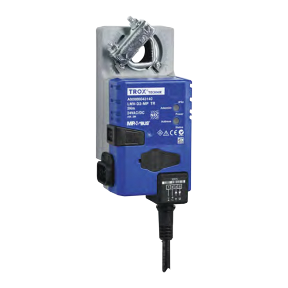
Technical data Technical data General operating conditions of the control components Ambient temperature 10-50 °C Ambient humidity 5-90% rh VAV terminal units Type Part number LMV-D3L-MP-F A00000043143 LMV-D3-MP-F A00000043141 TVJ, TVT NMV-D3-MP A00000043142 TZ-Silenzio, TA-Silenzio, TVZ, TVA LMV-D3-MP A00000043140 2 × LMV-D3-MP A00000043140 Compact controller LMV-D3L-MP-F 24 VAC ±... - Page 33 Technical data Compact controllers LMV-D3-MP and LMV-D3-MP-F 24 VAC ± 20%, 50/60 Hz Supply voltage 24 VDC -10/+20% Supply voltage 4 VA max. Power rating Max. 2 W Power rating Torque 5 Nm Run time for 90° 110 – 150 s Setpoint value signal input 0 –...
-
Page 34: Declaration Of Conformity
Declaration of conformity Declaration of conformity We hereby declare that the Compactregler complies with all relevant provisions of the following EC guide- lines: Guideline 2014/30/EU Guideline 2014/35/EU Guideline 2011/65/EU The individual CE certificates can be found at www.trox.de . -
Page 35: Index
Index Index Systematic............29 System pressure too low........28 Adjustment Unsuitable installation situation......28 Constant volume flow control....... 25 Use outside the control area........ 28 Entire control range ..........25 Wiring fault............28 Variable volume flow control........ Functional test............26 Adjustment device ZTH Voltmeter.............. - Page 36 Index PC-Tool..............Transport..............9 Smartphone............24 Transport damage............9 Signs................6 Troubleshooting..........28 , 39 Smartphone............... 24 Staff................7 Use................6 Switch direction of rotation........27 Switching the direction of rotation......27 Volume flow rate range..........Symbols..............Systematic troubleshooting........39 Wiring................
-
Page 37: Appendix
Appendix Appendix Control component BC0-Compact for VAV terminal units... -
Page 38: Azth Menu Structure
ZTH menu structure ZTH menu structure ↑ ↓ LMV-D3-MP ↑ ↓ Volumen 0 m³/h Sollwert 150 m³/h ↑ ↓ Volumen 0 m³/h Dp: 0 Pa ↑ ↓ Volumen 0 m³/h Position 100 % ↑ ↓ Volumen 0 m³/h Volumen 0 m³/h →... -
Page 39: B Systematic Troubleshooting
Systematic troubleshooting Systematic troubleshooting Start troubleshooting Troubleshooting VAV terminal units with Compact controller Status 09.01.2020 VAV terminal unit with Compact-controller Supply voltage within the tolerance specifications? Check wiring, transformer Initiate function test (press Adaption push button) Positions Closed, Open, Control position are automatically moved successively (takes a few minutes;... - Page 40 position? position after Open Check system pressure approx. 180 s ? Minimum differential pressure maintained? Duct section shut off/fire damper closed? Closed or no change Systematic troubleshooting Adjustment Check/correct setting Vmin/Vmax Vmin/Vmax potentiometer Take note of setting 0 … V approved? usable control range of the VAV terminal units type Check setpoint value signal...
- Page 41 Germany TROX GmbH +49 (0) 2845 202-0 Heinrich-Trox-Platz +49 (0) 2845 202-265 47504 Neukirchen-Vluyn, Ger- E-mail: trox@trox.de many www.trox.de © TROX GmbH 2019...
Need help?
Do you have a question about the LVC and is the answer not in the manual?
Questions and answers