
Subscribe to Our Youtube Channel
Related Manuals for Sit 650 DELTA


Summary of Contents for Sit 650 DELTA
- Page 1 650 DELTA USE AND INSTALLATION INSTRUCTIONS Read the instructions before use. This control must be installed in accordance with the rules in force.
- Page 2 650 DELTA is a combination gas control with thermoelectric flame supervision device and ON/OFF thermostatic control. 650 DELTA is designed and intended for gas fired storage water heaters. TECHNICAL DATA Inlet gas connection 1/2” NPT Main burner outlet 0.7500 - 18 - UNS 2B inverted flare Pilot outlet 7/16”- 24 - UNS 2B...
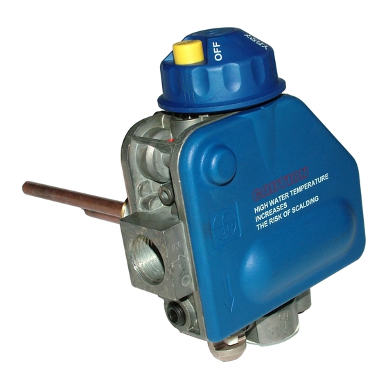
- Page 3 VALVE DESCRIPTION Ignition button for thermoelectric flame supervision device Control knob Reference arrow mark Gas inlet with protective dust cap Main gas outlet with protective dust Pilot outlet Outlet pressure test point Thermocouple connection 10 Mounting flange 11 Thermostat Rod 12 ECO Well 13 Piezoelectric igniter (Optional) 14 Plastic cover (Optional)
- Page 4 INSTALLATION When installation of this product begins… 1. Read all of these instructions carefully. Failure to follow these instructions could damage the product or cause dangerous conditions. 2. Check the ratings given in the instructions and on the appliance to make certain that the control is suitable for your application.
- Page 5 INSTALLING THE VALVE 1. Install the valve using the provided mounting flange. Screw using using the specific tool SIT code 0.999.996, suitable as accessory. Tighten to 45 ÷ 60 ft·bs torque. 2. Mount the valve so the flow of gas is consistent with the gas flow arrows on the valve.
- Page 6 AVOID ANY DAMAGE TO THE DEVICE (kNOCkS,FALLS,ETC.). IN CASE OF FALL OF THE VALVE, IT IS RECOMMENDED NOT TO USE IT. WARNING! THE 650 DELTA VALVE IS DISPOSABLE. THE VALVE ALREADY MOUNTED ON A STORAGE WATER HEATER MUST NOT BE REMOVED FROM THE STORAGE WATER FOR REUSE ON ANOTHER WATER HEATER. WARNING! Do not tamper with sealed parts.
- Page 7 pilot flame remains lit. If it goes out, repeat the ignition process, starting from the OFF position. Fig. 4: PILOT position Fig. 5: Ignition button PILOT and Piezo Igniter button Main burner ignition Turn the control knob counter-clockwise to the ON position (Fig.6).
- Page 8 SETTINGS AND ADJUSTMENTS The valve is preset at the factory, and is not field adjustable. Verify the outlet pressure via the 1/8”NPT outlet pressure test plug (8 in Fig. 11). Upon completion of testing, the sealing plug must be reinstalled using a 3/16” hex key, with 22 lbf·in of torque and a gas leak test must be performed.
- Page 9 SHUTDOWN PERFORMANCE TEST WARNING! Fire or Explosion Hazard. Can cause severe injury or death. Perform the safety shutdown check any time work is done on a gas system. 1. Place the appliance in operation. The pilot and main burners should be lit. 2.
- Page 10 Fig.12 & 13. Discard the old igniter. 5. Position the new igniter, available as spare part SIT code 0073002, into his seat of the gas valve, as shown in Fig.14. Apply by hand a maximum force of 44 lbf (20 Kgf ) on the button of the igniter.
Need help?
Do you have a question about the 650 DELTA and is the answer not in the manual?
Questions and answers