
Related Manuals for Sit 820 NOVA


Summary of Contents for Sit 820 NOVA
- Page 1 8 2 0 N O V A Read the instructions before use. This control must be installed in accordance with the rules in force.
- Page 2 English...
-
Page 3: Specifications
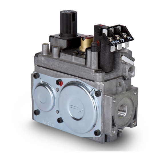
APPLICATION The 820 Nova Millivolt combination gas control is an On/Off gas valve suitable for use with gas fireplaces, gas log sets, gas space heaters and other gas heating equipment. Millivolt control permits complete regulation of the appliance, without requiring main supply voltage. -
Page 4: Working Diagram
WORKING DIAGRAM Versions with On/Off adjustment INLET MAIN BURNER PILOT BURNER Versions with manual flow adjustment INLET MAIN BURNER PILOT BURNER VALVE DESCRIPTION 15 6 1. ON/PILOT/OFF Knob 9. Pilot outlet 2. Manual HI-LO adjustment or pressure regulator 10. Main gas outlet adjustment 11. -
Page 5: Electrical Data
ELECTRICAL DATA MAIN OPERATOR SPECIFICATIONS Minimum open circuit voltage ≥ 325mV Minimum closed circuit voltage ≥ 100mV Operator resistance 2.25Ω ± 0.5Ω SAFETY MAGNET SPECIFICATIONS Coil resistance 0.015Ω ~ 0.021Ω TYPICAL HOLD IN AND DROP OUT SPECIFICATIONS Hold In Drop Out True Millivolt <10mA >4mA... - Page 6 WARNING: Fire or Explosion Hazard. Can cause property damage, severe injury or death. Follow these instructions completely. 1. Turn off gas supply at the appliance service valve before installation, and perform a Gas Leak Test after the installation is completed. 2.
-
Page 7: Installing The Valve
INSTALLING THE VALVE 1. Mount the valve in the desired position. 2. Mount the valve so the flow of gas is consistent with the gas flow arrows on the valve. 3. Apply a moderate amount of quality pipe compound (DO NOT USE TEFLON TAPE) to the pipe only, leaving two end threads bare. -
Page 8: Operation
MILLIVOLT “PLUS” VERSION WIRING DIAGRAM Pilot burner Room thermostat MILLIVOLT VERSION WIRING DIAGRAM Pilot burner Room thermostat 10 12 WARNING: Never connect valve to line voltage. Failure to follow this will result in damage to equipment and could result in severe injury or death. -
Page 9: Final Checks
Igniting the main burner Stand-by position Turning off Confirm that the thermostat is To maintain a flame at the pilot Turn the control knob to the closed. Turn the “HI/LO” knob burner with the main burner “OFF” position. to the “LO” setting. Turn the off, turn the control knob to the control knob to the “ON”... - Page 10 - If a leak is detected, tighten the pipe connections and repeat leak test. - Light the main burner. - With the main burner in operation, paint all piping connections from the valve with a soap and water solution. - If another leak is detected, tighten the connection. - If after tightening the connections the leak is still present, replace the leaky part or valve.
- Page 11 according to manufactures instructions. - Use leak test explained in these instructions to test for leaks. - Relight the main burner in both the “HI” and “LO” positions to verify proper burner ignition and operation. Fig. B...
- Page 12 VALVE CONVERSION (CONVERTIBLE HI-LOW VERSION) - Turn control knob to the “OFF” position, and shut off the gas supply to the valve. - Allow the valve to cool down to room temperature. - Remove the black protection cap by hands (fig. 1) . - Insert a 5/32”...
-
Page 13: Maintenance
Maintenance This valve is not field serviceable. There are no replaceable parts. Do not disassemble, or attempt replacement of any parts on or in the valve. Improper adjustment or tampering with settings can result in severe injury or death. If the main burner does not ignite when called for… 1. - Page 16 SIT Group...
Need help?
Do you have a question about the 820 NOVA and is the answer not in the manual?
Questions and answers