
Subscribe to Our Youtube Channel
Related Manuals for Sit 849 Sigma MOD-S


Summary of Contents for Sit 849 Sigma MOD-S
- Page 1 ONLY FOR VERSIONS WITH VENT DIAMETER LARGHER THAN 0.56 mm SIT code: 0.xxx.xxx 849 Sigma MOD-S USE AND INSTALLATION INSTRUCTIONS Read the instructions before use. This control must be installed in accordance with the rules in force.
- Page 2 Fig. 1...
-
Page 3: Main Features
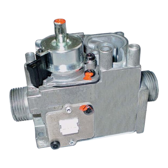
Multifunctional gas control with a pressure regulator, a current controlled modulating device and a gas flow sensor. The location for gas orifice (restrictor) is on the outlet of the multifunctional control. The control is designed for use in domestic gas appliances using 2 nd and 3 rd gas families. The designed lifetime* of this product is 500 000 cycles or 10 years (based on date code) according to the standard EN 126 and the table on designed lifetime as stated in the Afecor document, see http://www.afecor.org/news.html. -
Page 4: Technical Data
TECHNICAL DATA The technical data specified below refers to the European standards EN 126 “Multifunctional controls for gas-burning appliances”. 2 nd , 3 rd Gas families Maximum inlet pressure 60 mbar Ambient temperature range 0 to 60 °C Storage temperature range -30 to 70 °C Torsion and bending resistance Group 2... - Page 5 Modulating characteristic with vertical modulator axis (α=0) Modulator current [m A] Gas Flow Sensor Supply voltage 3.3 Vdc Output C protocol Gas Flow Sensor diagram Output sensor [reading as decimal fixed point]. 18000 G271 15000 12000 9000 6000 3000 MASS FLOW [Nl/h]...
-
Page 6: Installation
INSTALLATION 849 Sigma MOD-S conforms to current safety standards. Installation on appliances must nevertheless be checked with respect to the specific installation requirements for the appliance. All the installation and adjustment operations must be carried out exclusively by qualified personnel and on the basis of the specific characteristics of the user appliance and following the instructions given in this booklet. - Page 7 WARNING DO NOT SUbjECT THE VALVE TO bENDING IN ExCESS OF 35 NM AND TORQUE IN ExCESS OF 25 NM WARNING IN CASE OF OVERPRESSURE OF THE INPUT GAS ON THE VALVE GREATER THAN 1 bAR, REPLACE THE VALVE. WARNING DO NOT OPEN, INTERFERE WITH OR MODIFy THE VALVE.
- Page 8 Inlet and outlet gas connections with gasket Use gas pipes with a suitable flat annular surface to allow the use of a sealing gasket, see Fig 2. In particular for outlet connection, make sure that the gasket does not interfere with the fitted restrictor and make sure that the surface of the gasket does not obstruct the space beetwen the restrictor and the outlet pipe, see enlarged view in Fig.2.
-
Page 9: Electrical Connections
Electrical connections All electrical connections must be made in accordance with current electrical standards. Check that the voltages given to the modulator and to the sensor are correct. Disconnect the power supply before starting installation. Check that all connections are made properly The modulator is supplied with a male contact Molex compatible, suitable for female Molex series 70066 connector. -
Page 10: Settings And Adjustments
SETTINGS AND ADjUSTMENTS There are not any adjustments in this multifunctional control. Check inlet and intermediate pressure using the pressure test points provided. To open the pressure test points use a 4.9 mm screwdriver for slot-head screws. After setting, carefully seal test points ensuring gas soundness. Recommended torque: 1.0 Nm.
Need help?
Do you have a question about the 849 Sigma MOD-S and is the answer not in the manual?
Questions and answers