Advertisement
Table of Contents
The Tools You Trust
555 Kimberly Drive, Carol Stream IL 60188
Phones Worldwide: +1 847/455-8677
Toll Free US Only: 800/877-1347
Fax: 847/455-0347
CustomerService@srtorque.com
www.srtorque.com
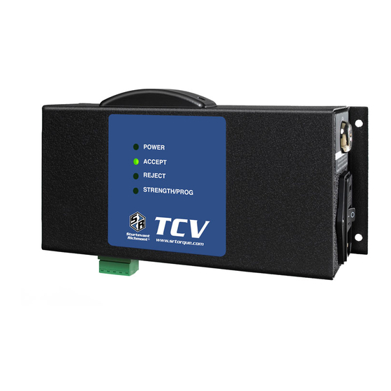
Torque Control Verifier [TCV]
Quick Start Card
This Quick Start Card is designed as a ready reference for the TCV owner. The TCV Owners Manual provides
complete information on the TCV and the associated software. The TCV Manual is provided in Adobe® Portable
Document Format® [PDF] on the enclosed TCV Manual CD-ROM. The PDF file is also available in the Technical
Information > Instructions section of our website, www.srtorque.com.
Power
120 VAC or 240 VAC, selectable via the Power Entry Module [PEM] on the right side. The current setting is displayed in the cutout
window to the front of the power cord receptacle. To change the setting, (1) remove the power cable from the PEM, (2) insert the tip
of a flat tip screwdriver into the slot just inside the front of the PEM and (3) twist slightly to unlock the Voltage Selector/Fuse Holder
from the PEM. (4) Slide the Voltage Selector/Fuse Holder out of the PEM. The Voltage Selector is a removable/reversible card on
rails in the holder. To change the voltage setting, slide the Voltage Selector Card out, invert it and reinsert it by sliding it back into
the rails that hold it in place. Finish by reinserting the Voltage Selector/Fuse Holder back into the PEM.
The fuse is replaced by removing the Voltage Selector/Fuse Holder from the PEM as described in the paragraph above. The
cylindrical fuse is removed by gently pulling it from the holder. Insert replacement into the same location, then reinsert Voltage
Selector/Fuse Holder into the PEM.
PLC Connector and I/O
The TCV is supplied with a 5-pin PLC Connector (Phoenix style) on the bottom of the case beside the RJ-11 jack receptacle. The
PLC Connector has both an internal and external component. The external component is L-shaped, and has a push-pull installation
and removal. Remove the external component by simply pulling it straight out (down) from the unit. The connection pins on the
PLC Connector are numbered from 1 to 5, with Pin 1 beside the RJ-11 receptacle. The pin numbers and purpose for each are as
given in the table below.
Pin 1
Pin 2
Pin 3
Pin 4
Pin 5
Reject Relay
Accept Relay
Relay Common
Reset Common
Reset Input
The external component of the PLC Connector uses screw terminals to secure the wires to the PLC or other devices. To wire each
pin, remove ¼" (3 mm) of insulation from the wire(s), loosen the screw in the terminal to open the jaws of the terminal, insert the
wire, and tighten the screw. The TCV has a maximum capacity of 250 VAC at 8 amps. The TCV is set to work with PLC voltages
up to 48 VDC. For use with voltages over 48 VDC, see Chapter 2 in the TCV Manual.
The relays are set to momentary (200 ms) as the factory default. To change the setting to latching, use the supplied software. To
use the relays, a voltage needs to be placed on Pin 3. The voltage is returned on the Reject Relay if the FM Switch Wrench has a
rejected cycle, and on the Accept Relay if the wrench has an accepted cycle.
Programming
The TCV is programmed via the Clk-tune software on the CD, and communicated to the TCV through the computers serial port, the
RS-232 to RJ-11 converter, and the RJ-11 cable that come with the unit.
To connect the TCV to the computer, insert the RS-232 to RJ-11 converter into the serial port to be used with the TCV. Connect
one end of the RJ-11 cable to the converter, and the other end to the RJ-11 receptacle on the bottom of the TCV.
To install the software, insert the CD into the CD drive of the computer. Use "My Computer" or Windows Explorer to display the file
list on the CD. Double-click the file "Setup.exe". The installation screen will be displayed. Follow the on-screen prompts to install
and configure the software. Close all windows when the installation is complete.
To run the software, either double-click the Clk-tune icon on the desktop (if chosen at installation) or click on Start > Programs >
Clk-tune. The main window of the program will be displayed. The upper-left portion of the window has a list of the six elements
used by the TCV, with a value window to the right of each. The value window is used to set the value for each element. The lower-
left quadrant provides a graphic depiction of the settings for the timers: Min Pull, Max Pull, and Time Between Cycles. The upper-
right section allows selection of the Comm Port (serial port) to which the TCV is connected. The lower-right section has six buttons
for rapid access to six functions: Upload (up arrow) settings from TCV, Stop (communication with TCV), Download (settings to
TCV), File (retrieve saved settings), Save (settings to disk), and Exit (program).
Advertisement
Table of Contents

Subscribe to Our Youtube Channel
Related Manuals for Sturtevant Richmont TCV


Summary of Contents for Sturtevant Richmont TCV
- Page 1 Clk-tune. The main window of the program will be displayed. The upper-left portion of the window has a list of the six elements used by the TCV, with a value window to the right of each. The value window is used to set the value for each element. The lower- left quadrant provides a graphic depiction of the settings for the timers: Min Pull, Max Pull, and Time Between Cycles.
- Page 2 To choose whether the TCV beeps or not on receipt of an acceptable pull from the FM Switch Wrench, click on the pull-down menu in the settings column for it, and choose YES or NO. The TCV will automatically beep twice on a rejected wrench cycle, but may be set to beep once or not at all when an acceptable cycle occurs.
Need help?
Do you have a question about the TCV and is the answer not in the manual?
Questions and answers